1
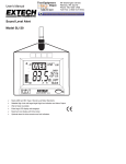
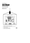
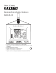
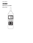
User's Manual
Sound Level Monitor
Model SL120
Meets ANSI and IEC Type 2 Sound Level Meter Standards
Settable High Limit with large OVER indication and Alarm Output
Wall or Desk mountable
Extra large LCD display with bargraph
Maximum level display with time stamp
Optional alarm kit drives remote over limit indicators.
Introduction
Congratulations on your purchase of the Extech SL120 Sound Level Monitor. Designed for
wall mount, desk, tripod mount or hand held operation, this meter meets ANSI and IEC
Type 2 Sound Level Meter standards. Included is a High Limit Set Point with a large OVER
indication when the set level is exceeded. An Alarm Output can be used in conjunction with
the optional Alarm Module Kit to power a larger or a remote indicating device such as a
“QUIET” sign. Professional features include programmable A/C Weighting and Fast/Slow
Response time, Max Memory with time stamp, and a Clock display. The microphone can
be rotated 180 degrees to accommodate any meter location or it can be placed at a remote
location using the optional Remote Microphone Cable. A programmable ON/OFF time
extends battery life to 30 days when programmed 8 hours per day. Careful use of this
meter will provide years of reliable service.
Specifications
Applicable standards
Display
Frequency bandwidth
Microphone
Measurement ranges
Frequency weighting
Response time
Resolution
Max Hold
Alarm output
Limit range
Under range indication
Over range indication
Power
Battery life
Operating temperature
Operating humidity
Dimensions / Weight
Meets IEC 60651-1979 and ANSI S1.4 1983 Type 2
SLM standards
4.6” x 3.125” multifunction LCD
31.5 Hz to 8 KHz
0.5” Electret Condensor Microphone (remoteable)
30 to 80dB, 60 to 110dB, 80 to 130dB
‘A’ and ‘C’ (Programmable)
Fast (125ms) / Slow (1s) (Programmable)
0.1dB
Maximum reading is displayed with time
3.5mm Mono Phone Plug, Maximum: 3.4mA @ 5 Vdc,
Minimum Output Voltage: 2.5 Vdc
30 to 130dB
“- - -“
“OL”
8 AA Batteries; optional AC adaptor (9V@350ma)
240hrs continuous (approx); 30 days @ 8hrs/day
o
o
32 to 122 F (0 to 50 C)
Less than 80% RH
8.75x7.1x1.25" / 0.63 lbs. (22x18x3.2mm / 285g)
2
Version 1.2 9/05
Meter Description
1.
Microphone
2.
Over Limit Display
3.
Bargraph
4.
dB display
5.
OFF/ON/AUTO switch
2
6.
Clock display
3
7.
Max level display with time stamp
4
8.
Set limit
5
9.
MAX RESET button
1
6
7
8
9
Rear Panel
1.
Range select switch
2.
Time set buttons
3.
Limit set buttons
4.
Calibration adjustment
5.
A/C select button
6.
F/S select button
1
30-80
2
4 5 6
3
80-130
LIMIT
60-110
3
Version 1.2 9/05
Sound Level Monitor Operation
Initial Configuration
1. Install 8 AA batteries
2. Setting the TIME
a)
Press and Hold the Time SET button until the hours display
begins to flash.
b)
Press the Time up arrow button until the hour is set.
c)
Press the SET button. The minutes display will flash. Adjust as needed.
d)
Press the SET button to step through and the arrow button to adjust;
Time of day
Hour
Time of day
Minutes
Time of day
AM / PM / 24 Hour
Year
Month
Day
Auto ON
Hour
Auto ON
Minutes
Auto OFF
Hour
Auto OFF
Minute
A/C Frequency Weighting
Change the Frequency Weighting by pressing the
appear on the display.
'A/C' button. The 'A' or 'C' icon will
With ‘A’ weighting selected, the frequency response of the meter is similar to the response
of the human ear. ‘A’ weighting is commonly used for environmental or hearing
conservation programs such as OSHA regulatory testing and noise ordinance law
enforcement. ‘C’ weighting is a much flatter response and is suitable for the sound level
analysis of machines, engines, etc.
Most noise measurements are performed using 'A' Weighting and SLOW Response.
Slow/ Fast Response
Press the
button to select Fast or Slow response as desired. F or S will appear in the
bottom of the LCD display.
Select FAST to capture noise peaks and noises that occur very quickly. Select the SLOW
response to monitor a sound source that has a consistent noise level or to average quickly
changing levels.
Select Slow response for most applications.
Range Selection
Slide the Range switch to the 30-80, 60-110 or the 80-130 position.
The selected range will be indicated on the LCD bargraph. If the
measured dB level exceeds the range selected “OL” will be
displayed. If the measured dB level is below the selected range “- - -“ will be
displayed.
Normally, select the range in which the upper dB level is greater than any
expected sound pressure level. The 60 to 110dB range is the most commonly
used range. Use the 30 to 80dB range in quieter areas such as offices and classrooms.
Note: When the range is changed the Max display may indicate an overload “OL”. Press
the MAX RESET button to clear the MAX display.
4
Version 1.2 9/05
Over Limit Set
Press the up or down LIMIT arrow buttons to set the OVER limit
level as displayed on the LCD. If the measured dB level exceeds
the set limit, the
indication will appear in the display and the
over limit signal will appear at the alarm output connector. The
display indication and output signal will remain active as long as the
sound pressure level exceeds the set limit.
MAX Hold
The MAX display indicates and holds the highest dB level measured
since the meter was turned on or since the Max Reset button was
pressed. The time and date of the max reading is also displayed.
To clear the display and start a new measurement session, press the
front panel MAX RESET button. If the measured level exceeds the maximum for the range
selected the MAX display will indicate “OL” (overload).
Programmable OFF/ON/AUTO time
The meter is powered by 8 AA batteries or via an AC adaptor for permanent installations.
Continuous battery life is approximately 240 hours (10 days). By programming the ON/OFF
time, the battery life can be greatly extended (30 days assuming an 8 hour day). The ON
and OFF times are programmed as described in the initial configuration
paragraph. The meter will operate continuously with the power switch in
the ON position. The ON/OFF time will be controlled by the meter when
the power switch is set to the AUTO position.
Calibration
The sound level meter should be calibrated on a regular basis to assure that the meter’s
performance and microphone sensitivity has not change. Some operational directives
require daily calibration checks (OSHA). Extech offers several acoustic calibrators to
perform the calibration.
1. Set the meter to the 60 to 110dB or 80 to 130dB range.
2. Place the external calibrator over the Sound Level
Monitor's microphone and turn the Calibrator on.
3. The meter should read close to the calibrator's dB output
level. Typical Calibrator output levels are 94dB and 114dB.
4. If the meter is within ± 0.2 dB of the calibrator’s output, no
adjustment is necessary.
5. Adjust the calibration pot on the rear of the meter to the
proper level.
5
Version 1.2 9/05
Meter Placement
The meter can be used Handheld, Wall mounted, Desk mounted or Tripod mounted. For
wall mount operation, orient the microphone perpendicular to the wall to minimize the
affect of acoustic reflections. For desk mounting, extend the rear legs and lock in place
with the hinged locks. The tripod mounting nut is located on the bottom of the unit.
Remote Microphone (optional)
The optional 15’ remote microphone cable can be used to place the microphone in one
location while viewing the dB levels and/or generating a high limit alarm at another
location. To remove the microphone, unscrew the holding collar and lift the microphone off
the connector. The extension cable can then be plugged into the matching connectors.
Calibration should be performed after the cable is installed.
Alarm Output (optional)
The alarm output drives the optional Remote Alarm Relay Module (cable and relay) when
the LIMIT set point is exceeded. The relay module can be used to power external warning
signs, “QUIET” signs or other indicating devices when the sound level is higher than the
programmed limit. Refer to the manual supplied with the module for connection
information.
Relay Module
HEARING
PROTECTION
REQUIRED
Indicating Device
AC or DC Power
Note: For up-to date information on this product, optional accessories and literature, call
or go to www.extech.com.
6
Version 1.2 9/05
Measurement Considerations
1. Use a windscreen (not included) to cover the microphone in windy conditions.
2. Calibrate the meter often, especially if the meter has been idle for a long period of time.
3. Do not store/operate the meter in areas of high temperature or humidity.
4. Keep the meter and the microphone dry.
5. Avoid severe vibration when using the meter.
6. Remove the battery when the meter will be stored for long periods of time.
Frequency Weighting curves
Weighting Response Curves
0
C
-10
A
-20
-30
-40
-50
20
50
100 200
500
1k
2k
5k
10k 20k
Frequency (Hz)
OSHA permissible levels
Permissible Noise Exposure Limits
Duration per Day (hours)
Sound Level db(A) Slow response
16
85
8
90
6
92
4
95
3
97
2
100
1-1/2
102
1
105
1/2
110
¼ or less
115
7
Version 1.2 9/05
Battery Replacement
The 8 AA batteries are located in the rear battery compartment. When the battery icon
appears on the meter's LCD, it is time to replace the battery.
Calibration and Repair Services
Extech offers complete repair and calibration services for all of the products we sell.
For periodic calibration, NIST certification or repair of any Extech product, call customer
service for details on services available. Extech recommends that calibration be performed
on an annual basis to insure calibration integrity.
Support line (781) 890-7440
Technical support: Extension 200; E-mail: [email protected]
Repair & Returns: Extension 210; E-mail: [email protected]
Product specifications subject to change without notice
For the latest version of this User’s Guide, Software updates, and other
up-to-the-minute product information, visit our website: www.extech.com
Warranty
EXTECH INSTRUMENTS CORPORATION warrants this instrument to be free of defects in parts and
workmanship for one year from date of shipment (a six month limited warranty applies on sensors and
cables). If it should become necessary to return the instrument for service during or beyond the warranty
period, contact the Customer Service Department at (781) 890-7440 ext. 210 for authorization or visit our
website at www.extech.com (click on ‘Contact Extech’ and go to Service Department to request an RA
number). A Return Authorization (RA) number must be issued before any product is returned to Extech. The
sender is responsible for shipping charges, freight, insurance and proper packaging to prevent damage in
transit. This warranty does not apply to defects resulting from action of the user such as misuse, improper
wiring, operation outside of specification, improper maintenance or repair, or unauthorized modification.
Extech specifically disclaims any implied warranties or merchantability or fitness for a specific purpose and
will not be liable for any direct, indirect, incidental or consequential damages. Extech's total liability is limited
to repair or replacement of the product. The warranty set forth above is inclusive and no other warranty,
whether written or oral, is expressed or implied.
Copyright © 2004 Extech Instruments Corporation.
All rights reserved including the right of reproduction in whole or in part in any form.
8
Version 1.2 9/05