1
USB I/O Card model A and B
User Manual
October 2013
USB I/O Card
Table of Contents
1
Features
4
2
Technical Specifications
4
3
Interfacing
Board Overview
INPUTS Connector
OUTPUTS Connector
PWM1-8 Connector
PWM9-16 Connector
Temperature Sensor
LED Driver
Model A
Model B
5
5
6
6
7
7
8
8
8
8
4
Software
Overview
Linux
Program axiiocardgui
User Interface
Command Line
Distribution Package
Installation
Software Revision
Software License
Package libaxiiocard
Notes
Software Revision
Package libaxiiocard-java
Software Revision
9
9
9
10
10
14
14
15
15
15
16
16
16
16
16
5
USB Interface
Serial Paths
Linux
Windows
17
17
17
18
6
Application Notes
19
7
Disclaimer
20
8
Contact Information
20
2
User Manual
USB I/O Card
Revision History
Date
Authors
Description
2012-08-20 Peter S'heeren
Initial release.
2012-11-25 Peter S'heeren
Added model B.
Second release.
2013-03-11 Peter S'heeren
Added sections about software and serial interface.
Third release.
2013-10-27 Peter S'heeren
Updated for latest axiiocardgui program (issued
2013-10-27).
Added sections for libaxiiocard and libaxiiocardjava (issued 2013-10-27).
Fourth release.
User Manual
3
USB I/O Card
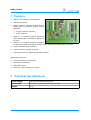
1 Features
▪
USB 2.0 Full-Speed serial interface.
▪
USB bus-powered.
▪
Model A and B - LED driver provides 16
pulse-width modulation (PWM) output
channels:
▪
8 open-collector outputs.
▪
8 TTL outputs.
▪
Model A - 16 output channels providing
8-bit pulse-width modulation (PWM) at
97 kHz.
▪
Model B - 16 output channels providing
12-bit pulse-width modulation (PWM) output channels at about 40 to 1000 Hz.
▪
8 opto-isolated input channels.
▪
8 open-collector output channels.
▪
Ultra high accuracy digital temperature sensor.
Applications include:
▪
Home automation (domotics).
▪
Industrial automation.
▪
RGB LED control.
▪
Model B - Motor and servo control.
2 Technical Specifications
Power supply
USB bus-powered 500 mA max.
Dimensions
105 mm x 76 mm x 15 mm (W x D x H)
Weight
51 g
4
User Manual
USB I/O Card
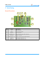
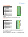
3 Interfacing
Board Overview
4 2 1
3
5
8
7
Mark
Label
1
K5
2
LED17
Power LED indicator
3
INPUTS
Input channels
4
INPUTS[1..8]
5
OUTPUTS
6
OUTPUTS[1..8]
7
PWM1-8
8
PWM9-16
User Manual
6
Description
USB connector
Input channels state LED indicators
Output channels
Output channels state LED indicators
PWM output channels 1..8
PWM output channels 9..16
5
USB I/O Card
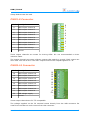
INPUTS Connector
Mark
Description
8
Input channel 8
7
Input channel 7
6
Input channel 6
5
Input channel 5
4
Input channel 4
3
Input channel 3
2
Input channel 2
1
Input channel 1
-
Ground
-
Ground
8
7
6
5
4
3
2
1
-
The input voltage range on the input channels is 5 – 30 V. Such input voltage is seen as a
logical one.
The input channels are galvanically isolated from the rest of the circuit.
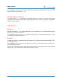
OUTPUTS Connector
Mark
Description
8
Output channel 8
7
Output channel 7
6
Output channel 6
5
Output channel 5
4
Output channel 4
3
Output channel 3
2
Output channel 2
1
Output channel 1
+
Positive load voltage
-
Ground
8
7
6
5
4
3
2
1
+
-
The output channels are open-collector outputs that switch to ground. Each output can
drive max. 500 mA at 50 V. The max. output current of all outputs together is 1 A.
For inductive loads it's recommended to connect the positive supply voltage of the load to
the positive load voltage terminal.
When driving inductive loads (for example, relays) it's also recommended to connect a
6
User Manual
USB I/O Card
clamp diode across the load.
PWM1-8 Connector
Mark
Description
8
PWM output channel 8
7
PWM output channel 7
6
PWM output channel 6
5
PWM output channel 5
4
PWM output channel 4
3
PWM output channel 3
2
PWM output channel 2
1
PWM output channel 1
+
Positive load voltage
-
Ground
8
7
6
5
4
3
2
1
+
-
These output channels are meant for driving LEDs. It's not recommended to drive
inductive loads.
The output channels are open-collector outputs that switch to ground. Each output can
drive max. 500 mA at 50 V. The max. output current of all outputs together is 1 A.
PWM9-16 Connector
Mark
Description
16
PWM output channel 16
15
PWM output channel 15
14
PWM output channel 14
13
PWM output channel 13
12
PWM output channel 12
11
PWM output channel 11
10
PWM output channel 10
9
5V
-
PWM output channel 9
USB voltage supply
Ground
16
15
14
13
12
11
10
9
5V
-
These output channels are 5V TTL compatible.
The voltage supplied on the 5V terminal comes directly from the USB connector. Be
careful not to draw too much current from this connector.
User Manual
7
USB I/O Card
In combination with a resistor and a capacitor, an output channel can be set up as an
analog output in the range 0 – 5 V.
Temperature Sensor
The NXP SE95 is a temperature-to-digital converter using an on-chip band gap
temperature sensor and sigma-delta analog-to-digital conversion. The SE95 is compatible
with the LM75/LM75A.
LED Driver
Model A
The NXP PCA9635 is an 8-bit PWM LED driver optimized for red/green/blue/amber
(RGBA) color mixing applications.
The PCA9635 uses a frequency of 97 kHz for PWM control. An additional frequency of 190
Hz provides the dimming feature.
Model B
The NXP PCA9685 is a PWM LED driver optimized for red/green/blue/amber (RGBA) color
mixing applications.
The PCA9685 uses a frequency of about 40 to 1000 Hz for PWM control enabling it to
drive motors and servos.
The on and off times of the PWM output signal can be programmed for each channel
individually. This design aids in minimizing current surges.
8
User Manual
USB I/O Card
4 Software
Overview
The USB I/O Card comes with a number of software programs that run on a number of
computer systems and operating systems. Since the I/O card is USB-based, it can be
easily deployed on a great number of systems.
Linux
This document makes the following assumptions for Linux users:
▪
You've basic knowledge of Linux commands.
▪
You've a personal log in that's not root (unless you always log in as root).
▪
You know how to run programs as root (sudo command, setuid access right flag).
▪
You know how to log in as root (log in prompt, the su command).
This document describes commands entered at the command prompt. When entering a
command at the prompt of your personal log in, the document uses the $ notation. For
example:
$ sudo lsof -p 1234
A command entered at the prompt of the root log in is written with the # notation. For
example:
# ls -al
User Manual
9
USB I/O Card
Program axiiocardgui
The axiiocardgui program is a
graphical
front-end
application
that visualizes the state of the
USB I/O Card and allows the user
to interact with the USB I/O Card.
The program runs on a variety of
systems including Linux for x86
and ARM, and Windows 2000 and
later.
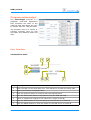
User Interface
The Interface Panel
1
2
3
4
6 5
7
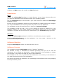
Mark Description
10
1
Enter the path to the serial port here. The USB driver creates the serial path.
2
Status information is displayed here.
3
Click the Connect button to connect with the USB I/O Card.
4
Click the Disconnect button to disconnect from the USB I/O Card.
5
Check to enable the outputs of the LED driver (model A and B).
6
Click the PWM button to show the panel for the LED driver of model A.
7
Click the PWM2 button to show the panel for the LED driver of model B.
User Manual
USB I/O Card
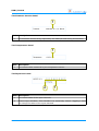
The Firmware Version Panel
1
Mark Description
1
The firmware version string reported by the USB I/O Card during enumeration.
The Temperature Panel
1
Mark Description
1
The current value measured by the temperature sensor.
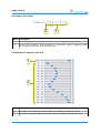
The Input Port Panel
2
1
Mark Description
1
The current state of the input channels.
2
Inverse logic checkbox. This checkbox is a visual-only control. Toggling it does
not change the state of the input channels.
User Manual
11
USB I/O Card
The Output Port Panel
2
1
Mark Description
1
The current state of the output channels. Click to toggle the output state.
2
Inverse logic checkbox. This checkbox is a visual-only control. Toggling it does
not change the state of the output channels.
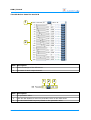
The LED Driver Panel for model A
1
2
Mark Description
12
1
The state of the PWMGRP register. Slide the scrollbar to adjust the value.
2
The state of registers PWM0 to PWM15. Slide a scrollbar to adjust the value.
User Manual
USB I/O Card
The LED Driver Panel for model B
1
2
Mark Description
1
General settings of the LED driver.
2
The state of each output channel.
1 2 3
Mark Description
1
The prescaler value.
2
Click the Set button to write the prescaler value to the LED driver.
3
The calculated PWM frequency based on the prescaler value.
User Manual
13
USB I/O Card
1
2 3 4 5 6
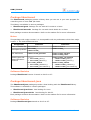
Mark Description
1
Expected PWM wave form of the output signal. You can click and drag the top
triangle and bottom triangle to change the values of ON time and OFF time.
2
The value of the ON time. Click the Set button to apply.
3
The value of the OFF time. Click the Set button to apply.
4
The state of the Always ON flag. Click the Set button to apply.
5
The state of the Always OFF flag. Click the Set button to apply.
6
Click the Set button to write the data specified in 2, 3, 4 and 5 to the LED driver.
Command Line
Not applicable. The program ignores the command line.
Distribution Package
The axiiocardgui package is supplied for various operating systems. The naming of the
packages is:
axiiocardgui-<arch>.<ext>
Where:
▪
<arch>: Architecture of the target operating system.
▪
<ext>: Extension denoting the format of the package file.
In Linux, you can query the architecture as follows:
$ gcc -dumpmachine
This command will give you a so-called multiarch tuple, like arm-linux-gnueabi. The
packages use a short name for the architecture as shown in the following table.
These are the currently available packages, tested with the indicated operating systems.
Note that this list is not exhaustive. Check the website for the most up-to-date packages.
Package
axiiocardgui-linux-armel.tar.gz
axiiocardgui-linux-armhf.tar.gz
axiiocardgui-linux-i486.tar.gz
axiiocardgui-linux-amd64.tar.gz
axiiocardgui-win32.zip
Multiarch Tuple
arm-linux-gnueabi
Tested operating systems
Linux 3.1.9 ARMv6, 32-bit, soft float
arm-linux-gnueabihf Linux 3.1.9 ARMv6, 32-bit, hard float
i486-linux-gnu
Linux 2.6.32 for x86 32-bit
x86_64-linux-gnu
Linux 2.6.32 for x86 64-bit
N.A.
Windows 2000/XP/Vista/7, 32-bit, 64-bit
Note that newer versions of an architecture usually support the provided version. For
14
User Manual
USB I/O Card
example, an i686 system will usually run i486 flawlessly.
Installation
Linux
Unpack the axiiocardgui package in a local directory in your home directory. Be sure
you pick the distribution that corresponds with your operating system.
Run the install.sh script in the context of your user account to install the axiiocardgui
program in Linux.
Be sure to run the installation script from the command line rather than the file manager.
The script will sudo and as such the system may ask for the root password.
The installation script will install the files in directory /opt/axiiocardgui.
The installation script will add a icon on your desktop by placing a desktop file in the
Desktop directory in your home directory. This feature works only if your window
manager is compliant with the Desktop Entry Specification by the freedesktop.org organization.
Windows
Unpack the axiiocardgui package for Win32 in a local directory on your system.
Execute axiiocardgui.exe to run the application. You may create a shortcut to the
executable file on your desktop.
Software Revision
Program axiiocardgui version 1.2 issued on 2013-10-27.
Software License
The computer program axiiocardgui is free of charge ("freeware").
It's allowed to copy or distribute the software providing that you do so with the
distribution in its entirety as described in chapter Distribution. It's forbidden to change
the software or any other files that are part of the distribution.
It's forbidden to sell, rent, or profit from the distribution in its entirety or the software or
any other files that are part of the distribution.
It's allowed to spread the distribution in a packaging format different from the packaging
format provided by Axiris.
User Manual
15
USB I/O Card
Package libaxiiocard
The libaxiiocard packages provide a library that you can use in your own program for
controlling one or more USB I/O Cards.
This library is available in various packages:
▪
libaxiiocard-gcc4: Package for use with GCC version 4 or later.
▪
libaxiiocard-msvc60: Package for use with Visual Studio 6.0 or later.
Each package contains documentation. Refer to the readme file for more information.
Notes
This package with major version 2 is incompatible with its predecessor which has major
version 1. The main differences are:
Component
Name of header file
Version 1
axiiocard.h
Version 2
libaxiiocard.h
Namespace prefixes AXIIOCARD_
LIBAXIIOCARD_
LIBAXIIOCARD_
User definitions
LIBAXIIOCARD_EXPORTS
LIBAXIIOCARD_EXPORTS
LIBAXIIOCARD_DYNLL
Handle types and
related allocation
functions
<none>:
▪ AXIIOCARD_Init()
▪ AXIIOCARD_Deinit()
AXIIOCARD_HANDLE
▪ AXIIOCARD_Connect()
▪ AXIIOCARD_Disconnect()
LIBAXIIOCARD_LIB_HANDLE
▪ LIBAXIIOCARD_Init()
▪ LIBAXIIOCARD_Deinit()
LIBAXIIOCARD_HANDLE
▪ LIBAXIIOCARD_Connect()
▪ LIBAXIIOCARD_Disconnect()
Software Revision
Package libaxiiocard version 2 issued on 2013-10-27.
Package libaxiiocard-java
The libaxiiocard-java packages provide a Java binding with the libaxiiocard library.
This software is available in various packages:
▪
libaxiiocard-java-linux: Java binding for Linux.
▪
libaxiiocard-java-win32: Java binding for Win32.
Each package contains documentation. Refer to the readme file for more information.
Software Revision
Package libaxiiocard-java issued on 2013-10-27.
16
User Manual
USB I/O Card
5 USB Interface
The USB I/O Card incorporates an FTDI USB to serial chip. This chip needs the Virtual
COM port (VCP) drivers supplied by FTDI. These drivers are available for most common
operating systems.
Serial Paths
You need to specify a serial path in order to communicate with a serial port. The next
sections explain in more detail how you specify serial paths in each supported operating
system.
Linux
Serial ports are accessible in the device directory structure. A serial path starts with
/dev. A serial path is case-sensitive.
The following table summarizes serial paths that are commonly found on Linux systems:
Serial Path
Serial Port
/dev/ttyS0
The computer's 1st on-board serial port
/dev/ttyS1
The computer's 2nd on-board serial port
/dev/ttyS2
The computer's 3rd on-board serial port
/dev/ttyS3
The computer's 4th on-board serial port
/dev/ttyUSB0
1st USB serial adapter
/dev/ttyUSB1
2nd USB serial adapter
/dev/serial/by-id/
This directory contains symbolic links to serial devices.
Each symbolic link name identifies a specific device.
/dev/serial/by-path/
This directory contains symbolic links to serial devices.
Each symbolic link name represents a hardware path to
the device, like a specific USB port on your computer.
Here are some useful commands you can run to get information about present serial
devices and their corresponding serial path. The following commands were run on a Linux
system with one on-board UART and one connected USB serial adapter.
Filter information from the kernel message buffer:
$ dmesg | grep 'tty'
[
0.000000] console [tty0] enabled
[
0.516785] serial8250: ttyS0 at I/O 0x3f8 (irq = 4) is a 16550A
[
0.517463] 00:0b: ttyS0 at I/O 0x3f8 (irq = 4) is a 16550A
[
0.559097] tty tty55: hash matches
[
66.076326] usb 2-1: FTDI USB Serial Device converter now attached to ttyUSB0
Use the setserial command to produce a list of serial paths:
User Manual
17
USB I/O Card
$ setserial -g /dev/ttyS* /dev/ttyUSB*
/dev/ttyS0, UART: 16550A, Port: 0x03f8, IRQ: 4
/dev/ttyS1, UART: unknown, Port: 0x02f8, IRQ: 3
/dev/ttyS2, UART: unknown, Port: 0x03e8, IRQ: 4
/dev/ttyS3, UART: unknown, Port: 0x02e8, IRQ: 3
/dev/ttyUSB0, UART: unknown, Port: 0x0000, IRQ: 0, Flags: low_latency
List serial devices in the device directory:
$ ls -l /dev/ttyS* /dev/ttyUSB*
crw-rw---- 1 root dialout
4, 64 2012-02-22 14:19 /dev/ttyS0
crw-rw---- 1 root dialout
4, 65 2012-02-22 14:19 /dev/ttyS1
crw-rw---- 1 root dialout
4, 66 2012-02-22 14:19 /dev/ttyS2
crw-rw---- 1 root dialout
4, 67 2012-02-22 14:19 /dev/ttyS3
crw-rw---- 1 root dialout 188,
0 2012-02-22 14:20 /dev/ttyUSB0
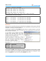
Windows
Serial ports are accessible through the Win32 device namespace, which is part of the NT
namespace. As such a serial path starts with \\.\ followed by the device name of the
serial port. A serial path is case-insensitive.
A serial port is typically named COM<x> where <x> is a number between 1 and 256.
Other naming schemes may apply and aliases may exist, depending on the serial driver
that controls the serial port.
You can obtain a list of available
in the device manager. Open
manager and view devices by
section named Ports (COM & LPT)
available serial and parallel ports.
serial ports
the device
type. The
contains all
The device name of a serial port is shown
between parentheses. In the picture to the
right, you can see two serial ports. COM1 is
the PC's on-board serial port, COM3
represents a USB serial adapter.
The serial paths to the serial ports in the
picture are:
Serial Path
Serial Port
\\.\COM1
Communications Port (COM1)
\\.\COM3
USB Serial Port (COM3)
Serial paths like COM1 (that's without the \\.\ prefix) will work because COM1 to COM9
are reserved names in the NT namespace. COM10 to COM256 aren't reserved names and
you'll have to specify the \\.\ prefix with these device names. By comparison, serial
path \\.\COM100 will work but serial path COM100 won't work.
18
User Manual
USB I/O Card
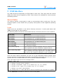
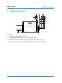
6 Application Notes
VCC: 12-24V
VCC
VCC
5-30V
VCC
R
G
B
USB I/O Board
0-5V
47K
TTL
PWM
1µF
GND
GND
GND
Overview:
▪
Output 8 is connected to a relay.
▪
PWM outputs 6 to 8 drive blue, green, and red LEDs.
▪
PWM output 9 is used for generating a voltage between 0 and 5 V.
▪
Input 1 reports logic level one when a voltage of 5 to 30 V is applied.
User Manual
19
USB I/O Card
7 Disclaimer
Axiris products are not designed, authorized or warranted to be suitable for use in space,
nautical, space, military, medical, life-critical or safety-critical devices or equipment.
Axiris products are not designed, authorized or warranted to be suitable for use in
applications where failure or malfunction of an Axiris product can result in personal
injury, death, property damage or environmental damage.
Axiris accepts no liability for inclusion or use of Axiris products in such applications and
such inclusion or use is at the customer's own risk. Should the customer use Axiris
products for such application, the customer shall indemnify and hold Axiris harmless
against all claims and damages.
8 Contact Information
Official website: http://www.axiris.be/
20
User Manual