1
s
Research on new SoC design Methodology using SystemC
issue 1 revision 0 -
ESEARCH ON NEW
DESIGN
O
ETHODOLOGY
USING
YSTEM
ND OF MASTERE STUDIES
PROJECT
ÉCOLE NATIONALE SUPERIEURE DE
L’ESPACE
prepared by/préparé par
reference/réference
issue/édition
revision/révision
date of issue/date d’édition
status/état
Document type/type de document
L’AERONAUTIQUE ET DE
Nicolas Lainé
1
0
Final
Final stage report
a
ESTEC
Keplerlaan 1 - 2201 AZ Noordwijk - The Netherlands
Tel. (31) 71 5656565 - Fax (31) 71 5656040
final.doc
s
Research on new SoC design Methodology using SystemC
issue 1 revision 0 page ii of vi
A P P R O V A L
issue 1
issue
Title
titre
author
auteur
Nicolas Laine
revision
revision
0
date
date
approved by
approuvé by
date
date
C H A N G E
reason for change /raison du changement
L O G
issue/issue
C H A N G E
revision/revision
date/date
R E C O R D
Issue: 1 Revision: 0
reason for change/raison du changement
page(s)/page(s)
paragraph(s)/paragraph(s)
ii
s
Research on new SoC design Methodology using SystemC
issue 1 revision 0 page iii of vi
A B S T R A C T
Until a few years ago, Register Transfer Level (RTL) corresponding to the
hardware implementation was sufficient to enable designers to handle with
the complexity of integrated circuits (IC). But the sheer complexity of
current’s System-On-Chip (SoC), combined with a rise in IP reuse, has made
an upward shift in abstraction a necessity. System engineers have traditionally
been faced with the lack of a cohesive methodology for algorithm validation,
system architecture exploration and co-verification of hardware and software.
In a way to prevent costly redesign effort, a new design methodology is
described in the following paper. The purpose of this research is to give an
overview of the new design flow using a recent standard library: SystemC, a
C++ library dedicated for hardware modeling. One big advantage of using this
language compared with the traditional design flow is to provide transaction
level modeling (TLM) as an intermediate level between the algorithm level
and the hardware implementation aimed at close the gap between these
abstraction levels. We will focus on the design of one space-dedicated
application using this new methodology showing advantages and drawbacks.
This presentation elaborates on the concepts mentioned above and introduces
a resulting SoC platform.
iii
s
Research on new SoC design Methodology using SystemC
issue 1 revision 0 page iv of vi
As a part of the one-year specialized master (“Mastère Spécialisé”) in
electronics and aerospace communications done in SUPAERO (Toulouse,
France) this year, I have performed this internship at the European Space
Agency Technical Centre (ESA/ESTEC) from April 4th to August 26th in the
Microelectronics section from the Data System Division.
For have been given this opportunity, I would like to thank all the helpful
staff in the TEC-ED division and more especially my supervisor Laurent Hili
and the young graduate trainee Matthias Carlqvist, hardware engineers for
their support throughout the whole project.
I would like to thank also all the following persons:
•
•
•
•
Claudio Monteleone, TEC-EDD engineer
Agustin Fernández-León, TEC-EDM section head
Roland Weigand, TEC-EDM engineer
Boris Glass, TEC-EDM engineer
Finally, I would like to thank my examiner Vincent Calmettes (SUPAERO)
and my mastère responsible Michel Bousquet (SUPAERO).
Noordwijk, 26th August 2005
Nicolas Lainé
iv
s
Research on new SoC design Methodology using SystemC
issue 1 revision 0 page v of vi
1
INTRODUCTION ..................................................................................................2
1.1
General overview ............................................................................................................................... 2
1.2
Traditional system design flow .......................................................................................................... 4
1.3
Design flow using SystemC ............................................................................................................... 5
1.4
Main SystemC concepts..................................................................................................................... 5
1.5
Modelling Overview .......................................................................................................................... 6
1.5.1
Functional Modeling .................................................................................................................. 6
1.5.2
Transaction Level Modeling ...................................................................................................... 7
1.5.3
Register Transfer Level Modeling ............................................................................................. 8
1.6
Summary ............................................................................................................................................ 9
2
DESIGN APPLICATION FOR SOC: DATA COMPRESSION ...........................10
2.1
Objectives......................................................................................................................................... 10
2.1.1
Reasons to look for a new design methodology ...................................................................... 10
2.1.2
Different Steps ......................................................................................................................... 10
2.1.3
Design and verification tools used ........................................................................................... 12
2.2
Algorithm of Rice compression ....................................................................................................... 12
2.2.1
General ..................................................................................................................................... 12
2.2.2
The source encoder .................................................................................................................. 13
2.2.2.1 Preprocessor ......................................................................................................................... 13
2.2.2.2 Adaptive entropy coder ........................................................................................................ 15
2.2.2.3 The coded output format ...................................................................................................... 16
2.2.3
The decoder engine .................................................................................................................. 17
2.2.3.1 The adaptive entropy decoder .............................................................................................. 17
2.2.3.2 The postprocessor unit ......................................................................................................... 18
2.3
Implementations............................................................................................................................... 18
2.3.1
Implementation in TLM model................................................................................................ 18
2.3.1.1 Encoder ................................................................................................................................ 18
2.3.1.2 Decoder ................................................................................................................................ 21
2.3.1.3 Top and testbench ................................................................................................................ 22
2.3.1.4 Problems encountered .......................................................................................................... 23
2.3.2
Implementation in RTL level of the encoder ........................................................................... 24
2.3.2.1 TLM to RTL refinement ...................................................................................................... 24
2.3.2.2 Implementation of the RTL encoder .................................................................................... 26
2.3.2.3 Description of the state machine of RTL encoder ............................................................... 27
2.3.3
Conclusion & future possible improvements........................................................................... 28
2.4
Simulation and validation of the Design Under Test....................................................................... 29
2.4.1
Debug Issues ............................................................................................................................ 29
2.4.2
TLM model Validation ............................................................................................................ 29
2.4.2.1 Using Microsoft Visual Studio© ......................................................................................... 29
2.4.2.2 Using Mentor Graphics Modelsim©.................................................................................... 31
v
s
Research on new SoC design Methodology using SystemC
issue 1 revision 0 page vi of vi
2.4.3
RTL level Validation ............................................................................................................... 32
2.4.3.1 Testbench with several levels of abstraction........................................................................ 32
2.4.3.2 Adapters needed for TLMÆRTL and RTLÆTLM............................................................. 32
2.4.3.3 Checker to compare results between RTL and TLM ........................................................... 33
2.5
Translation RTL SystemC to RTL VHDL....................................................................................... 34
2.5.1
Goals ........................................................................................................................................ 34
2.5.2
Issues and recommendations.................................................................................................... 34
2.5.3
Conclusion on the translation................................................................................................... 36
2.6
Results.............................................................................................................................................. 37
2.6.1
Compression ratio .................................................................................................................... 37
2.6.2
Comparison TLM SystemC vs. RTL VHDL ........................................................................... 38
2.6.3
Setting time of the different steps ............................................................................................ 39
3
IP’S IMPLEMENTATION ON THE EXISTING SOC...........................................40
3.1
Goals ................................................................................................................................................ 40
3.2
Presentation of the IP interconnection tool: Magillem v2.3 (Prosilog) ........................................... 40
3.2.1
Tool purpose ............................................................................................................................ 40
3.2.2
Bugs or missing parts reported................................................................................................. 40
3.3
OCP Interface implementation for IP Rice ...................................................................................... 41
3.3.1
IP Creator tool .......................................................................................................................... 41
3.3.2
Implementation at RTL level ................................................................................................... 42
3.3.3
At TLM level for validation purpose ....................................................................................... 43
3.4
SoC design using Magillem ............................................................................................................. 44
3.4.1
One simple example of SoC using the Rice IP ........................................................................ 44
3.4.2
SoC using Rice IP combined with a Spacewire ....................................................................... 46
3.5
FPGA Implementation ..................................................................................................................... 47
3.6
Results.............................................................................................................................................. 48
3.7
Possible improvements .................................................................................................................... 48
4
CONCLUSION....................................................................................................49
4.1
Results regarding specifications....................................................................................................... 49
4.1.1
Steps reached............................................................................................................................ 49
4.1.2
Benefits of the systemc design methodology........................................................................... 49
4.1.3
Points to be still clarified ......................................................................................................... 49
4.1.4
Project time organization ......................................................................................................... 50
4.2
What next? ....................................................................................................................................... 50
vi
Research on new SoC design Methodology using SystemC
issue 1 revision 0 -
1
INTRODUCTION
1.1
General overview
The goal of this research, developed from April 1st to August 31st 2005, is to show benefits of a
new design methodology for hardware implementation and more precisely all concerning SystemOn-Chip design using a new standard SystemC based originally on the C++ language.
SystemC was released to the public in Sept. 1999 by the Open SystemC Initiative (OSCI). It comes
from the idea that developers need using a same language for both modelling software and
hardware components of a system.
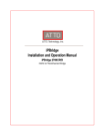
A survey made by Doulos Ltd. (a company offering training courses in SystemC) concerning the
question: “What are you using SystemC for, now in or in the future?” had the following results: the
current usage is concentrated to system optimization, high-level modelling and co-simulation.
A brief chart is showed below giving the most common usage of SystemC and its expected usage
in this project even though we will see later in details why SystemC is used in our case.
Our first goal will be to know what SystemC could bring new compared with a traditional flow: in
our case, the architecture exploration when designing a System-On-Chip (See 2.1.1 for its
definition) could be an interesting usage.
But on a first outlook, implementing a new transaction level modeling may be the most interesting
point since it will overcome the gap between RTL and TLM level.
Nicolas Lainé – TEC-EDM
2
Research on new SoC design Methodology using SystemC
issue 1 revision 0 -
Some new extensions from the standard C++ language were added such as:
Time notion
Parallel execution of entity called “Processes”
Introduction of data types
An entity can both describe a behaviour and hierarchy
Several models levels are used in SystemC to describe a component. The most important ones are
listed below:
•
•
•
Functional Model
Transaction Level Model (TLM)
Register Transfer Level (RTL) model
These models come with terms to characterize them:
• Untimed Functional (UTF)
UTF refers both the model interface and the model functionality. Time is not used for
execution.
• Timed Functional (TF)
TF refers to both the model interface and the model functionality. Time is used for
execution.
• Bus Cycle Accurate (BCA)
BCA refers to the model interface and not the model functionality. Timing is cycle accurate
and usually tied to a system clock. It does not infer pin level detail and transfer of
information is modeled as transactions.
• Pin Cycle Accurate (PCA)
PCA refers to the model interface and not the model functionality. Timing is cycle accurate
and tied to a system clock. It contains pin level detail.
• Register Transfer (RT) Accurate
Everything is fully timed with a complete detailed functional description for every clock
cycle.
What are the benefits to split into several models of hierarchy?
• First we can start to describe a design from a functional model, that means that only the
algorithm is described using a language (typically C++ language) and then can be used as a
golden reference or a starting point to our design flow. We can also leave from the TLM
model and always serves as an executable platform that is accurate enough to execute
software on.
•
Second and not the least, the fact to leave from the TLM model may significantly increase
the simulation speed compared with RTL model using typical hardware modelling
descriptions languages such as VHDL or Verilog, typically will increase by a factor of 300400 in terms of cycles per second for a standard System-On-Chip. TLM SystemC will serve
Nicolas Lainé – TEC-EDM
3
Research on new SoC design Methodology using SystemC
issue 1 revision 0 -
as a platform allowing for early software development and co-simulation of hardware and
software.
•
Finally SystemC can be also used for functional verification using the power of C++
language.
In conclusion, SystemC can have several models levels to describe the design and can be used both
for modelling and verification of a system. But when verification and implementation become very
important, an efficient methodology is required which involves the creation of a minimum number
of models.
To achieve this on complex designs with adequate simulation performance, high-level models are
not just needed to simulate the software on a model of the hardware, but also to accelerate the
process of modeling hardware IP in a bus independent.
1.2
Traditional system design flow
In traditional system design, architectural design and hardware design are separated from each
other.
In others words, a gap in the development process exists between modelling and Register Transfer
Level modelling. This “break” may introduce errors in the translation from functional
models to RTL models.
Nicolas Lainé – TEC-EDM
4
Research on new SoC design Methodology using SystemC
issue 1 revision 0 -
1.3
Design flow using SystemC
When starting from a very high abstraction level such as a functional model, we need to refine our
model to go through TLM models and finally to get a RTL model which can be synthesized and
them mapped into the final model which will be at gate level, typically written in VHDL or
Verilog.
1.4
Main SystemC concepts
Some basic concepts built specially for hardware design using C++ language are commonly
understood by the SystemC community. The main important entities are listed below.
Entity
Description
Module
Process
Hierarchical entity which contains other modules or processes
Describe the behaviour between modules. They are contained in the SystemC modules.
There are 3 different types of processes: SC_METHOD, SC_THREAD and SC_CTHREAD
Connections between modules. Could be either unidirectional or bi-directional
Supports resolved and non-resolved signals (resolved signals can be connected to
several sources, unlike non-resolved signals)
In order to support the modeling at many abstraction levels (from a functional level to
RTL level), SystemC library does support a large amount of port and signal types
Idem, required to grant all abstraction levels
Ports
Signals
Port and Signal
type
Data type
Nicolas Lainé – TEC-EDM
5
Research on new SoC design Methodology using SystemC
issue 1 revision 0 -
1.5
Modelling Overview
Then co-simulation is used if a SystemC testbench is used with a Verilog or VHDL design
representation.
A SystemC system consists of a set of modules interconnected at each other with channels. Inside a
module, we can find concurrent processes which describe functionality of the system. Inter-module
communication is also done with channels.
For each module, we need to specify ports to communicate through channels. Depending what the
module represents, the ports will represent the interface, pins and so forth.
An interface is a set of access methods. It does not provide any implementation but is purely
functional. Interfaces are bound to ports in a sense that they define what can be done through a
particular port. A process accesses the channel by applying the interface methods a port.
1.5.1
FUNCTIONAL MODELING
Nicolas Lainé – TEC-EDM
6
Research on new SoC design Methodology using SystemC
issue 1 revision 0 -
The behaviour of this model, at this level, is purely described algorithmically. The timing is not
cycle accurate but could describe the time to generate or consume data or to model buffering or
data access. The behaviour of the interface is entirely done by communication protocols.
The goal of this level modeling is first to validate the algorithm, however in my case, I did not
choose to start with this model. I started directly with TLM level because our first goal was to
show a new design methodology and not to design a new super efficient compression module.
1.5.2
TRANSACTION LEVEL MODELING
Instead of driving the individual signals of a bus protocol the goal is to exchange only what is
really necessary: the data payload. Data transfers are modelled as transactions (read/write
operations).
Characteristics of TLM level Model:
Model behaviour is either timed or untimed algorithmic descriptions
No pin level detail for interfaces
Cycle accurate or not depending upon the level of modelling desired
Since TLM model is not giving any pin level details for its interfaces, model descriptions are much
simpler and faster during simulation. The implementation is event-based that may be not clockdriven. When RTL level model is using hardware channels, TLM level model will use abstract or
elementary channels (such as sc_fifo) in its most primitive form, an implicit handshaking is done in
TLM level model for communication with external buses of the design.
Where as RTL level model uses explicit handshaking i.e. with the implementation of request and
acknowledge signals.
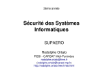
MODULE 1
Abstract channel
Process A
Nicolas Lainé – TEC-EDM
SC_FIFO
Process B
7
Research on new SoC design Methodology using SystemC
issue 1 revision 0 -
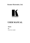
As specified by the name, TLM model is based on transaction monitoring and recording: a
testbench generates stimuli and sends them to the DUT (Design Under Test) without taking care
about communication implementation both entities.
TESTBENCH
SC_FIFO
MODULE 1
Design Under Test
SC_FIFO
TLM model will then be used for verification as previously seen as a golden reference: verification
will take place with comparison between results from golden reference model and refined model of
the DUT which could be either TLM or RTL level model.
Note that the refinement of the DUT also needs the introduction of adapters connected to the
testbench. However having a constant testbench is crucial for design exploration. Indeed if the
testbench is modified during the different steps of the design flow and if at the same time
some change is made to the DUT, then it is difficult to conduct reliable experiments.
We chose to start design flow of the lossless compression data module with the implementation of
this level.
Principal benefits that we can expect are:
♦ Faster compared to RTL models
♦ Simpler to design and set up during simulation
♦ Time-to-implementation reduced significantly
1.5.3
REGISTER TRANSFER LEVEL MODELING
RTL models will describe hardware and contain a full functional description of the algorithm,
moreover, every signals, buses and registers values are defined at every clock cycle. The main
difficult part when writing RTL code is to keep in mind that we have to write a synthesizable code.
Writing RTL style code in SystemC is quite similar to writing RTL code in either the Verilog or
VHDL hardware description languages.
Nicolas Lainé – TEC-EDM
8
Research on new SoC design Methodology using SystemC
issue 1 revision 0 -
1.6
Summary
SystemC provides an easy way to design at many levels of abstraction. It works perfectly for functional
modeling, as well as transaction modeling so that the move between modeling methods is made easier while
using the same language.
Moreover when switching to higher-level design descriptions, it will allow a greater performance in terms of
speed and flexibility.
Nicolas Lainé – TEC-EDM
9
Research on new SoC design Methodology using SystemC
issue 1 revision 0 -
2
DESIGN APPLICATION FOR SOC: DATA COMPRESSION
2.1
Objectives
2.1.1
REASONS TO LOOK FOR A NEW DESIGN METHODOLOGY
Complexity in microelectronics requires a different approach in the way to design ASIC or
System-On-Chip.
♦ What does “System-On-Chip” stand for?
System-on-a-chip (SoC) technology is the packaging of all the necessary electronic circuits and
parts for a "system" (such as a cell phone or digital camera) on a single integrated circuit (IC),
generally known as a microchip. For example, a system-on-chip for a sound-detecting device
might include an audio receiver, an analog-to-digital converter (ADC), a microprocessor,
necessary memory, and the input/output logic control for a user - all on a single microchip.
Today CMOS technologies like 90 nanometers allow reaching integration such as 50 Millions
gates on a die.
Starting from zero would represent an investment in time and debugging effort, an alternative
consist in making use of pre-checked module called IPs, for this purpose ESA had purchased a tool
(Magillem from Prosilog) allowing the integration and interconnection of IPs between them or to
different bus system (AMBA from ARM or CoreConnect from IBM).
A small SoC platform using this tool had already been designed at VHDL level and had been
implemented on a Xilinx breadboard.
The stage proposed will be directly linked to the previous development, and will consist in setting
up a SystemC application and map it to the existing SoC platform.
2.1.2
DIFFERENT STEPS
The algorithm of the application will have to be translated in SystemC at several levels of
abstractions, and then in a first time translate into synthesizable hardware language such as VHDL.
At the end of this task, we should map the full hardware application on to the SoC platform and we
should show some advantages of this new design methodology compared with normal design flow
described previously.
In the remaining time we will define the best suited partionning between hardware and software,
and perform the refinement steps to map the application on to the SoC platform.
Nicolas Lainé – TEC-EDM
10
Research on new SoC design Methodology using SystemC
issue 1 revision 0 -
The chosen application for this project is based on a lossless data compression dedicated for space
applications: Rice algorithm. It is an adaptive algorithm applicable to a wide range of digital data,
both imaging and non-imaging, recommended by CCSDS for lossless data compression on-board
spacecraft.
Only the encoder of this data compression algorithm will be mapped to the FPGA board, that’s why only this
part was implemented in several levels of abstraction regarding top-down architecture. However the decoder
has also to be designed in a high abstraction level (TLM Model in our case) for validation purpose.
For more convenience, the adopted design flow for this study is showed below:
TLM LEVEL
Golden Reference of
RICE encoder/decoder
SystemC TLM LEVEL
COMPARE
REFINEMENT
RTL LEVEL
Testbench
SystemC TLM LEVEL
Towards SoC
architecture
exploration (TLM
Model)
Adapters TLM->RTL &
RTL->TLM + Checker
RICE encoder
SystemC
RTL LEVEL
COMPARE
COMPARE
TRANSLATOR
Synthesizable
RICE encoder
VHDL
RTL LEVEL
Synthesis
GATE LEVEL
Gate Level (HDL)
TOP-DOWN
ARCHITECTURE
Towards SoC implementation (encapsulating OCP protocols)
Nicolas Lainé – TEC-EDM
11
Research on new SoC design Methodology using SystemC
issue 1 revision 0 -
As we saw previously it is not required to modify the testbench when refining the design under
test, even for the after-placed-and-routed design. Note that it is also possible to start to explore
some miscellaneous SoC architectures starting from the TLM level. In this case, system engineers
will not have to wait for the RTL level of the IP before looking for the best suited system-OnChip. In the SoC implementation, we will discuss in more details about TLM possibilities on a
system point-of-view.
2.1.3
DESIGN AND VERIFICATION TOOLS USED
The following tools have been used to implement and test the IP Rice encoder:
•
•
•
•
•
•
•
•
2.2
Textpad 4.7.3 ……………………………………………….……….…...…...Text file editor
Microsoft Visual Studio 6.0 ………………………………………...C/C++ design compiler
Mentor Graphics Modelsim v6.0d & v6.1 ……………….…C++/VHDL Waveforms viewer
SystemC-2.0.1 ………………………………………………...………………...C++ library
Prosilog SC2VHDL ……………………………………...RTL SystemC-to-VHDL translator
Prosilog Magillem v2.2 …………………………………………………IP Interconnect tool
Synplicity Synplify Pro 8.0 ………………………….………………………...Synthesis tool
Xilinx ISE 6.3i ………………………………...…...Place & route & board implementation
Algorithm of Rice compression
2.2.1
GENERAL
There are two classes of source coding methods:
Lossless and Lossy
Æ A Lossless source coding technique preserves source data accuracy and removes redundancy in
the data source. In the decoding process, the original data can be reconstructed from the
compressed data by restoring the removed redundancy; the decompression process adds no
distortion. This technique is particularly useful when data integrity cannot be compromised.
It has been suggested for many space science exploration mission applications either to increase
the amount of information return or to reduce the requirement for on-board memory.
The price to pay is generally a lower Compression Ratio, which is defined as the ratio of the
number of original uncompressed bits to the number of compressed bits including overhead bits
necessary for signalling parameters.
After compression has been performed, the variable-length output is then packetized using CCSDS
packet format. Then these packets will be transmitted through a space-to-ground communication
link to a data sink on the ground using a packet data system.
Nicolas Lainé – TEC-EDM
12
Research on new SoC design Methodology using SystemC
issue 1 revision 0 -
We chose this simple algorithm in our case in order to validate a new design methodology.
Consequently note that all details of this algorithm provided in the CCSDS report concerning
lossless data compression (cf. [2] and [3]) were not fully implemented (i.e. a specified resolution
for input data samples is required or also the fact that the CCSDS packet formatting module was
not done during the trainee period).
Æ A Lossy source coding method removes some of the source information content along with the
redundancy. The original data cannot be fully restored and data distortion occurs. However, if
some distortion can be tolerated, lossy source coding generally achieves a higher compression
ratio.
By controlling the amount of acceptable distortion and compression, this technique may enable
acquisition and dissemination of mission data within a critical time span.
We will not attempt to explain the theory underlying the operation of the algorithm in this report.
2.2.2
THE SOURCE ENCODER
The Lossless source coder consists of two separate functional parts: the preprocessor and the
adaptive entropy coder, as shown below.
2.2.2.1 Preprocessor
The preprocessor does a reversible function to input data samples x, to produce a preferred source:
Nicolas Lainé – TEC-EDM
13
Research on new SoC design Methodology using SystemC
issue 1 revision 0 -
δ = δ 1 , δ 2 ,...., δ i ,...., δ J
where each δi is an n-bit integer, 0 ≤ δi ≤ (2n–1). For an ideal preprocessing stage, δ will have the
following properties:
a) The {δi} is statistically independent and identically distributed.
b) The preferred probability, pm, that any sample δi will take on integer value m is a non-increasing
function of value m, for m = 0, 1, . . . (2n–1).
Its architecture can be summarized within the following schematic:
The preprocessor function is a reversible operation, and, in general, the best lossless preprocessor
will meet the above conditions and produce the lowest entropy, which is a measure of the smallest
average number of bits that can be used to represent each sample.
∧
∆ = xi − x i
⎧ 2∆ i 0 ≤ ∆ i ≤ θ
⎪
δ i = ⎨2 ∆ i − 1 − θ ≤ ∆ i ≤ 0
⎪ θ + ∆ otherwise
i
⎩
∧
∧
where θ = min( x i − x min , x max − x i ) with x min = 0 and xmax = 28 − 1 = 255 in our case.
We expect that for a well-chosen predictor, small values of |∆i| are more likely than large values; as
shown below, the PDF (Power Density Function) of delta values should reach its maximum value
for zero samples.
Nicolas Lainé – TEC-EDM
14
Research on new SoC design Methodology using SystemC
issue 1 revision 0 -
2.2.2.2 Adaptive entropy coder
The following schematic shows the architecture of the entropy coder which represents the main
part of the encoder engine:
Nicolas Lainé – TEC-EDM
15
Research on new SoC design Methodology using SystemC
issue 1 revision 0 -
The principle of this module is to choose the smallest compressed datas issued from the options
processes. A unique identifier (ID) bit sequence is attached to the code block to indicate to the
decoder which decoding option to use. Then we get final compressed datas.
We will not explain in depth each option but in the following table are some descriptions of each
option knowing that each of them is best suited for a special case of input data.
Note that each option is working on a block unit. Remember that a block of data is defined as a
set of J samples (sample’s resolution is fixed to 8 bits in this implementation).
Option name
Option Zero-Block
Option Fundamental
Sequence
Option 2nd extension
The Split-Sample options
No compression
Description
This option is chosen when one or more than one consecutive blocks are all null
samples blocks. Then the output value is roughly the number of consecutive
zero-blocks.
The most basic option consists of m zeros followed by a one when
preprocessed sample δi = m. A Fundamental Sequence is the concatenation
of J FS codewords.
Each pair of preprocessed samples in a J -sample block is transformed and
encoded using an FS codeword. Let δi and δi+1 be adjacent pairs of samples
from a J-sample preprocessed data block. They are transformed into a single
new symbol γ by the following equation.
(δ + δ i )(δ i + δ i +1 + 1)
γ = i +1
+ δ i +1
2
The kth split-sample option is obtained by removing the k least-significant bits
(LSBs) from the binary representation of each preprocessed sample, δi, and
encoding the remaining bits with an FS codeword (see figure 3-2). This
produces a varying codeword length. codewords for the current block of J
preprocessed samples are transmitted along with the removed LSBs, preceded
by an ID field indicating the value of k. This process enables the adaptation of
codeword length to source-data statistics.
If all above options were unsuccessful to get a smaller compressed data than
input data, then the input data is sent to the output without any modifications.
2.2.2.3 The coded output format
Once the best compression option was determined, we have to format the corresponding data to the
output. In our case, we chose to output with a 8-bits wide bus (which is the most common case for
IP output).
The formatting part is showed as below with the example of the split-sample option:
Nicolas Lainé – TEC-EDM
16
Research on new SoC design Methodology using SystemC
issue 1 revision 0 -
As the compressed data will be variable-length data, the encoder never knows in advance how big ,
in terms of number of output bytes, the compressed data will be and all we know is that the output
will be less than 132 bytes corresponding to the “No-compression option” in addition with 4 bytes
of Option-ID.
As we will see later on, formatting the variable-length data to the output will represent the main
issue in the implementation of the encoder; we can see through this example that we need to
store into a memory the next byte which will be sent to the output.
2.2.3
THE DECODER ENGINE
The decoder engine is composed of two main parts, as the encoder engine, a decoder module and a
postprocessor unit. The postprocessor performs both the inversion prediction and the inverse of the
standard mapper operation. A global system point of view is showed below:
2.2.3.1 The adaptive entropy decoder
Basically the selected code-option ID bits, which are at the beginning of the CDS, will be extracted
first. Then the following datas will be decompressed with the corresponding code-option ID and
then sent to the post processor to recover original datas.
Reminds that once the code-option ID was found in the compressed input datas, the decoder unit
still doesn’t know how big the compressed datas will be.
Nicolas Lainé – TEC-EDM
17
Research on new SoC design Methodology using SystemC
issue 1 revision 0 -
2.2.3.2 The postprocessor unit
The inverse mapper function can be expressed as:
ifδ i ≤ 2θ ,
⎧ δi
when δ i is even
⎪
∆i = ⎨ 2
− (δ i + 1)
⎪
when δ i is odd
2
⎩
if δ i > 2θ ,
^
⎧
⎪ δ i - θ when θ = x i − x min
∆i = ⎨
^
⎪⎩θ - δ i when θ = x max − x i
^
^
Where θ = min( x i − x min , x max − x i ) .
2.3
Implementations
2.3.1
IMPLEMENTATION IN TLM MODEL
2.3.1.1 Encoder
The implementation of the rice compression algorithm in this level was described previously
following a top-down approach. As mentioned earlier, the TLM level is very close (syntax
language speaking) from the pure Rice algorithm in C++; we’re just using a sub-library SystemC
which is well-tuned for hardware implementation. Data transfers are modeled as transactions such
as read and write.
Concerning read and write transactions, we chose to use blocking transactions instead of nonblocking transactions because it requires less communication handling.
Nicolas Lainé – TEC-EDM
18
Research on new SoC design Methodology using SystemC
issue 1 revision 0 -
Typically we declare the channel by sc_fifo <sc_uint < 8 >> CHANNEL1, it means a
FIFO channel of unsigned integers values of 8 bits each and the length of the FIFO is set to 16 by
default (so a FIFO size of 16x8 bytes).
Then if we want to read in this channel, first we need to check if the FIFO is not empty. By
declaring specialized port such as sc_fifo_in <sc_uint <8>> CHANNEL1_IN, the
SystemC code to access the FIFO in such cases may be:
if (CHANNEL1_IN.num_available() != 0){
data_in=CHANNEL1_IN.read();
}
else wait(CLOCK_PERIOD, SC_NS); // wait for one clock cycle if no
data in the input FIFO
Same thing for writing into a fifo using the following specialized port:
sc_fifo_out <sc_uint <8>> CHANNEL1_OUT
if (CHANNEL1_OUT.num_free() != 0){
CHANNEL1_OUT.write(data_out);
}
else wait(CLOCK_PERIOD, SC_NS); // wait for one clock cycle if no
more free spaces available in the output FIFO
We can see through this example one more advantage of using SystemC: TLM level authorizes
some methods calls such as the checking of the number of available samples for reading port and
number of free spaces for writing port.
As we saw previously, the encoder can be separated between 2 parts: the preprocessor and the
encoder. Below is reminded all the input/output of the encoder engine at TLM Level:
Name
Direction, Type
Description
enable_preprocessor
IN, < bool >
enable_encoder
enc_data_in
enc_data_out
enc_data_out_log_file
IN, < bool >
IN, sc_fifo_in<sc_uint<8>>
OUT, sc_fifo_in<sc_uint<8>>
OUT, sc_fifo_in<sc_uint<8>>
Enables the preprocessor part (one
delay predictor)
Enables the adaptive encoder part
Input data to compress (8 bits)
Output compressed data (8 bits)
Copy of the previous one (for dumping
file)
The top (which is defined as the definition of the “black box”) of the encoder is showed below in
details:
#include "../../global.h"
#include "preprocessor_gold.h"
#include "encoder_gold.h"
SC_MODULE(top_encoder_gold) {
// PORTS DECLARATION //
Nicolas Lainé – TEC-EDM
19
Research on new SoC design Methodology using SystemC
issue 1 revision 0 -
sc_in < bool >
sc_in < bool >
sc_fifo_in < sc_uint < 8 > >
sc_fifo_out < sc_uint < 8 > >
sc_fifo_out < sc_uint < 8 > >
enable_preprocessor;
enable_encoder;
enc_data_in;
enc_data_out;
enc_data_out_log_file;
// INSTANCIATION //
preprocessor_gold
encoder_gold
*PREP_GOLD1;
*ENCODER_GOLD1;
// INTERNAL SIGNALS && FIFO’S //
sc_fifo < sc_uint < 8 > >
prep_data_out;
// CONSTRUCTOR //
SC_CTOR(top_encoder_gold) {
PREP_GOLD1 = new preprocessor_gold("preprocessor_gold");
PREP_GOLD1->enable_preprocessor(enable_preprocessor);
PREP_GOLD1->prep_data_in(enc_data_in);
PREP_GOLD1->prep_data_out(prep_data_out);
};
}
ENCODER_GOLD1 = new encoder_gold("encoder_gold");
ENCODER_GOLD1->enable_encoder(enable_encoder);
ENCODER_GOLD1->enc_data_in(prep_data_out);
ENCODER_GOLD1->enc_data_out(enc_data_out);
ENCODER_GOLD1->enc_data_out_log_file(enc_data_out_log_file);
One internal fifo (called prep_data_out) is used to connect the preprocessor result to the
encoder stage.
The preprocessor will not be discussed in details here since its implementation was straight
forward following the CCSDS recommendation; it was designed as a one delay predictor (the
current data is saved and will be used at the next clock cycle.
The encoder part was, from far, the hardest and most design timing intensive module to implement:
as we have already seen why before, this module has to determine the best option for each input
block till the total number of blocks is reached.
I chose to split the encoder engine into 4 parts or processes since we’re working inside a module
(SystemC module is defined by the SC_MODULE macros or by explicitly deriving a new class
from sc_module). A process looks like normal C++ functions with slight exceptions. A process is
invoked by the scheduler based on its sensitivity list.
SC_MODULE (SystemC module)
encoder_gold
Nicolas Lainé – TEC-EDM
Actions (or processes)
Void init ();
This thread initializes the encoder like the no-compression option is chosen by default.
long int get_length_input_data ();
This function gives the total number of blocks to compress from the input uncompressed
file.
Void option ();
20
Research on new SoC design Methodology using SystemC
issue 1 revision 0 -
This thread is the main part of the module; for each option, the compressed data is
calculated, determines the best option and then calls the format_data function.
Void get_block (int&, int& ,sc_uint<NB_BITS> [ ]);
If the input FIFO is not empty, then this function will read at its interface the next block
(16 bytes in our case) stored in this FIFO.
Void format_data (int ,sc_biguint <J*NB_BITS> ,sc_biguint <J*NB_BITS+6>&,long&,
int&,int);
This function will encapsulate the compressed data with some header corresponding to
the best option ID.
Note that the function option is a thread, which means that it is executed only once during
simulation, that’s why most of them contain some loops (for instance, while….end while) and can
be easily clocked by inserting some WAIT statements.
As seen earlier, we chose to use blocking transactions (that means for instance that if you read one
input FIFO which does not have any data, simulation will stop automatically without finishing the
current thread or process unless you check that FIFO is empty and then you wait for its filling.
That may cause some difficulties concerning the last input data block to compress: if the encoder
does not know in advance how big the size of input data is, it will be stuck at the last block of data
and thus will not compress it. That’s why before starting compression, the encoder needs to check
the total length of input data in terms of block.
In order to compress a data block (16 samples of 8 bits each = 128 bits), we need to use big
unsigned integers instead of normal unsigned integers limited to 32 bits wide. Indeed before
determining the best option for each block, full data first is required.
The most difficult part in coding the TLM encoder was about the formatting part since the output
port is only 8-bits wide, the compressed data has to be divided (its length is an integer ranged
between 6 and 132 bits) into byte.
Compressed data block A
Output byte
Compressed data block B
Concatenation between
bits of blocks A & B
The problem comes from the fact that compressed data may be not a multiple of 8: in this
case we need to save the last bits (until 8 bits) and wait for the next data block, then this last byte
will be sent followed directly with the compressed data of the next block. That is why we need to
know the total input number of blocks to compress otherwise the last byte of the last block may not
be sent to the output.
2.3.1.2 Decoder
As seen before, the decoder is composed of a decoder engine and a postprocessor unit. The TLM
decoder interface is even simpler than TLM encoder interface:
Nicolas Lainé – TEC-EDM
21
Research on new SoC design Methodology using SystemC
issue 1 revision 0 -
Name
Direction, Type
Description
enable_decoder
dec_data_in
dec_data_out
IN, < bool >
IN, sc_fifo_in<sc_uint<8>>
OUT, sc_fifo_in<sc_uint<8>>
Enables the decoder & postprocessor
Input data to decompress (8 bits)
Output uncompressed data (8 bits)
Below are showed functions or processes used for the decoder and brief description of them:
SC_MODULE (SystemC module)
decoder_gold
Actions (or processes)
Void init ();
This thread initializes the decoder: no-compression option is chosen by default.
Void identif_option ();
This thread is determining the code option corresponding to the input data knowing that
the ID option is always at the beginning of a new CDS (Coded Data Set, compressed data
format). Then it calls the function decode_CDS to decode the current CDS with the
appropriate compression option.
Void decode_CDS(int, int& , sc_uint<NB_BITS> &, sc_uint<NB_BITS> [ ]);
It will decode the CDS with the corresponding option ID. The output of this function is the
output uncompressed datas stored in an array of unsigned integers of 8 bits each.
Void check_index (sc_uint <NB_BITS>&, int &);
If the bit index is 0, then we finished handling the current byte and we need to get one
new byte at the input. The bit index will be then set to 7.
The main difference in the TLM algorithm with the encoder is that here we are working with byte
to byte unlike the encoder with block to block. Indeed the decoder is not able to know in advance
the size of the input (=compressed) data.
2.3.1.3 Top and testbench
“top” is the use of both the encoder and the decoder in TLM level. It does consist of a main
function in SystemC which instantiates the encoder, decoder and testbench. In order to be able to
use our TLM level, we finally need to build the testbench which will have 2 goals: sends input
uncompressed data to the encoder and receives the output uncompressed data from the decoder and
then compares them.
The testbench has a fundamental goal here since it will be used again with the RTL
implementation of the encoder with some external refinement such as the introduction of adapters
between the testbench and the RTL design under test. We will come back later on about the
adapters when dealing with the TLM-RTL co-simulation.
#include "../global.h"
SC_MODULE(tb_encoder_both){
// PORTS
sc_out < bool >
sc_out < bool >
sc_out < bool >
sc_fifo_out < sc_uint < 8 > >
sc_fifo_out < sc_uint < 8 > >
sc_out < sc_lv < 16 > >
sc_in < bool >
Nicolas Lainé – TEC-EDM
reset;
enable_preprocessor;
enable_encoder;
data_in_tlm; // FIFO Out to the TLM Encoder
data_in_rtl; // FIFO Out to the RTL Encoder
nb_blocks_tocompress;
compression_end;
22
Research on new SoC design Methodology using SystemC
issue 1 revision 0 -
sc_fifo_in < sc_uint < 8 > >
data_compressed_log_file;
// THREADS
void
init ();
void
send_tlm ();
void
send_rtl ();
long int
get_length_input_data();
void
receive_data();
// INTERNAL SIGNALS
sc_string
input_file;
sc_string
output_file;
int
init_finished;
int
num_block_sent_tlm;
int
num_block_sent_rtl;
int
num_byte_received_from_tlm;
SC_CTOR (tb_encoder_both){
num_block_sent_tlm=num_block_sent_rtl=num_byte_received_from_tlm=init_finished=0;
input_file="../../../tests/uncompressed_datas.txt";
output_file="../../../tests/RTL_VHDL/compressed_datas.txt";
};
}
SC_THREAD (init);
SC_THREAD (send_tlm);
SC_THREAD (send_rtl);
SC_THREAD (receive_data);
Above is showed the testbench module declaration for TLM validation. However it will also be
used as testbench for the RTL encoder. First we can notice that there’s no clock timing introduced
in the ports definition but only an asynchronous reset port.
Basically the testbench is made around two main processes: send data to the encoder and then
receive its compressed data. Two test files need to be declared; one which contains input
uncompressed datas in a RAW format (i.e. each line is one byte in decimal value ranged between 0
and 255), the other one to store the resulting compressed data. Note finally that all functions are
used as threads (i.e. executed only once during simulation) and thus contain loops which will be reexecuted while there are still some data in the input file. Top level files can be found in Appendix
1.
2.3.1.4 Problems encountered
During the implementation of the Rice compression algorithm using TLM model in SystemC, we
were faced with some problems related to the following causes:
Æ Set up the environment
No problems related to the setup of SystemC. Nevertheless the UNIX Modelsim version rebooted
sometimes the computer for network slow response reasons (related to NFS Interdrive). I was
greatly dependent of the ESA network status, that’s why after that I decided to switch on windows
platform for debugging TLM Model.
Nicolas Lainé – TEC-EDM
23
Research on new SoC design Methodology using SystemC
issue 1 revision 0 -
Æ Limitation of debugging tools
Modelsim constraint: C debug is not really convenient (based on the old GDB UNIX debug tool),
it does have typical debugging commands such as setting breakpoints or stepping mode.
Nevertheless, speed of the debugger is limited by the Modelsim speed which is not really as big as
Visual C++ speed. We can explain this because Modelsim was designed first for hardware variable
types handling and not C++ variable types. That’s why I do not recommend the use of Modelsim
v6 or less to debug C++ entities.
Moreover, simulating TLM model using waveforms is possible but quite difficult when the design
is not clocked. A solution to bypass this problem is to introduce clock cycles in the design without
altering performance (i.e. simulation speed).
It can be done for instance by adding a “wait” line after each write at the output as written below:
output_port.write(output_port_tmp); // Write at the output of the IP
wait(CLOCK_PERIOD, SC_NS);
// WAIT statement for Modelsim debug
Finally there’s no way to display waveforms for local variables defined in a process. To resolve
this issue, the designer may need to define module member variables knowing that it may slow
down the simulation in Modelsim.
Visual Studio (Visual C++) constraint: One important limitation occurred when handling long
variables such as “sc_biguint” or “sc_bigint”. Indeed MS Visual Studio is limited with 32 bits
when trying to examine the values of these variables.
Æ SystemC bugs or missing parts in libraries
In the entire project, I used SystemC v2.0.1 and it suffered with few bugs or missing part such as:
•
Concatenation between sc_biguint and sc_uint not handled. This problem is fixed in
SystemC v2.1. I did not use this version since it was not provided with the Visual Studio
librairies.
2.3.2
IMPLEMENTATION IN RTL LEVEL OF THE ENCODER
2.3.2.1 TLM to RTL refinement
After validating the TLM level of the DUT, we need to refine our model into a synthesizable level:
which is the RTL level. Basically there are 2 types of refinement:
Refinement
Model refinement
Communication refinement
This ability to separate model refinement from communication refinement is a powerful
feature of SystemC.
Nicolas Lainé – TEC-EDM
24
Research on new SoC design Methodology using SystemC
issue 1 revision 0 -
In order to proceed there are several general areas to pay attention:
•
Algorithmic descriptions (untimed) need to be replaced with register transfer accurate
descriptions.
For example, if the root square C++ function: “sqrt” is used in the TLM level, it
needs to be replaced, or refined, with a collection of simple functions that can be
performed by an embedded microprocessor or directly implemented in hardware.
•
Abstract channels like sc_fifo need also to be changed with hardware channels such like
sc_signal
•
If some C++ data types are present, they need to be translated with SystemC data types (for
example: unsigned int may become sc_lv<32> to define a tristate bus.
•
User defined types (not used in the Rice TLM implementation) are not allowed anymore,
they also need to be replaced with SystemC types.
•
Thread (i.e. functions executed once during simulation) has to be replaced into Methods
(i.e. functions executed every time a signal in the sensitivity list is changing)
In my case, the biggest issue was to translate all transactional interfaces in TLM level (implicit
because the SystemC user doesn’t have to care about interface handling at this level) to an explicit
request/acknowledge handshake. That means that every sc_fifo ports will have to be replaced with
handshake signals such as:
Port Name
Clk
Resetn
data_ready_in
data_in
data_accept_in
data_ready_out
data_out
data_accept_out
Nbr_blocks_to_compress
Compression_end
Direction
IN
IN
Description
IP Clock
IP Asynchronous reset (negative edge sensitive)
COMMUNICATION “HANDSHAKE” PORTS
IN
IN
OUT
The Input initiator says if ready or not
Incoming datas (8-bits wide in our case)
The IP accepts or not incoming datas
OUT
OUT
IN
The IP has ready datas at the output
Outputting datas
The output receiver says if ready to receive datas or
not
PARAMETER PORTS
Total number of blocks to compress
Set to ‘1’ when all blocks have been compressed and
sent to the output
To handle this handshake communication, we need a new entity in our compression module which
will be dedicated to the IP’s interface. In our case, this job is carried out with a finite state
machine.
Nicolas Lainé – TEC-EDM
IN
OUT
25
Research on new SoC design Methodology using SystemC
issue 1 revision 0 -
2.3.2.2 Implementation of the RTL encoder
DATA_READY_IN
State Machine
(FSM)
DATA_ACCEPT_IN
DATA_ACCEPT_OUT
FSM_VALID_OUT
&
DATA_READY_OUT
ENC_DATA_VALID
ENABLE_PREPROCESSOR
STATE_OUT
ENABLE_ENCODER
ENABLE_FORMATTER
STOP_RUN
END_DATA_REACHED
Preprocessor
DATA_IN
(8)
Encoder
DATA_OUT
(8)
CLK
RESETn
COMPRESSION_END
NBR_BLOCKS_TO_COMPRESS
The RTL implementation shown above displays in a “black box” architecture all signals
(=connections) and ports for the encoder engine. The state machine will give the output for the
following register:
Output registers of STATE MACHINE
Name
Description
INTERNAL REGISTERS:
Enable_preprocessor
Enable_encoder
Enable_formatter
State_out
Fsm_valid_out
PORTS:
Data_accept_in
Data_ready_out
Enables the preprocessing stage
Enables the encoding stage (i.e. receiving data from preprocessor +
computing compression data)
Enables the formatting stage (i.e. format & send the compressed data to
the output)
current state
Enables to send data to the output (grant from the state machine part only
but need also the grant of the encoder part)
Handshake communication
Handshake communication
Also the output registers of the encoder unit:
Nicolas Lainé – TEC-EDM
26
Research on new SoC design Methodology using SystemC
issue 1 revision 0 -
Name
INTERNAL REGISTERS:
Stop_run
End_data_reached
Enc_data_valid
PORTS:
Data_out
Output registers of ENCODER
Description
Stops the RUN mode because either the encoder needs to send more
datas or it has to send zero-block option datas
Set to 1 once all input blocks were compressed
The encoder unit is ready to send compressed datas
Handshake communication
2.3.2.3 Description of the state machine of RTL encoder
The state machine designed here is a Mealy state machine structure since the output logic is a
function of the current state and a function of the inputs. In my case, I decided to build an explicit
state machine to make easier the synthesis; 9 states are in total and the state machine diagram is
showed below:
RESET
reset
From all states (except reset),
go back to SETUP when
compression_end is high
SETUP
!enc_data_valid OR
!data_accept_out
IDLE
SECOND
!stop_run OR
!data_accept_out
data_ready_in AND
data_accept_out AND !stop_run
!data_ready_in OR
!data_accept_out AND
end_data_reached
PREP
data_ready_in AND data_accept_out
FORMAT_ONLY
EXIT_RUN
FIRST
data_accept_out AND
stop_run
!data_ready_in OR
!data_accept_out
!stop_run
data_ready_in AND
data_accept_out
RUN
!data_ready_in OR
!data_accept_out
Nicolas Lainé – TEC-EDM
27
Research on new SoC design Methodology using SystemC
issue 1 revision 0 -
Basically the state machine set the IDLE mode when both preprocessor and encoder are not
working and the RUN mode is when both of them are working together following a pipelined
architecture.
When the IDLE mode is set, and, as soon as the input and output are ready to be sent and received
datas, we can switch to PREP mode and then FIRST mode which are corresponding to 2 clock
cycles latency due to handshake signals and the 2 pipelined-stages between the preprocessor and
the encoder.
While both inputs: data_ready_in and data_accept_out are still set to one during RUN mode, the
state machine will remain in this state. However, if one of these goes to ‘0’ , then we need to exit
the RUN mode and switch to EXIT_RUN mode and SECOND mode which will handle last current
data before finally going back to IDLE mode.
A dedicated state deals with too big compressed data at the output: FORMAT_ONLY mode; it is
also used for instance when the compressed data has not been entirely sent at the output while a
new block is arriving at the input. If this special mode is run then only formatting compressed data
(and sent it to the output) will work, not preprocessor and encoder.
2.3.3
CONCLUSION & FUTURE POSSIBLE IMPROVEMENTS
TLM implementation was much easier to design regarding the desired design flow: it can use
easily all C/C++ benefits. One of its great benefits is to get the model independent to
communications.
As the time ran fast during this project, I did not have time to implement entirely the Rice
compression following the CCSDS recommendation (cf. [2] and [3]). Below are listed some
missing parts or extensions which were not implemented knowing that the first goal of the
internship was to validate a new design methodology based on SystemC and not to get a complete
design of a compression algorithm, which already exists in the IP database of ESA.
•
•
•
•
•
Only RAW format accepted for input data file
Constant resolution (8 bits required), could be extended to 32 bits for instance.
Reference sample is missing
Remainder-Of-Segment ‘ROS’ is missing for the Zero-Block option
Data packetization module according to CCSDS-recommended data packet format. A preexisting IP for encapsulating CCSDS packet (PTME) is already on the ESA market.
Nicolas Lainé – TEC-EDM
28
Research on new SoC design Methodology using SystemC
issue 1 revision 0 -
2.4
Simulation and validation of the Design Under Test
2.4.1
DEBUG ISSUES
•
There is right now no debugger tool for SystemC-based module. To debug SystemC code,
we can use some new debugger such as DDD furnished with NC-Sim or internal debugger
in Modelsim. However it’s kind of difficult to debug using these tools in a quick way
without putting some flags like “cout” or “printf” in your code.
•
Moreover and as seen before there is no possibility to display local variables defined in a
process in waveforms since there are only defined during execution of the process.
2.4.2
TLM MODEL VALIDATION
2.4.2.1 Using Microsoft Visual Studio©
You can use Microsoft Visual C++ to design your SystemC module, before you need to set up the
tool for SystemC files:
Installing To Your Local Computer
1. The SystemC distribution includes project and workspace files for MS Visual C++. If you
use these project and workspace files the SystemC source files are available to your new
project. For Visual C++ 6.0 the project and workspace files are located in directory:
...\systemc-2.0.1b\msvc60 , where "..." is whatever parent directory you saved SystemC to.
2. Click on the subdirectory: `systemc' which contains the project and workspace files to
compile the `systemc.lib' library. Double-click on the `systemc.dsw' file to launch Visual
C++ with the workspace file. The workspace file will have the proper switches set to
compile for Visual C++ 6.0.
Select `Build systemc.lib' under the Build menu or press F7 to build `systemc.lib'.
Creating a new design
1. Start Microsoft Visual C++ 6.0
2. Create a Project Workspace:
a. Click on "File", then "New", select "Projects", then click on "Win32 Console
Application".
b. For the "Project Name", we will use "rice" as the example. Type “OK”
c. Choose "An empty project" and click "Finish". Then click "OK".
Nicolas Lainé – TEC-EDM
29
Research on new SoC design Methodology using SystemC
issue 1 revision 0 -
3. You can now see a folder named "rice classes" in the workspace window. (Left part of
screen)
4. Port SystemC libraries to Microsoft Visual C++ 6.0:
a. Click on “Project”, then “Settings”, then select the C/C++ tab, and then finally
select the “C++ Language” category. Make sure that the “Enable Run Time Type
Information (RTTI)” checkbox is checked.
b. Also make sure that the SystemC header files are included by switching to the
“Preprocessor” on the C/C++ tab and then typing “C:\SystemC\systemc-2.0.1\src”
in the text entry field labelled “Additional include directories”.
c. Next click on the “Link” tab, and make sure the SystemC library is included to your
project by typing “C:\SystemC\systemc-2.0.1\msvc60\systemc\Debug” in the text
entry field labelled “Additional library path”.
d. Add the SystemC object files by first clicking on “Project”, then “Add to Project”,
then “Files”. In the File Browser navigate to the “C:\SystemC\systemc2.0.1\msvc60\systemc\Debug” directory. In the text entry field labelled “File
Name” type “*.obj” and press enter. Click on the file “sc_attribute.obj” and then
simultaneously press the “Ctrl” & “A” keys (CTRL+A). Click the OK button to add
the files.
e. In your workspace window under the “File View” Tab, you should see a number of
object files with the “sc_” prefix such as sc_attribute.obj, sc_bit.obj, etc. Find the
file “sc_isdb_trace.obj”, click that file name, and press “delete” on your keyboard.
Nicolas Lainé – TEC-EDM
30
Research on new SoC design Methodology using SystemC
issue 1 revision 0 -
The main advantage in using MS Visual C++ for SystemC implementation is the debug mode: this
mode authorizes you to stop simulation whenever by introducing some breakpoints in the code.
However as Visual C++ was not originally built for hardware development purposes, it cannot
display waveforms such as tools like Modelsim or NC-SIM. So if you are using some timing
constraints in your TLM model, you may use Modelsim first.
That was the basic features of the debugger but you can also use more complex debug options if
you like: exceptions handling, thread suspension. Below are shown all actions or triggers you can
have during debugging:
For each statement in your code, you can either choose to go on to the next statement by choosing
“STEP OVER” function or step into the C function called by this statement if it was compiled
before by choosing “STEP INTO”.
2.4.2.2 Using Mentor Graphics Modelsim©
Modelsim implements also the SystemC language based on the Open SystemC Initiative SystemC
2.0.1 reference simulator. The main advantage compared with Visual C++ is the extensive support
for mixing SystemC, VHDL, and Verilog in the same design.
However, you will need to modify your SystemC source code to be simulated on Modelsim, below
are the main steps in order to get your first simulation of your design:
1
2
3
4
5
Create and map the working design library with vlib and vmap commands.
Modify your main SystemC source code:
• Replace sc_main() with an SC_MODULE
• Replace sc_start() by using the run command in the GUI
• Remove calls to sc_initialize()
• Export the top level SystemC design unit using the SC_MODULE_EXPORT macro
Compile all your SystemC source code with sccom command
Perform a final link of the C++ source using sccom –link
Simulate the design using vsim command and run the simulation using run command
Note that if you are choosing to work on both Modelsim and Visual C++, you can use the same file
for the top level design unit by specifying with the MTI_SYSTEMC macro the Modelsim specific
code.
Nicolas Lainé – TEC-EDM
31
Research on new SoC design Methodology using SystemC
issue 1 revision 0 -
2.4.3
RTL LEVEL VALIDATION
2.4.3.1 Testbench with several levels of abstraction
One of the biggest benefits to start from TLM level is the ability to use TLM entities with RTL
models. The next figure shows the environment around the testbench based on a comparison
between both levels of abstraction.
Note that it was not needed to refine the testbench into RTL model; the only refinement step is the
introduction of some adapters between TLM and RTL transactions.
ENCODER TLM
DECODER TLM
C
H
E
C
K
E
R
Testbench
TLM Model
A
d
a
p
t
e
r
Design Under Test
ENCODER RTL
A
d
a
p
t
e
r
DECODER TLM
TLM
Transaction
RTL
Transaction
The detail and source code of this testbench can be found in Appendix 3. Note also that a
Modelsim compilation script for this testbench can be found in Appendix 4.
2.4.3.2 Adapters needed for TLMÆRTL and RTLÆTLM
-
Adapter TLM Æ RTL
This adapter converts SC_FIFO signal to RTL handshake signals and can be directly used between
a TLM testbench and RTL DUT.
Nicolas Lainé – TEC-EDM
32
Research on new SoC design Methodology using SystemC
issue 1 revision 0 -
For the generation of handshake signals, a random function was used so that it can approximately
take care of busy states at the input. The average length in terms of clock cycle for gap (period
during data_ready_in will be high) and for burst (period during data_ready_in will be low) can be
selected by the user. However it will be necessary to recompile SystemC file after each
modification. See Appendix 2 for the source code of each adapter.
-
Adapter RTL Æ TLM
It converts RTL handshake signals from the IP to SC_FIFO signal. Both length average of gap and
burst can also be selected by the user. Note that also data_out is dumped into a file.
2.4.3.3 Checker to compare results between RTL and TLM
Nicolas Lainé – TEC-EDM
33
Research on new SoC design Methodology using SystemC
issue 1 revision 0 -
The checker compares results from TLM and RTL levels. Some extra signals are required for the
TLM decoder (two decoders: one for decoding TLM encoder data and the other one for the RTL
encoder). The compression_end signal coming from the RTL encoder will arrive as soon as the last
block of data was handled. If results are not the same, then stop_simulation will go high and may
be used for instance as a trigger to stop the simulation. A checker is not required in the validation
process but it is just a way to speed the verification up.
2.5
Translation RTL SystemC to RTL VHDL
2.5.1
GOALS
Following a typical top-down architecture using SystemC, after designing in RTL level with
SystemC the data compression encoder, the design flow requires the translation into RTL VHDL
for synthesize since up to now, no tool on the market is able to produce a netlist from SystemC
(even RTL based-code). Thus the following report part deals with:
Æ Replace the non-synthesizable SystemC code with synthesizable code for the Design Under Test module.
To translate SystemC to VHDL code, we chose to use a Prosilog tool: “SC2VHDL v1.0”
2.5.2
ISSUES AND RECOMMENDATIONS
During this translation we noticed some important points underlined below:
•
Short documentation concerning the tool
Nicolas Lainé – TEC-EDM
34
Research on new SoC design Methodology using SystemC
issue 1 revision 0 -
•
Bugs found in the translator and forwarded to the Prosilog support team, these bugs are :
1) Impossible to use arrays signals in several processes, a temporary solution is then to
replace this array by several signals for each process.
2) Incorrect translation of one internal loop in a loop when the first one depends on the
iteration variable of the second one; for instance:
for ( int i ; i < 10; i ++ ){
for ( int j ; j < 8-i ; j ++){
[…]
}
Recommendation to get correct RTL synthesizable codes
Indeed one of the biggest traps after designing in TLM level or higher abstraction level is that you
don’t respect RTL coding rules anymore. Thus when you are starting the translation to RTL level,
several modifications need to be done in the code.
Æ Non-constant variables used as parameters
In the “algorithmic version” (TLM Level for instance) we can design loops using non-constant
variables in parameters without any problems as shown below:
// length_tmp is non-constant variable (ranged between 0 and 8)
for ( int i = 0 ; i < length_tmp ; i++) {
MEM[i] = MEM_OLD[i];
}
However when switching to RTL level, the designer has to take care when using using nonconstant parameters in loops because it will not be synthesizable by commercial synthesis tool. The
previous code may be translated into this one:
for (int i = 0 ; i < 8 ; i++){
if ( i < length_tmp ){
MEM[i] = MEM_OLD[i];
}
}
Æ Local variables vs. member variables
One other trap is when using member variables in SystemC. SystemC distinguishes member
variables from member (or internal) signals where as VHDL does not! Thus if some member
variables are defined into a “SC_MODULE”, the SystemC-to-VHDL converter will translate them
into signals and they will be synchronous with the clock signal. However member variables in
SystemC are not synchronous with clock but are defined like local variables.
Nicolas Lainé – TEC-EDM
35
Research on new SoC design Methodology using SystemC
issue 1 revision 0 -
That’s why it is recommended to use local variables (defined in a process or function) rather than
using member variables defined in the SC_MODULE header. Moreover when more than one
process is accessing a member variable, it will not be synthesizable (use signals instead).
RTL SystemC using member variables
RTL SystemC using local variables (Better solution)
SC_MODULE(module_1){
SC_MODULE(module_1){
// PORTS DECLARATION
// PORTS DECLARATION
Sc_out < int > c;
// SIGNALS DECLARATION
Int b;
}
Void module_1::main(){
B = b + 1;
c.write(b);
}
Sc_out < int > c;
}
Void module_1::main(){
Int b;
}
B = b + 1;
c.write(b);
I notice that the translation inserted some type conversions in the VHDL code and after it requires
the pre-compilation of conversion functions (stored in prosilog_sc2v_conv.vhd package file). Note
that these conversion functions may slow down the simulation speed for the RTL VHDL code.
2.5.3
CONCLUSION ON THE TRANSLATION
The output of this experience is the following:
Name of the sub-module,
<file_name_systemc,file_name_vhdl>
FSM (Finite State Machine),
<fsm1.cpp, fsm1.vhd>
Preprocessor,
<preprocessor_gold.h, preprocessor_rtl.vhd>
Encoder Unit,
<encoder_gold.h, encoder_rtl.vhd>
Problem of
translation?
No
No
Yes
Output work
The RTL VHDL translation is up-todate with its SystemC counterpart
The RTL VHDL translation is up-todate with its SystemC counterpart
Due to some bugs of the translator
tool, the translation is not
straightforward and requires manual
modification after having translated
the VHDL output file.
Concerning the encoder unit, the translation is not “click & use” due to some bugs in the
SC2VHDL converter. Consequently a simple modification needed in the SystemC code may be
time consuming in some cases.
Nicolas Lainé – TEC-EDM
36
Research on new SoC design Methodology using SystemC
issue 1 revision 0 -
Modification in
RTL SystemC
code
C++ Compilation
Simulation with
testbench, RTL &
TLM SystemC
using MS visual
C++
Translation
using SC2VHDL
Simulation with
testbench, RTL
VHDL & TLM
SystemC using
Modelsim
YES
Do Results
match?
NO
A short draw is showed above mentioning previous steps concerning the refinement (or translation)
from SystemC to final synthesizable VHDL code.
2.6
Results
2.6.1
COMPRESSION RATIO
In order to get some figures about how powerful the compression algorithm is, we need to send big
amount of datas.
We chose to send raw data pictures to the encoder and then to decode it in order to find the original
data.
It was a good way to show the IP doesn’t have bugs anymore: indeed when you send a lot of datas,
you will increase the probability to find an error in the algorithm. It was also a good way to
compare simulation speed of TLM Level with RTL model.
In order to convert raw data file (ASCII format) into an input testbench file compliant with the
TLM testbench, a PERL script was built for format file conversion. PERL is a language very wellsuited for file management knowing that building your own input testbench will take more time
and would restrict test cases.
A well-suited output parameter to appreciate the compression power is the compression ratio CR
defined by the ratio of the number of bits per sample before compression to the encoded data rate,
so for the Lossless compression algorithm applied with the entire datas to compress:
CR =
nJ × NumberOfBlocks
TotalLengthOfCompressedDatas
where n is the sample resolution and J is the block size.
Nicolas Lainé – TEC-EDM
37
Research on new SoC design Methodology using SystemC
issue 1 revision 0 -
Picture
spot-la_b1.raw
spot-la_b2.raw
spot-la_b3.raw
spot-la_panchr.raw
Lena512
Size of
picture
Compression
ratio
250kBytes
250kBytes
250kBytes
1 Mbytes
262kBytes
1.496
1.507
1.558
1.653
1.582
Simulation
speed RTL
SystemC
58”
59”
56”
2’32”
1’06”
Simulation
speed RTL
VHDL
1’30”
1’31”
1’30”
5’20”
1’35”
Speed Gain
Factor
x1.6
x1.54
x1.61
X2.1
x1.44
Above is showed some results on the compression ratio obtained from typical space pictures and
the traditional “LENA” picture. The first 3 space pictures represent a satellite view of an urban
area; it means that these pictures should be quiet difficult to compress with an excellent
compression ratio compared with star pictures for instance.
Concerning the simulation speed, it was carried out with the testbench sending datas both to TLM
and RTL encoder & decoder plugged to a checker for comparing results from both sides. It is
important here to note that these tests were performed on Modelsim v6.1. In a first experience, we
compared simulation speeds between RTL SystemC and VHDL. SystemC offers greater speed
even though it was not as big as expected.
Typically the CR obtained here is very similar as expected despite some compression algorithm
features related to the CCSDS recommendation were not implemented (see 2.3.3 Conclusion and
future possible improvements).
2.6.2
COMPARISON TLM SYSTEMC VS. RTL VHDL
As we have seen earlier, one good thing to use intermediate level such like TLM allow designers to
either explore new architectures for the system or start earlier SW/HW partitioning. In the
traditional flow, people need to “wait for” the validation of RTL level before doing these
optimizations. In this case, it will be interesting to compare simulation speeds between TLM
(SystemC) and RTL (VHDL).
Picture
spot-la_b1.raw
spot-la_b2.raw
spot-la_b3.raw
spot-la_panchr.raw
Lena512
Size of picture
Simulation speed
TLM SystemC
250kBytes
250kBytes
250kBytes
1 Mbytes
262kBytes
18”
14”
15”
46”
16”
Simulation
speed RTL
VHDL
1’30”
1’31”
1’30”
5’20”
1’35”
Speed Gain
rate
x5
X6.5
X6
X7
X6
Results show that higher abstraction levels have a clear speed advantage. The biggest difference
in speed comes from the use of abstract timing in the communication, instead of using cycleaccurate communication.
Nicolas Lainé – TEC-EDM
38
Research on new SoC design Methodology using SystemC
issue 1 revision 0 -
However the results showed above, performed on Modelsim v6.1, are not really big as expected.
First it can be explained by the fact that rice compression implementation is based on a simple
communication scheme; a more complex communication implementation, such as a bus, would
most likely increase the speed difference considerably.
Finally one other factor may be the complexity of the model itself; a model with more complex
parallel processes would also increase the speed of abstract timing. For instance, the TLM model
of the Rice decoder is based on a complex main thread, one possible improvement should be to
split this one into small concurrent threads.
Note that these results may have to be minimized since the RTL VHDL contains some conversion
functions produced by the translator tool. Thus a comparison with RTL VHDL written by hand
(i.e. without any use of conversion functions) would have given higher speed for VHDL but will
be still lower than TLM SystemC! Unfortunately time was missing to implement by hand a VHDL
code for the Rice encoder.
2.6.3
SETTING TIME OF THE DIFFERENT STEPS
One goal of this study was also to show a faster design time using the new design methodology,
thus below it is displayed roughly the time rate for each design flow steps I spent (discarding
documentation reading and report writing time):
Design flow step
Time rate overall 1st period project
SystemC TLM Encoder and Decoder (coding & validation)
SystemC RTL Encoder (coding & validation)
Refinement for the translation to RTL VHDL Encoder
Synthesis + validation
30%
40%
20%
10%
The refinement TLM-to-RTL for the encoder was not straight forward (see 2.3.2.1 TLM to RTL
Refinement); since the TLM level does not include any timing issues and uses only abstract
channels for communicate, the biggest issue was the implementation of an explicit state machine.
Note that the first aim of a higher abstraction model here was to validate the algorithm.
However besides once the TLM model of the encoder was done, in a more complex and reliable
project, the high abstract level of the IP would have been given to the system engineer, in
charge of interconnecting each IP on the SoC bus and exploring the miscellaneous
architectures.
Nicolas Lainé – TEC-EDM
39
Research on new SoC design Methodology using SystemC
issue 1 revision 0 -
3
IP’S IMPLEMENTATION ON THE EXISTING SOC
3.1
Goals
Once the IP was implemented and tested using the new design methodology, we needed validate
the IP in a higher system level, thus the first step was to check if the IP could work correctly when
implemented in a System-On-Chip.
One important goal of this part of the project is also the possibility to interface the IP with one of
the most common IP interface protocol: OCP. See section 3.3.1 for details concerning the interface
encapsulation.
♦
♦
Encapsulation using OCP interface
Set-up of a System-On-Chip implementation according to the Rice encoder using
Magillem (Prosilog)
Implementation on the FPGA board
♦
3.2
Presentation of the IP interconnection tool: Magillem v2.3
(Prosilog)
3.2.1
TOOL PURPOSE
The aim of this tool is to interconnect IP or entities dedicated to be mapped on a System-OnChip, so that the designer is not taking care of interface connection between IP and bus
controllers anymore.
A library is furnished with the tool consisting of several VHDL files for special interfaces
protocols such as OCP Master/Slave protocols or the widely used AMBA bus controller interface.
Note that some TLM sources files are available also with the implementation of adapters (or
bridge) OCP protocols to TLM FIFO signals.
3.2.2
BUGS OR MISSING PARTS REPORTED
These problems had been seen on the v2.3 of Magillem:
-
When two IP’s are connected at each other with port A (STD_LOGIC) for the first IP
and port B (BIT) for the 2nd one, type’s conversion are not automatically done when the
top VHDL testbench is generated by Magillem.
-
In the AMBA Verification Platform, the mask “BE” is not working properly.
Nicolas Lainé – TEC-EDM
40
Research on new SoC design Methodology using SystemC
issue 1 revision 0 -
3.3
-
When an 8-bits output port is connected to one other IP to a 32-bits input port, the 24
highest bits are not set to 0.
-
When importing the top VHDL Leon3 with “Multi IP” button, some signals appeared
twice in the generated VHDL testbench file.
OCP Interface implementation for IP Rice
3.3.1
IP CREATOR TOOL
The new design methodology using SystemC has one other important key: the designer is still
building an IP with an IP re-use mind after. A tool from Prosilog “IP Creator” is able to generate
the source code in RTL level of the IP with a OCP corresponding interface. OCP is AMBA bus
compliant; meaning that it can be connected directly to one AMBA bus controller.
The user can choose define the IP top-level-name (Interface + IP), the FIFO depth in number of
bytes, clock synchronous or not, and, finally the IP ports definition; you can either specify if the
port is a IP special port (Control or Status registers) or a specific FIFO port such as din_accept or
din. Then the user just needs to press the button to get the corresponding VHDL (and Verilog)
source files.
Nicolas Lainé – TEC-EDM
41
Research on new SoC design Methodology using SystemC
issue 1 revision 0 -
3.3.2
IMPLEMENTATION AT RTL LEVEL
The OCP implementation carried out for this project is showed above. The compression IP is surrounded by two main FIFO-like interfaces,
one for sending uncompressed data to the IP (OCP MASTER IN) and the other one for receiving compressed datas from the IP (OCP
MASTER OUT).
These interfaces were generated from IP Creator© tool from Prosilog (cf. 3.4.1 IP Creator tool). This tool was easy to use; mainly
because the user just needs to specify if he wishes a Master_in or a Master_out, which kind of interface (either Memory-like or Fifo-like),
and finally the size of every config registers. Once this step is done, we have to define corresponding IP ports.
Nicolas Lainé – TEC-EDM
42
Research on new SoC design Methodology using SystemC
issue 1 revision 0 -
The user has also the possibility to define an internal IP to one OCP Master (for example OCP
MASTER IN), but in our case the IP is defined externally to the OCP if someone wants later
connect the Rice IP to one other interface protocol.
Æ How does each interface work?
The OCP MASTER IN does contain an OCP master block (OCP data port) generating external
data READ requests, a master FIFO module storing the data read and one OCP Target block used
for configuration port (OCP configuration port). It is able to access any memory independently to
perform READ transfers on the bus, in order to feed the IP with uncompressed datas.
The advantage of this interface is that the access to the memory does not require a host processor;
that’s basically what we call the DMA protocol (Direct Memory Access), used by each OCP
Master interface. The OCP MASTER OUT is quite similar as the input interface. For each
interface, the size of the FIFO was set to 64 bytes-length.
Since the Compression IP accepts data of 8 bits wide and that each transaction on the data bus is 32
wide, the FIFO module in each interface has been modified to make the conversion 32 bits -> 8
bits and 8 bits -> 32 bits (with the introduction of a state machine in each interface).
Below is displayed the configuration registers for each OCP Master unit; these registers can be
directly overwritten by a host processor or even a GUI or API for debug purposes. Note that these
values were optimized for a compression of picture of 15625 blocks (=250kBytes). Knowing that
the OCP transaction unit is a word of 32 bits, one input block would composed of 4 words each.
Start address
End Address
Transfer Length
Mode
Address Increment
Burst Length
Threshold register
3.3.3
OCP_MASTER_IN
OCP_MASTER_OUT
0x00004000
0x00005FFF
15625*4 =62500 words
Wrap addressing inactive, Transfer
length limited
4
8 bytes (1/2 block or 2 words)
5 : Number of empty slots (bytes) in the
FIFO after which OCP read request are
activated
0x00006000
0x00007FFF
Infinite
Wrap addressing inactive, Transfer
length unlimited
4
1 byte
1 : Minimal number of data received
by FIFO before activation of OCP
request
AT TLM LEVEL FOR VALIDATION PURPOSE
One other possibility in the new design flow is, once the TLM IP level is done and validated,
engineers can directly go through SoC architecture exploration and HW/SW partitioning without
waiting for the RTL IP design. This is one of the biggest advantages of designing a higher abstract
level. However the introduction of TLM level in a pre-existing RTL level design requires the
introduction of adapters as seen previously.
Nicolas Lainé – TEC-EDM
43
Research on new SoC design Methodology using SystemC
issue 1 revision 0 -
data_ready_in
data_in
Adapter
IN (RTLto-TLM)
FIFO
RICE IP (TLM
level)
FIFO
data_accept_in
Adapter
OUT
(TLM-toRTL)
data_accept_out
data_out
data_ready_out
OCP MASTER
IN
OCP MASTER
OUT
OCP Protocol (Master & Target)
OCP Protocol (Master & Target)
AMBA BUS
IP
3.4
Host
RAM
SoC design using Magillem
3.4.1
ONE SIMPLE EXAMPLE OF SOC USING THE RICE IP
Nicolas Lainé – TEC-EDM
44
Research on new SoC design Methodology using SystemC
issue 1 revision 0 -
The SoC source files can be found in the directory /work/src/SoC/leon_RB32_sram. A SoC was
designed in order to validate the new design methodology; both TLM and RTL Rice
implementations were successfully connected to a RTL VHDL SoC. The core of the SoC is the
AMBA bus controller; it does consist of a router which handles requests from a master and sends it
to the slave. The host is a widely used processor in space applications: Gaisler LEON3 [4].
It is a 32-bit processor core conforming to the SPARC-V8 architecture [5]. It has been designed for
on-board applications, and has high performance with low power consumption. Moreover it has
two main units: integer and floating-point unit, but, in our case only the integer unit will be used.
Then the controller receives the corresponding response of the slave. The following table gives the
main steps when compressing an input datas. We will assume in this case that external SRAM is
already filled with uncompressed (input) datas.
1
2
3
4
5
Leon reads its microcode stored into the OCP PROM
Leon configures both OCP IP’s interfaces for direct memory access to the SRAM
OCP MASTER IN reads from the memory controller input datas and sends it to the Rice
IP
OCP MASTER OUT writes to the memory controller output (compressed) datas from
the Rice IP
Once all input datas were compressed, the Rice IP sends an interrupt to the Leon so
that the host knows when to reset the IP interface for new optional datas
Nicolas Lainé – TEC-EDM
45
Research on new SoC design Methodology using SystemC
issue 1 revision 0 -
3.4.2
SOC USING RICE IP COMBINED WITH A SPACEWIRE
In the last SoC, we assumed that SRAM was already preloaded with the correct uncompressed
datas before starting compression. Since it will not be the truth in the reality, we would like to use
a spacewire (SPW) to handle loading SRAM. SpW is a high-speed serial link to transmit and
receive packets of data containing AHB and APB interfaces.
First we load the CHIP RAM with the microcode (software) used by the microprocessor LEON3;
this step will be done by the SpaceWire. Then the SPW will load the SRAM with the
uncompressed data loaded from the external SPW link. The compression Rice IP will then
compress data and stores compressed data straight into the SRAM. Finally Leon3 will pick these
data up, to give it to the SPW connected to the external link.
To simulate external SPW link, we used one other SoC based on a GUI initiator associated with a
SpW from the University of Dundee. The goal of this initiator was to send datas to the SpW
initiator (SpW UoD): sending the software, or the microprocessor application code, to the chip
ram, and then sending uncompressed data to the SRAM.
This SoC design was designed to validate the following points:
• Validation of the RICE IP on a SoC implementation
Nicolas Lainé – TEC-EDM
46
Research on new SoC design Methodology using SystemC
issue 1 revision 0 -
•
•
•
Validation of the Memory Controller combined with external SRAM
Use the Spacewire as a way to communicate with the board using high-speed link
Switching to a new trap table for the Leon3 and using a new microcode stored in chip
ram during its run.
After having implemented
the system-on-chip on the
FPGA board, sending
datas to the board is used
with a Spacewire link
connected to a Spacewire
portal which provides
remote access from a
transparent
Ethernet
interface
so
that
SpaceWire packets can be
directly sent and received
over Ethernet via a TCP/IP
socket connection (can be
simply the PC lab in our
case). There is no limit to
the
length
of
the
SpaceWire
packets
transferred.
3.5
FPGA Implementation
We may have three different possibilities after having mapped the System-On-Chip on the board:
Loading the software using:
• UART connexion (UART1) from a boot flash.
• UART connexion from Linux platform
• Debug Support unit furnished with the Leon3 library
The first possibility was used for the implementation. Below is showed a simple description of the
download application environment. A tool provided by Xilinx, called Impact, downloaded the
corresponding program to the FPGA.
Nicolas Lainé – TEC-EDM
47
Research on new SoC design Methodology using SystemC
issue 1 revision 0 -
PC1
Windows
1
Boot
PC2 Linux
UART2
3
FPGA Virtex E-XCV2000E
A
H
B
MEMORY
S
R
A
M
CTRL
C
o
n
t
r
o
l
l
e
r
LEON3 Core
RAM &
PROM
Debug I/F
Debug
Support
Unit (GDB)
2
3.6
Results
One implementation was done on a FPGA Virtex-E XCV200E running at 10 Mhz in a first try.
Unfortunately and due to lack of time (the breadboard implementation part began only two weeks
before the end of the stage), the compression was not completely successful even through all the
steps before reading from the SRAM was completely working. The problem may come from the
pinning associated to the SRAM and the configuration of the memory controller. But still some
datas were sent back by the Compression IP and the SpW!
However the post-place and route simulation was working well and compression was done
with 10 Mhz for the system clock and 40 Mhz for the SpW transfer clock. To check if
compressed datas were correct, SystemC was still used in decoding these datas using the
TLM decoder in order to retrieve original datas.
3.7
Possible improvements
-
Partitioning between software & hardware the Rice encoder:
For instance, the formatting part in the encoder unit could be carried out with the LEON3
processor (stored into the PROM). The resulting effect will be an increase of the clock frequency
since the formatting part may be software-oriented. However, due to the lack of time, this part
could have not been done during the project.
Nicolas Lainé – TEC-EDM
48
Research on new SoC design Methodology using SystemC
issue 1 revision 0 -
4
CONCLUSION
4.1
Results regarding specifications
4.1.1
STEPS REACHED
At the end of the study, a complete system design flow with SystemC has been established. In
more details, the following steps were successfully accomplished:
•
•
•
•
•
•
•
TLM model of the Rice compression algorithm (encoder and decoder)
Set up the testing environment (testbench and test I/O files, debug tools)
Refine by hand the encoder in a RTL model
Set up the dual-abstraction levels simulation
Validate the lossless data compression IP
Implement a System-On-Chip with the OCP-interfaced IP combined with a SpaceWire
for data transfers. Post-Place&Route Simulation was successful.
Writing a full documentation about the details of the new design methodology and
provide easy-to-use source files (VHDL, SystemC environments for the compression IP
and the resulting System-On-Chip
4.1.2
BENEFITS OF THE SYSTEMC DESIGN METHODOLOGY
¾ The development of SystemC for system modeling and design is something enabling
technology for top-down, iterative system design. Also the development of the
communication layer in SystemC along with the corresponding RTL model has given
SystemC an effective means of expressing designs at several levels of abstraction.
¾ TLM implementation proved to be a nice technique to overcome the gap present in the
traditional design flow between algorithmic and RTL models. All benefits that SystemC
brings may open doors to improved architecture exploration and performance optimization
sooner during the project elaboration with better performance.
4.1.3
POINTS TO BE STILL CLARIFIED
¾ The notion of TLM Level is not really clear: it can include several models depending on the
abstraction degree. For instance we can split TLM regarding if the design is either untimed
or timed. It has to be standardized for creating some specific models in order for people to
be able to build IP that they can exchange.
¾ The translation “by hand” from TLM level to RTL design is not straight forward and may
go up the duration of the project. A solution to this could be a design flow around a highlevel synthesis (cf. 4.2 What next?).
Nicolas Lainé – TEC-EDM
49
Research on new SoC design Methodology using SystemC
issue 1 revision 0 -
4.1.4
PROJECT TIME ORGANIZATION
Below I showed the approximate project time organization between April 2005 and September
2005. The main part was concerning the research on the new design methodology with the
implementation of the Rice compression IP.
25
20
DEFINITION AND SETUP
PHASE
15
DESIGN METHODOLOGY
STUDY
SYSTEM-ON-CHIP
IMPLEMENTATION
10
SUPPORT
5
0
Apr-05
May-05
Jun-05
Jul-05
Aug-05
Note that the System-On-Chip implementation could have been started earlier since the TLM
encoder model was ready at the end of April 05 (see Appendix 7). The support part dedicated to
report and PowerPoint writing started approximately at half-project time.
4.2
What next?
Æ SystemC v2.1
Imports interesting new features vs. previous versions:
• New class allowing multiple outstanding events like Verilog’s scheduled events.
• New facility which allows a module to expose internal channels
Æ High-level synthesis
Some new tools available on the market:
Towards algorithmic synthesis:
Catapult-C (Mentor Graphics)
CoWare’s SystemC-based ESL design
Celoxica for SystemC synthesis
These synthesis tools perform some new features such as
• Scheduling and resource allocation: the algorithm model is encapsulated in a module
whose communication protocol is represented either in a communication class or directly as
a signal-level handshake.
Nicolas Lainé – TEC-EDM
50
Research on new SoC design Methodology using SystemC
issue 1 revision 0 -
•
•
Creates a state machine and data path
Schedule functional units for the data path appropriately using control logic, satisfying area
constraints and latency constraints.
However latency and area cannot be determined until the design has reached the RTL or netlist
stage. With the new high level synthesis tool, backing up after the translation to RTL has been
made.
A high-level synthesis technology may bridge the gap between a GPL representation and an HDL
representation (including also the gap between algorithmic level and register-transfer level). It will
improve both the time-to-market and the quality of the target design.
Nicolas Lainé – TEC-EDM
51
Research on new SoC design Methodology using SystemC
issue 1 revision 0 -
AHB
APB
AMBA
BCA
CCSDS
CPU
DMA
DUT
ESA
ESTEC
ESL
FSM
FPGA
GUI
IC
OSCI
OCP
PCA
RTL
SOC
SPW
SRAM
TF
TLM
UTF
Nicolas Lainé – TEC-EDM
: Advanced High-Performance Bus
: Advanced Peripheral Bus
: Open standard, on-chip bus specification
: Bus Cycle Accurate
: Consultative Committee for Space Data System
: Central Processor Unit
: Direct Memory Access
: Design under Test
: European Space Agency
: European Space Research and Technology Centre
: Electronic System Level
: Finite State Machine
: Field Programmable Gate Array
: Graphical User Interface
: Integrated Circuit
: Open SystemC Initiative
: Open Core Protocol
: Pin Cycle Accurate
: Register Transfer Level
: System-On-a-Chip
: Spacewire ESA’s IP
: Static Random Access Memory
: Timed Functional
: Transaction Level Modeling
: Untimed Functional
52
Research on new SoC design Methodology using SystemC
issue 1 revision 0 -
[1]
S. Swan et al. SystemC v2.0.1 Users Guide, 2002.
http://www.systemc.org/projects/sitedocs/document/v201_Users_guide/en/1
[2]
Lossless Data Compression. Report Concerning Space Data Systems Standards, CCSDS
120.0-G-1. Green Book. Issue 1. Washington, D.C.: CCSDS, May 1997
[3]
Lossless Data Compression. Report Concerning Space Data Systems Standards, CCSDS
120.0-B-1. Blue Book. Issue 1. Washington, D.C.: CCSDS, May 1997
[4]
Björn Jonsson. A JPEG Encoder in SystemC. Thesis report
[5]
Doulos Ltd. . Fundamentals of SystemC, version 3.3. Golden Reference Guide Release 1.1
May 2002. http://www.doulos.com
[6]
Jiri Gaisler. LEON3 Processor User’s Manual. Gaisler Research 2004.
[7]
SPARC International Inc. . The SPARC Architecture Manual, Version 8. Revision
SAV080SI9308.
[8]
Prosilog. Magillem 2.1 SystemC Tutorial. September 2004, Ver. 1.0e.
http://www.prosilog.com
[9]
Prosilog. Prosilog SystemC Compiler, User’s Guide. Version 1.0. http://www.prosilog.com
[10]
Alan Ma and Allan Zacharda. SystemC Utilizing SystemC for Design and Verification.
http://www.model.com
Nicolas Lainé – TEC-EDM
53
Research on new SoC design Methodology using SystemC
issue 1 revision 0 -
Appendix 1
Appendix 2
Appendix 3
Appendix 4
Appendix 5
Appendix 6
Appendix 7
: Top files for the Rice encoder: TLM and RTL SystemC
: Adapters TLM->RTL, RTL->TLM
: Top SystemC testbench TLM/RTL results comparison
: Compilation script for the System-On-Chip used by Modelsim
: Synthesis script for the System-On-Chip used by Synplify
: Hierarchy diagram
: Detailed time organization chart
Nicolas Lainé – TEC-EDM
54
Research on new SoC design Methodology using SystemC
issue 1 revision 0 -
Appendix 1: Top entities for TLM and RTL Rice encoder in SystemC
TOP TLM Rice Encoder [SystemC]
/********************************************************************
* TLM Model of Rice compression IP - SystemC Model
* N. Laine
*
*********************************************************************/
*
#include "../../global.h"
#include "preprocessor_gold.h"
#include "encoder_gold.h"
SC_MODULE(top_encoder_gold) {
sc_in < bool >
sc_in < bool >
sc_fifo_in < sc_uint < 8 > >
sc_fifo_out < sc_uint < 8 > >
enc_data_in;
enc_data_out;
enable_preprocessor;
enable_encoder;
// ONLY FOR DEBUG PURPOSE //
sc_fifo_out < sc_uint < 8 > >
enc_data_out_log_file;
preprocessor_gold
encoder_gold
*PREP_GOLD1;
*ENCODER_GOLD1;
sc_fifo < sc_uint < 8 > >
prep_data_out;
SC_CTOR(top_encoder_gold) {
PREP_GOLD1 = new preprocessor_gold("preprocessor_gold");
PREP_GOLD1->enable_preprocessor(enable_preprocessor);
PREP_GOLD1->prep_data_in(enc_data_in);
PREP_GOLD1->prep_data_out(prep_data_out);
ENCODER_GOLD1 = new encoder_gold("encoder_gold");
ENCODER_GOLD1->enable_encoder(enable_encoder);
ENCODER_GOLD1->enc_data_in(prep_data_out);
ENCODER_GOLD1->enc_data_out(enc_data_out);
ENCODER_GOLD1->enc_data_out_log_file(enc_data_out_log_file);
}
};
TOP RTL Rice Encoder [SystemC]
/********************************************************************
* RTL Model of Rice compression IP - SystemC Model
* N. Laine
*
*********************************************************************/
*
#include "systemc.h"
#include "fsm1.h"
#include "preprocessor_rtl.h"
#include "encoder_rtl.h"
SC_MODULE(top_encoder_rtl) {
//// PORTS /////////////////
sc_in < bool >
clk;
sc_in < bool >
reset;
// Asynchroneous reset
sc_in < bool >
data_ready_in;
// Ready signal to receive input datas
sc_out < bool >
data_accept_in;
// Grant signal to receive input datas
sc_in < sc_lv < 8 > >
data_in;
// Input datas bus (8 bits)
sc_out < sc_lv < 8 > >
data_out;
// Output datas bus (8 bits)
sc_out < bool >
data_ready_out;
// Ready signal to send output datas
sc_in < bool >
data_accept_out;
// Grant signal to send output datas
///// CONTROL & STATUS REGISTERS ///////
sc_in < sc_lv < 16 > >
nb_blocks_tocompress; // Number of blocks to compress
sc_out < bool >
compression_end;
// set to '1' when all input datas
were compressed and sent to the output
////////////////////////////
///// INTERNAL SIGNALS /////
sc_signal < bool >
sc_signal < bool >
sc_signal < bool >
sc_signal < sc_lv < 8 > >
sc_signal < bool >
sc_signal < bool >
sc_signal < bool >
sc_signal < sc_lv < 8 > >
sc_signal < bool >
sc_signal < bool >
////////////////////////////
fsm1
preprocessor_rtl
encoder_rtl
enable_preprocessor;
enable_encoder;
enable_formatter;
prep_data_out;
fsm_valid_out;
enc_data_valid;
stop;
state;
end_data_reached;
end;
*FSM1;
*PREP1;
*ENC1;
SC_CTOR(top_encoder_rtl) {
FSM1 = new fsm1("fsm1");
FSM1->clk(clk);
FSM1->reset(reset);
FSM1->in_ready(data_ready_in);
FSM1->in_accept(data_accept_in);
FSM1->out_accept(data_accept_out);
FSM1->out_ready(fsm_valid_out);
FSM1->enable_preprocessor(enable_preprocessor);
FSM1->enable_encoder(enable_encoder);
FSM1->enable_formatter(enable_formatter);
FSM1->stop_run(stop);
FSM1->valid_from_encoder(enc_data_valid);
FSM1->state_out(state);
FSM1->end_data_reached(end_data_reached);
FSM1->compression_end(end);
PREP1 = new preprocessor_rtl("preprocessor_rtl");
Nicolas Lainé – TEC-EDM
55
Research on new SoC design Methodology using SystemC
issue 1 revision 0 -
PREP1->clk(clk);
PREP1->enable_preprocessor(enable_preprocessor);
PREP1->state_in(state);
PREP1->prep_data_in(data_in);
PREP1->prep_data_out(prep_data_out);
ENC1 = new encoder_rtl("encoder_rtl");
ENC1->clk(clk);
ENC1->enable_encoder(enable_encoder);
ENC1->enable_formatter(enable_formatter);
ENC1->state_in(state);
ENC1->enc_data_in(prep_data_out);
ENC1->enc_data_out(data_out);
ENC1->stop_run(stop);
ENC1->enc_data_valid(enc_data_valid);
ENC1->nb_blocks_tocompress(nb_blocks_tocompress);
ENC1->end_data_reached(end_data_reached);
ENC1->compression_end(end);
SC_METHOD(valid_register);
sensitive << enc_data_valid << fsm_valid_out << end;
}
void valid_register();
};
Nicolas Lainé – TEC-EDM
56
Research on new SoC design Methodology using SystemC
issue 1 revision 0 -
Appendix 2: Adapters TLM->RTL, RTL->TLM
Adapt_in.h (Adapter TLM->RTL prototype)
//////////////////////////////////////////////////////////////////////
//// SC_SIGNAL to SC_FIFO ADAPTER (8 Bits)
////
////
//////////////////////////////////////////////////////////////////////
#include "systemc.h"
#include "../global.h"
////
SC_MODULE (adapter_in){
sc_in < bool >
sc_fifo_in < sc_uint < 8 > >
sc_out < sc_lv < 8 > >
sc_out < bool >
sc_in < bool >
clk;
tlm2rtl_rice_data_in;
data_in_rtl;
data_ready_in;
data_accept_in;
void init();
void adapt_in();
void return_counter(int& ready_in_cnt,int& flag_ready_in,int& ready_in){
/////////////////////////////////////////////
// COUNTER FOR READY_IN BURST GENERATION ////
/////////////////////////////////////////////
if (ready_in_cnt > 0 && flag_ready_in==0){ // INPUT FIFO is ready, it can send datas to RICE_IP
ready_in_cnt--;
ready_in=1;
}
else if (ready_in_cnt > 0 && flag_ready_in==1){ // INPUT FIFO is busy, cannot send datas to RICE_IP
ready_in_cnt--;
ready_in=0;
}
else if (ready_in_cnt == 0 && flag_ready_in==0) {
ready_in_cnt = randomize_time2();
flag_ready_in=1;
ready_in=0;
}
else if (ready_in_cnt == 0 && flag_ready_in==1) {
ready_in_cnt = randomize_time();
flag_ready_in=0;
ready_in=1;
}
else ready_in=0;
}
int randomize_time() {
int random_time;
random_time =(rand()%400); // you can select here the gap average length
if (random_time<=5){
random_time=5; // Gap should be at least 6 clk cycles at high level
}
return random_time;
}
int randomize_time2() {
int random_time;
random_time =(rand()%50); // you can select here the burst average length
if (random_time<=5){
random_time=5; // burst should be at least 2 clk cycles at 0 level
}
return random_time;
}
int
int
int
ready_in_cnt; // Counter for for ready_in burst generation
flag_ready_in;
ready_in;
SC_CTOR (adapter_in){
SC_THREAD (init);
SC_METHOD (adapt_in);
sensitive << clk.pos() ;
}
};
Adapt_in.cpp (Adapter TLM->RTL prototype)
//////////////////////////////////////////////////////////////////////
//// SC_FIFO ADAPTER to HANDSHAKE SIGNALS(8 Bits)
////
////
//////////////////////////////////////////////////////////////////////
#include "adapt_in.h"
////
void adapter_in::init (){
data_in_rtl.write((sc_lv < 8 >)0);
data_ready_in.write(0);
ready_in_cnt = randomize_time();
flag_ready_in=0;
while (tlm2rtl_rice_data_in.num_available()==0){
wait(CLK_PERIOD,SC_NS);
}
data_in_rtl.write((sc_lv < 8 >)tlm2rtl_rice_data_in.read());
}
void adapter_in::adapt_in(){
int flag_stop;
if (tlm2rtl_rice_data_in.num_available()!=0){
flag_stop=(ready_in_cnt==0);
return_counter(ready_in_cnt,flag_ready_in,ready_in);
data_ready_in.write(ready_in);
if (data_accept_in.read() && (ready_in==1 || (ready_in==0 && flag_stop==1))){
data_in_rtl.write((sc_lv < 8 >)tlm2rtl_rice_data_in.read());
}
}
else {
data_ready_in.write(0);
}
}
Nicolas Lainé – TEC-EDM
57
Research on new SoC design Methodology using SystemC
issue 1 revision 0 -
Adapt_out.h (Adapter RTL->TLM prototype)
//////////////////////////////////////////////////////////////////////
//// SC_SIGNAL to SC_FIFO ADAPTER (8 Bits)
//// RTL/TLM Simulation
////
//////////////////////////////////////////////////////////////////////
#include "systemc.h"
////
SC_MODULE (adapter_out){
sc_in < bool >
sc_in < bool >
sc_out < bool >
sc_in < sc_lv < 8 > >
sc_fifo_out < sc_uint < 8 > >
clk;
data_ready_out;
data_accept_out;
rtl_rice_data_out;
rtl2tlm_rice_data_out;
void return_counter(int& accept_out_cnt,int& flag_accept_out,int& accept_out){
/////////////////////////////////////////////
// COUNTER FOR ACCEPT_OUT BURST GENERATION //
/////////////////////////////////////////////
if (accept_out_cnt > 0 && flag_accept_out==0){
accept_out_cnt--;
accept_out = 1;
}
else if (accept_out_cnt > 0 && flag_accept_out==1){
accept_out_cnt--;
accept_out = 0;
}
else if (accept_out_cnt == 0 && flag_accept_out==0) {
accept_out = 0;
flag_accept_out=1;
accept_out_cnt = randomize_time2();
}
else if (accept_out_cnt == 0 && flag_accept_out==1) {
accept_out = 1;
flag_accept_out=0;
accept_out_cnt = randomize_time();
}
else accept_out = 0;
}
int randomize_time() {
int random_time;
random_time =(rand()%400);
if (random_time<=5){
random_time=5; // Gap should be at least 6 clk cycles at high level
}
return random_time;
}
int randomize_time2() {
int random_time;
random_time =(rand()%50);
if (random_time<=5){
random_time=5; // burst should be at least 2 clk cycles at low level
}
return random_time;
}
int
int
int
ofstream
accept_out_cnt; // Counter for for accept_out burst generation
flag_accept_out;
accept_out;
fout;
void init();
void adapt_out();
SC_CTOR (adapter_out){
fout.open("../../../tests/RTL_VHDL/compressed_datas_rtl.txt",ios::out);
if(!fout){
cout << "### ERROR ### : Cannot open Output compressed data file" << endl;
}
SC_THREAD (init);
SC_METHOD (adapt_out);
sensitive << clk.pos();
}
};
Adapt_out.cpp (Adapter RTL->TLM functions)
//////////////////////////////////////////////////////////////////////
//// SC_SIGNAL to SC_FIFO ADAPTER (8 Bits)
//// RTL/TLM Simulation
////
//////////////////////////////////////////////////////////////////////
#include "adapt_out.h"
////
void adapter_out::init (){
data_accept_out.write(0);
accept_out_cnt = randomize_time();
flag_accept_out=0;
}
void adapter_out::adapt_out (){
sc_uint < 8 > data_o;
return_counter(accept_out_cnt,flag_accept_out,accept_out);
if (data_accept_out.read() && data_ready_out.read()){
data_o=(sc_uint < 8 >)rtl_rice_data_out.read();
rtl2tlm_rice_data_out.write(data_o);
/// FOR DEBUG ONLY ///
fout << data_o.to_string(SC_BIN_US,false) << flush << endl; // Binary Display
//////////////////////
}
data_accept_out.write(accept_out);
}
Nicolas Lainé – TEC-EDM
58
Research on new SoC design Methodology using SystemC
issue 1 revision 0 -
Annexe 3 : Top SystemC testbench to compare results between TLM
and RTL compressed datas
/*********************************************************************
* RTL-TLM Simulation Model of Rice compression IP - SystemC Model
*
*
* RTL & TLM compressed bytes are compared
* A mismatch is indicated when stop_simu goes high
* N. Laine
*
*********************************************************************/
*
*
*
#include "systemc.h"
#include <iostream>
#include "../../systemc/src/global.h"
/// !!! CHOOSE ONE TO BE SIMULATED !!! ////////////
#include "top_encoder_rtl.h" // FOR VHDL DESIGN
//#include "../../systemc/src/rtl/encoder/top_encoder_rtl.h" // FOR SYSTEMC DESIGN
///////////////////////////////////////////////////
#include "../../systemc/src/golden_ref/encoder/top_encoder_gold.h"
#include "../../systemc/src/golden_ref/decoder/top_decoder_gold.h"
#include "../../systemc/src/bench/tb_encoder_both.h"
#include "../../systemc/src/rtl_tlm/checker.h"
#include "../../systemc/src/rtl_tlm/adapt_in.h"
#include "../../systemc/src/rtl_tlm/adapt_out.h"
#ifdef MTI_SYSTEMC // if using the modelsim simulator, sccom compiles this
SC_MODULE(rice_rtl_vhdl){
sc_clock
clk;
///////////////// TLM/RTL TESTBENCH ////////////////////////
tb_encoder_both
tb_encoder_both1;
sc_fifo < sc_uint < 8 > >
data_to_preprocess_tlm; // Input Encoder FIFO (for TLM encoder Model)
sc_fifo < sc_uint < 8 > >
data_to_preprocess_rtl; // Input Encoder FIFO (for RTL encoder Model)
////////////////////////////////////////////////////////////
////////////// RTL ENCODER SIGNALS /////////////////////////
sc_signal < bool >
rst;
sc_signal < bool >
data_ready_in;
sc_signal < bool >
data_accept_in;
sc_signal < sc_lv < 8 > >
data_in;
sc_signal < sc_lv < 8 > >
rtl_data_out;
sc_signal < bool >
data_ready_out;
sc_signal < bool >
data_accept_out;
sc_signal
sc_signal
< sc_lv < 16 > >
< bool >
nb_blocks_tocompress;
compression_end;
top_encoder_rtl
top_encoder_rtl_INST;
////////////////////////////////////////////////////////////
/////////// TLM ENCODER SIGNALS & FIFO's////////////////////
sc_signal < bool >
enable_preprocessor;
sc_signal < bool >
enable_encoder;
sc_fifo < sc_uint < 8 > >
sc_fifo < sc_uint < 8 > >
data_compressed; //(int size_ = 32);
//FIFO at the output of encoder stage
data_compressed_log; //(int size_ = 32); //FIFO between encoder & TB
top_encoder_gold
top_encoder_gold1;
////////////////////////////////////////////////////////////
////////// TLM DECODER SIGNALS & FIFO's ////////////////////
sc_signal < bool >
enable_decoder;
sc_signal < bool >
enable_postprocessor;
sc_fifo <
sc_uint < 8 > >
tlm_data; // ouput Decoder1 FIFO (from TLM encoder Model)
sc_fifo <
sc_uint < 8 > >
rtl_data; // ouput Decoder2 FIFO (from RTL encoder Model)
top_decoder_gold
top_decoder_gold1; // one decoder for TLM encoder
top_decoder_gold
top_decoder_gold2; // one decoder for RTL encoder
////////////////////////////////////////////////////////////
////////// ADAPTER FIFO->HANDSHAKE SIGNALS //////////////////
adapter_in
////////////////////////////////////////////////////////////
adapter_in1;
////////// ADAPTER HANDSHAKE->FIFO SIGNALS //////////////////
sc_fifo <
sc_uint < 8 > >
rtl2tlm_data_out; // ouput Decoder2 FIFO (from RTL encoder Model)
adapter_out
adapter_out1;
////////////////////////////////////////////////////////////
//////////// CHECKER AFTER DECOMPRESSION// /////////////////
sc_signal < bool >
stop_simu;
checker
////////////////////////////////////////////////////////////
checker1;
SC_CTOR(rice_rtl_vhdl):
clk("clk", CLK_PERIOD, SC_NS),
rst("rst"),
//// !!! CHOOSE ONE TO BE SIMULATED !!! ////////////
top_encoder_rtl_INST("top_encoder_rtl_INST", "work.top_encoder_rtl"), // for VHDL DESIGN
//top_encoder_rtl_INST("top_encoder_rtl_INST"), // for SYSTEMC DESIGN
////////////////////////////////////////////////////
top_encoder_gold1("top_encoder_gold1"),
tb_encoder_both1("tb_encoder_both1"),
top_decoder_gold1("top_decoder_gold1"),
top_decoder_gold2("top_decoder_gold2"),
adapter_in1("adapter_in1"),
adapter_out1("adapter_out1"),
checker1("checker1"),
data_ready_in("data_ready_in"),
data_accept_in("data_accept_in"),
data_in("data_in"),
rtl_data_out("rtl_data_out"),
data_ready_out("data_ready_out"),
data_accept_out("data_accept_out"),
nb_blocks_tocompress("nb_blocks_tocompress"),
Nicolas Lainé – TEC-EDM
59
Research on new SoC design Methodology using SystemC
issue 1 revision 0 -
compression_end("compression_end"),
enable_preprocessor("enable_preprocessor"),
enable_encoder("enable_encoder"),
data_to_preprocess_rtl("data_to_preprocess_rtl"),
data_to_preprocess_tlm("data_to_preprocess_tlm"),
data_compressed("data_compressed",32),
data_compressed_log("data_compressed_log",32),
enable_decoder("enable_decoder"),
enable_postprocessor("enable_postprocessor"),
stop_simu("stop_simu")
{
///////////////////
// INSTANCIATION //
///////////////////
// RTL //
tb_encoder_both1.reset(rst);
tb_encoder_both1.enable_preprocessor(enable_preprocessor);
tb_encoder_both1.enable_encoder(enable_encoder);
tb_encoder_both1.data_in_tlm(data_to_preprocess_tlm);
tb_encoder_both1.data_in_rtl(data_to_preprocess_rtl);
tb_encoder_both1.nb_blocks_tocompress(nb_blocks_tocompress);
tb_encoder_both1.compression_end(compression_end);
tb_encoder_both1.data_compressed_log_file(data_compressed_log);
adapter_in1.clk(clk);
adapter_in1.tlm2rtl_rice_data_in(data_to_preprocess_rtl);
adapter_in1.data_in_rtl(data_in);
adapter_in1.data_ready_in(data_ready_in);
adapter_in1.data_accept_in(data_accept_in);
top_encoder_rtl_INST.clk(clk);
top_encoder_rtl_INST.reset(rst);
top_encoder_rtl_INST.data_ready_in(data_ready_in);
top_encoder_rtl_INST.data_accept_in(data_accept_in);
top_encoder_rtl_INST.data_in(data_in);
top_encoder_rtl_INST.data_out(rtl_data_out);
top_encoder_rtl_INST.data_ready_out(data_ready_out);
top_encoder_rtl_INST.data_accept_out(data_accept_out);
top_encoder_rtl_INST.nb_blocks_tocompress(nb_blocks_tocompress);
top_encoder_rtl_INST.compression_end(compression_end);
// TLM //
top_encoder_gold1.enable_preprocessor(enable_preprocessor);
top_encoder_gold1.enable_encoder(enable_encoder);
top_encoder_gold1.enc_data_in(data_to_preprocess_tlm);
top_encoder_gold1.enc_data_out(data_compressed);
top_encoder_gold1.enc_data_out_log_file(data_compressed_log);
top_decoder_gold1.enable_decoder(enable_decoder);
top_decoder_gold1.enable_postprocessor(enable_postprocessor);
top_decoder_gold1.dec_data_in(data_compressed);
top_decoder_gold1.dec_data_out(tlm_data);
top_decoder_gold2.enable_decoder(enable_decoder);
top_decoder_gold2.enable_postprocessor(enable_postprocessor);
top_decoder_gold2.dec_data_in(rtl2tlm_data_out);
top_decoder_gold2.dec_data_out(rtl_data);
adapter_out1.clk(clk);
adapter_out1.data_ready_out(data_ready_out);
adapter_out1.data_accept_out(data_accept_out);
adapter_out1.rtl_rice_data_out(rtl_data_out);
adapter_out1.rtl2tlm_rice_data_out(rtl2tlm_data_out);
checker1.rst(rst);
checker1.enable_decoder(enable_decoder);
checker1.enable_postprocessor(enable_postprocessor);
checker1.tlm_rice_data_i(tlm_data);
checker1.rtl_rice_data_i(rtl_data);
checker1.stop_simulation(stop_simu);
checker1.compression_end(compression_end);
}
};
SC_MODULE_EXPORT(rice_rtl_vhdl);
#endif
Nicolas Lainé – TEC-EDM
60
Research on new SoC design Methodology using SystemC
issue 1 revision 0 -
Appendix 4: Compilation library script for the final SoC and testbench
# Modelsim Script for compilation of System-On-Chip based on Leon3 coupled with Rice IP + SpW Astrium
# N. Laine TEC-EDM 15/08/2005
#
#set internal modelsim variable (for this do file)
set magillemdir $env(MAGILLEMROOT)
set rice_dir ../../IP_RICE
set xilinxdir $env(XILINX)
set syndir "C:/Program Files/Synplicity"
set src_rice_soc ../rice_soc
set src_init ../initiator
# setting compiled library path
set lib_all_dir ../../../compiled_libs/compiled_libs_v58
set lib_soc ../../../compiled_libs/work_soc/both_soc
# Set PROM VHDL file name
set boot_program load_prom
#Delete work library if already exist
if {[file exists $lib_soc]} {
echo "Deleting the current working libraries"
vdel -lib $lib_soc -all
}
vlib
vlib
vlib
vlib
vlib
vlib
$lib_soc/../../compiled_libs
$lib_soc/../work_soc
$lib_soc
$lib_soc/rice_soc
$lib_soc/sram
$lib_soc/init_soc
vmap work $lib_soc/rice_soc
vmap sram $lib_soc/sram
vmap init $lib_soc/init_soc
#Verify if prosilog library exist ; if not, map this library
if {[file exists $lib_soc/prosilog]} {
echo "Prosilog Library is already mapping"
} else {
echo "Map Prosilog Library to current project"
vlib $lib_soc/prosilog
vmap prosilog $magillemdir/Simulation/Modelsim/prosilog_v58
}
echo "Compiling the VHDL files"
vlib $lib_soc/synplify
vmap synplify $lib_all_dir/synplify
vlib $lib_soc/unisim
vmap unisim $lib_all_dir/unisim
vlib $lib_soc/simprim
vmap simprim $lib_all_dir/simprim
echo "Compiling the VHDL files of SoC RICE+SpW"
##############################################################################################
######### COMPILING SOC WITH IP_RICE/SpW_ASTRIUM #############################################
##############################################################################################
########################
##Compiling AHB system #
########################
vcom -work work -93 $src_rice_soc/VHDL/AHB_decoder_2.vhd
vcom -work work -93 $src_rice_soc/VHDL/AHB_decoder_boot_2.vhd
vcom -work work -93 $src_rice_soc/VHDL/timing_wheel_2.vhd
vcom -work work -93 $src_rice_soc/VHDL/Request_multiplexor_d4_m5.vhd
vcom -work work -93 $src_rice_soc/VHDL/Response_multiplexor_d4_e9.vhd
vcom -work work -93 $src_rice_soc/VHDL/AHB_arbiter_2.vhd
vcom -work work -93 $src_rice_soc/VHDL/AHB_controller_2.vhd
vcom -work work -93 $src_rice_soc/VHDL/ahb_controller.vhd
vcom -work work -93 $src_rice_soc/VHDL/APB_bridge_1.vhd
vcom -work work -93 $src_rice_soc/VHDL/apb_controller_soc.vhd
vcom -work work -93 $src_rice_soc/VHDL/ipbridge.vhd
##############################
#Compiling RTL Rice Encoder ##
##############################
vcom -work work -93 $rice_dir/vhdl/src/rtl/encoder/prosilog_sc2v_conv.vhd
vcom -work work -93 $rice_dir/vhdl/src/rtl/encoder/fsm1.vhd
vcom -work work -93 $rice_dir/vhdl/src/rtl/encoder/encoder_rtl.vhd
vcom -work work -93 $rice_dir/vhdl/src/rtl/encoder/preprocessor_rtl.vhd
vcom -work work -93 $rice_dir/vhdl/src/rtl/encoder/top_encoder_rtl.vhd
vcom -work work -93 $rice_dir/vhdl/src/rtl/encoder/top_encoder_rtl_wrapper.vhd
#####################################################
## Compiling snapshot RTL Encoder after synthesis ###
#####################################################
#vcom -work work -93 $rice_dir/vhdl/synth/rev_3/top_encoder_rtl.vhm
#######################################################
### Compiling OCP Interface 32-bits for the IP Rice ###
#######################################################
vcom -work work -93 ../../lib/ocp/ocp32/Rice_to32_RX.vhd
vcom -work work -93 ../../lib/ocp/ocp32/Rice_to32_TX.vhd
vcom -work work -93 ../../lib/ocp/ocp32/OCP_top_encoder_rtl_master1.vhd
vcom -work work -93 ../../lib/ocp/ocp32/OCP_top_encoder_rtl_master2.vhd
###########################
### Compiling OCP_prom ####
###########################
vcom -93 -work work $src_rice_soc/software/$boot_program.vhd
vcom -93 -work work ../../lib/ocp/OCP_prom.vhd
#################################
### Compiling OCP MEMORY CTRL ###
#################################
vcom -work work -93 ../../lib/mem_ctrl/OCP2AS7C_32.vhd
##################################
# Compiling APB system
echo ***** compile apb files *****
##################################
vcom -93 -work work $src_rice_soc/VHDL/APB_bridge_1.vhd
Nicolas Lainé – TEC-EDM
61
Research on new SoC design Methodology using SystemC
issue 1 revision 0 -
vcom -93 -work work $src_rice_soc/VHDL/apb_controller_soc.vhd
##################################
# Compiling IP bridge
echo ***** compile IP bridge *****
##################################
vcom -93 -work work $src_rice_soc/VHDL/ipbridge.vhd
##################################
# Compiling SPW12
echo ***** compile ASTRIUM SPACEWIRE *****
##################################
do ../../lib/SpW/compile_spw12.do
###################################
# Compiling SpW12_top
echo ***** compile SpW12_top *****
###################################
vcom -93 -work work ../../lib/SpW/spw_v12/SpW12_top.vhd
##########################
##### Compiling LEON3 ####
##########################
do ../../lib/leon/compile_leon3.do
vcom -93 -work work ../../lib/leon/simple_irq.vhd
################################
##### Compiling leon3_top #####
################################
vcom -93 -work work ../../lib/leon/leon3_top.vhd
##########################################
##Compiling MEMORY AHB slave ##
##########################################
vcom -work work -93 ../../lib/leon/grlib0.15/lib/gaisler/misc/ahbram.vhd
vcom -work work -93 ../../lib/leon/grlib0.15/lib/gaisler/misc/ahbram_top.vhd
vcom -work work -93 ../../lib/slave_ram/gaisler_ahbmem_ram.vhd
###################################
##Compiling SoC Synthesis SNAPSHOT##
###################################
#vcom -work work -93 ../../../synth/SoC/rev_rice_soc1/rice_rtl_vhdl_wrapper.vhm
######################################################
## Compiling Top Rice Encoder (IP + OCP Interfaces) ##
######################################################
vcom -work work -93 $src_rice_soc/VHDL/rice_rtl_vhdl.vhd
##############################################################################################
################ COMPILING INITIATOR #########################################################
##############################################################################################
echo "Compiling the VHDL files of SoC INITIATOR"
##########################################
##Compiling AHB initiator and AHB slave ##
##########################################
vcom -work init -93 $magillemdir/IP_Library/ahb_slave_ram-lib.vhd
vcom -work init -93 $magillemdir/IP_Library/ahb_slave_ram.vhd
vcom -work init -93
vcom -work init -93
$magillemdir/Verification/OCP_GUI_Initiator.vhd
$magillemdir/Verification/ocp_gui_initiator_top.vhd
########################
##Compiling AHB system #
########################
vcom -work init -93 $src_init/VHDL/AHB_decoder_1.vhd
vcom -work init -93 $src_init/VHDL/AHB_decoder_boot_1.vhd
vcom -work init -93 $src_init/VHDL/timing_wheel_1.vhd
vcom -work init -93 $src_init/VHDL/Request_multiplexor_d4_m2.vhd
vcom -work init -93 $src_init/VHDL/Response_multiplexor_d4_e5.vhd
vcom -work init -93 $src_init/VHDL/AHB_arbiter_1.vhd
vcom -work init -93 $src_init/VHDL/AHB_controller_1.vhd
vcom -work init -93 $src_init/VHDL/ahb_controller_soc.vhd
vcom -work init -93 $src_init/VHDL/APB_bridge_2.vhd
vcom -work init -93 $src_init/VHDL/apb_controller_soc.vhd
vcom -work init -93 $src_init/VHDL/ipbridge.vhd
###########################################
# Compiling APB_to_OCP_control_wrapper
echo ***** APB_to_OCP_control_wrapper *****
##########################################
vcom -93 -work init ../../lib/SpW/Spwb_wrapper/APB_to_OCP_control_wrapper.vhd
############################################
# Compiling spw_codec
echo ***** compile spacewire codec *****
############################################
do ../../lib/SpW/compile_spw_uod.do
############################################
# Compiling spwrlink
echo ***** compile spwrlink *****
############################################
vcom -93 -work init ../../lib/SpW/Spwb/src/vhdl/top/spwrlink.vhd
#############################################
# Compiling OCP_TARGET_SpW_TX
echo ***** compile OCP_TARGET_SpW_TX *****
#############################################
vcom -93 -work init ../../lib/SpW/Spwb_wrapper/SpW_TX.vhd
vcom -93 -work init ../../lib/SpW/Spwb_wrapper/OCP_SpW_TX.vhd
##############################################
# Compiling OCP_MASTER_SpW_RX
echo ***** compile OCP_MASTER_SpW_RX *****
##############################################
vcom -93 -work init ../../lib/SpW/Spwb_wrapper/memblock.vhd
vcom -93 -work init ../../lib/SpW/Spwb_wrapper/SpW_RX.vhd
vcom -93 -work init ../../lib/SpW/Spwb_wrapper/SpW_RX_top.vhd
vcom -93 -work init ../../lib/SpW/Spwb_wrapper/OCP_SpW_RX_top.vhd
###############################################
# Compiling top level
echo ***** compile top level *****
###############################################
vcom -93 -work init $src_init/VHDL/initiator.vhd
##############################################################################################
##################### COMPILING SRAM Simulation Model w/ timing constraints###################
Nicolas Lainé – TEC-EDM
62
Research on new SoC design Methodology using SystemC
issue 1 revision 0 -
##############################################################################################
echo "Compiling the VHDL files of SRAM"
vcom -work sram -93 ../../lib/sram/sram.vhd
#############################
# COMPILING TOP TESTBENCH
#
#############################
vcom -work work -93 rice_tb.vhd
set StdArithNoWarnings 1
vsim -t 1ns work.rice_tb
do wave.do
run –all
Nicolas Lainé – TEC-EDM
63
Research on new SoC design Methodology using SystemC
issue 1 revision 0 -
Appendix 5: Synthesis script
#-#-#-#--
Synplicity, Inc.
Version Synplify Pro 8.0
Project file C:\work\synth\SoC\SoC_final.prj
Written on Sun Aug 21 16:35:41 2005
# Prosilog Library
add_file -vhdl -lib
add_file -vhdl -lib
add_file -vhdl -lib
add_file -vhdl -lib
add_file -vhdl -lib
add_file -vhdl -lib
add_file -vhdl -lib
add_file -vhdl -lib
add_file -vhdl -lib
add_file -vhdl -lib
add_file -vhdl -lib
add_file -vhdl -lib
add_file -vhdl -lib
add_file -vhdl -lib
add_file -vhdl -lib
add_file -vhdl -lib
add_file -vhdl -lib
add_file -vhdl -lib
add_file -vhdl -lib
add_file -vhdl -lib
add_file -vhdl -lib
add_file -vhdl -lib
prosilog
prosilog
prosilog
prosilog
prosilog
prosilog
prosilog
prosilog
prosilog
prosilog
prosilog
prosilog
prosilog
prosilog
prosilog
prosilog
prosilog
prosilog
prosilog
prosilog
prosilog
prosilog
"C:/Prosilog/Magillem_SE_2.2/src/VHDL_delivery/split_machine.vhd"
"C:/Prosilog/Magillem_SE_2.2/src/VHDL_delivery/split_machines.vhd"
"C:/Prosilog/Magillem_SE_2.2/src/VHDL_delivery/ahb_master_wrapper_datapath_split.vhd"
"C:/Prosilog/Magillem_SE_2.2/src/VHDL_delivery/ahb_master_wrapper_fsm_split.vhd"
"C:/Prosilog/Magillem_SE_2.2/src/VHDL_delivery/ahb_bvci_slave_machine_split.vhd"
"C:/Prosilog/Magillem_SE_2.2/src/VHDL_delivery/ahb_bvci_slave_wrapper_split.vhd"
"C:/Prosilog/Magillem_SE_2.2/src/VHDL_delivery/ahb_bvci_slave_wrapper.vhd"
"C:/Prosilog/Magillem_SE_2.2/src/VHDL_delivery/ahb_bvci_slave_wrapper_wait.vhd"
"C:/Prosilog/Magillem_SE_2.2/src/VHDL_delivery/ahb_bvci_slave_machine_wait.vhd"
"C:/Prosilog/Magillem_SE_2.2/src/VHDL_delivery/ahb_master_wrapper_split.vhd"
"C:/Prosilog/Magillem_SE_2.2/src/VHDL_delivery/data_width_manager.vhd"
"C:/Prosilog/Magillem_SE_2.2/src/VHDL_delivery/minififo_synchrone.vhd"
"C:/Prosilog/Magillem_SE_2.2/src/VHDL_delivery/pipeline_stage.vhd"
"C:/Prosilog/Magillem_SE_2.2/src/VHDL_delivery/bridge_bvci_1.vhd"
"C:/Prosilog/Magillem_SE_2.2/src/VHDL_delivery/BVCI_shortcut.vhd"
"C:/Prosilog/Magillem_SE_2.2/src/VHDL_delivery/interconnect_pkg.vhd"
"C:/Prosilog/Magillem_SE_2.2/src/VHDL_delivery/Arbiter_interface_m5.vhd"
"C:/Prosilog/Magillem_SE_2.2/src/VHDL_delivery/default_slave.vhd"
"C:/Prosilog/Magillem_SE_2.2/src/VHDL_delivery/sub_timing_wheel.vhd"
"C:/Prosilog/Magillem_SE_2.2/src/VHDL_delivery/BVCI_OCP20_slave.vhd"
"C:/Prosilog/Magillem_SE_2.2/src/VHDL_delivery/BVCI_OCP20_master.vhd"
"C:/Prosilog/Magillem_SE_2.2/src/VHDL_delivery/roundrobinsimple_m5.vhd"
add_file
add_file
add_file
add_file
add_file
add_file
add_file
add_file
add_file
add_file
add_file
add_file
add_file
add_file
add_file
add_file
prosilog
prosilog
prosilog
prosilog
prosilog
prosilog
prosilog
prosilog
prosilog
prosilog
prosilog
prosilog
prosilog
prosilog
prosilog
prosilog
"C:/Prosilog/Magillem_SE_2.2/src/VHDL_delivery/ip_creator/counter.vhd"
"C:/Prosilog/Magillem_SE_2.2/src/VHDL_delivery/ip_creator/dpram.vhd"
"C:/Prosilog/Magillem_SE_2.2/src/VHDL_delivery/ip_creator/fifo.vhd"
"C:/Prosilog/Magillem_SE_2.2/src/VHDL_delivery/fifo_synchro.vhd"
"C:/Prosilog/Magillem_SE_2.2/src/VHDL_delivery/ram.vhd"
"C:/Prosilog/Magillem_SE_2.2/src/VHDL_delivery/ip_creator/ocp_target.vhd"
"C:/Prosilog/Magillem_SE_2.2/src/VHDL_delivery/ip_creator/ocp_dataflow_target_1.vhd"
"C:/Prosilog/Magillem_SE_2.2/src/VHDL_delivery/ip_creator/ocp_dataflow_master.vhd"
"C:/Prosilog/Magillem_SE_2.2/src/VHDL_delivery/ip_creator/ocp_request_fifo.vhd"
"C:/Prosilog/Magillem_SE_2.2/src/VHDL_delivery/ip_creator/ocp_response_fifo.vhd"
"C:/Prosilog/Magillem_SE_2.2/src/VHDL_delivery/ip_creator/Master_Output_FIFO_modified.vhd"
"C:/Prosilog/Magillem_SE_2.2/src/VHDL_delivery/ip_creator/Master_Output_FIFO_modified_rice.vhd"
"C:/Prosilog/Magillem_SE_2.2/src/VHDL_delivery/ip_creator/Master_Input_FIFO_modified_rice.vhd"
"C:/Prosilog/Magillem_SE_2.2/src/VHDL_delivery/ip_creator/memlike_fsm_3.vhd"
"C:/Prosilog/Magillem_SE_2.2/src/VHDL_delivery/ip_creator/memlike_fsm_1.vhd"
"C:/Prosilog/Magillem_SE_2.2/src/VHDL_delivery/ip_creator/IPCreator_pkg.vhd"
-vhdl
-vhdl
-vhdl
-vhdl
-vhdl
-vhdl
-vhdl
-vhdl
-vhdl
-vhdl
-vhdl
-vhdl
-vhdl
-vhdl
-vhdl
-vhdl
-lib
-lib
-lib
-lib
-lib
-lib
-lib
-lib
-lib
-lib
-lib
-lib
-lib
-lib
-lib
-lib
add_file -vhdl -lib prosilog "C:/Prosilog/Magillem_SE_2.2/src/VHDL_delivery/prosilog_functions_package.vhd"
# SoC Files
add_file -vhdl
add_file -vhdl
add_file -vhdl
add_file -vhdl
add_file -vhdl
add_file -vhdl
add_file -vhdl
add_file -vhdl
add_file -vhdl
add_file -vhdl
add_file -vhdl
-lib
-lib
-lib
-lib
-lib
-lib
-lib
-lib
-lib
-lib
-lib
prosilog "../../src/SoC/rice_soc/VHDL/AHB_decoder_2.vhd"
prosilog "../../src/SoC/rice_soc/VHDL/AHB_decoder_boot_2.vhd"
prosilog "../../src/SoC/rice_soc/VHDL/timing_wheel_2.vhd"
prosilog "../../src/SoC/rice_soc/VHDL/Request_multiplexor_d4_m5.vhd"
prosilog "../../src/SoC/rice_soc/VHDL/Response_multiplexor_d4_e9.vhd"
prosilog "../../src/SoC/rice_soc/VHDL/AHB_arbiter_2.vhd"
prosilog "../../src/SoC/rice_soc/VHDL/AHB_controller_2.vhd"
work "../../src/SoC/rice_soc/VHDL/ahb_controller.vhd"
prosilog "../../src/SoC/rice_soc/VHDL/APB_bridge_1.vhd"
work "../../src/SoC/rice_soc/VHDL/apb_controller_soc.vhd"
work "../../src/SoC/rice_soc/VHDL/ipbridge.vhd"
# Leon3 Files
add_file -vhdl
add_file -vhdl
add_file -vhdl
add_file -vhdl
add_file -vhdl
add_file -vhdl
add_file -vhdl
-lib
-lib
-lib
-lib
-lib
-lib
-lib
virage "../../src/lib/leon/grlib0.15/lib/tech/virage/vcomponents/virage_vcomponents.vhd"
actel "../../src/lib/leon/grlib0.15/lib/tech/actel/comp/actel_components.vhd"
grlib "../../src/lib/leon/grlib0.15/lib/grlib/amba/amba.vhd"
grlib "../../src/lib/leon/grlib0.15/lib/grlib/stdlib/stdlib.vhd"
grlib "../../src/lib/leon/grlib0.15/lib/grlib/tech/tech.vhd"
grlib "../../src/lib/leon/grlib0.15/lib/grlib/modgen/multlib.vhd"
grlib "../../src/lib/leon/grlib0.15/lib/grlib/modgen/leaves.vhd"
add_file
add_file
add_file
add_file
add_file
add_file
add_file
add_file
add_file
add_file
add_file
add_file
add_file
add_file
add_file
add_file
add_file
add_file
add_file
add_file
add_file
add_file
add_file
add_file
add_file
add_file
add_file
add_file
add_file
add_file
add_file
add_file
add_file
add_file
add_file
add_file
-lib
-lib
-lib
-lib
-lib
-lib
-lib
-lib
-lib
-lib
-lib
-lib
-lib
-lib
-lib
-lib
-lib
-lib
-lib
-lib
-lib
-lib
-lib
-lib
-lib
-lib
-lib
-lib
-lib
-lib
-lib
-lib
-lib
-lib
-lib
-lib
gaisler "../../src/lib/leon/grlib0.15/lib/gaisler/arith/arith.vhd"
gaisler "../../src/lib/leon/grlib0.15/lib/gaisler/arith/div32.vhd"
gaisler "../../src/lib/leon/grlib0.15/lib/gaisler/arith/mul32.vhd"
gaisler "../../src/lib/leon/grlib0.15/lib/gaisler/memory/memory.vhd"
gaisler "../../src/lib/leon/grlib0.15/lib/gaisler/memory/mem_gen.vhd"
gaisler "../../src/lib/leon/grlib0.15/lib/gaisler/memory/mem_gen_gen.vhd"
gaisler "../../src/lib/leon/grlib0.15/lib/gaisler/memory/mem_actel.vhd"
gaisler "../../src/lib/leon/grlib0.15/lib/gaisler/memory/mem_actel_gen.vhd"
gaisler "../../src/lib/leon/grlib0.15/lib/gaisler/memory/mem_xilinx.vhd"
gaisler "../../src/lib/leon/grlib0.15/lib/gaisler/memory/mem_xilinx_gen.vhd"
gaisler "../../src/lib/leon/grlib0.15/lib/gaisler/memory/mem_virage.vhd"
gaisler "../../src/lib/leon/grlib0.15/lib/gaisler/memory/mem_virage_gen.vhd"
gaisler "../../src/lib/leon/grlib0.15/lib/gaisler/memory/syncram.vhd"
gaisler "../../src/lib/leon/grlib0.15/lib/gaisler/memory/syncram_2p.vhd"
gaisler "../../src/lib/leon/grlib0.15/lib/gaisler/memory/syncram_dp.vhd"
gaisler "../../src/lib/leon/grlib0.15/lib/gaisler/memory/regfile_3p.vhd"
fpu "../../src/lib/leon/grlib0.15/lib/fpu/libfpu/libfpu.vhd"
gaisler "../../src/lib/leon/grlib0.15/lib/gaisler/leon3/leon3.vhd"
gaisler "../../src/lib/leon/grlib0.15/lib/gaisler/leon3/mmuconfig.vhd"
gaisler "../../src/lib/leon/grlib0.15/lib/gaisler/leon3/libiu.vhd"
gaisler "../../src/lib/leon/grlib0.15/lib/gaisler/leon3/mmuiface.vhd"
gaisler "../../src/lib/leon/grlib0.15/lib/gaisler/leon3/libcache.vhd"
gaisler "../../src/lib/leon/grlib0.15/lib/gaisler/leon3/libproc3.vhd"
gaisler "../../src/lib/leon/grlib0.15/lib/gaisler/leon3/cachemem.vhd"
gaisler "../../src/lib/leon/grlib0.15/lib/gaisler/devices/devices.vhd"
gaisler "../../src/lib/leon/grlib0.15/lib/gaisler/leon3/acache.vhd"
grlib "../../src/lib/leon/grlib0.15/lib/grlib/sparc/sparc.vhd"
gaisler "../../src/lib/leon/grlib0.15/lib/gaisler/leon3/dcache.vhd"
gaisler "../../src/lib/leon/grlib0.15/lib/gaisler/leon3/icache.vhd"
gaisler "../../src/lib/leon/grlib0.15/lib/gaisler/leon3/cache.vhd"
gaisler "../../src/lib/leon/grlib0.15/lib/gaisler/leon3/iu3.vhd"
gaisler "../../src/lib/leon/grlib0.15/lib/gaisler/leon3/tbufmem.vhd"
gaisler "../../src/lib/leon/grlib0.15/lib/gaisler/leon3/dsu3.vhd"
gaisler "../../src/lib/leon/grlib0.15/lib/gaisler/leon3/proc3.vhd"
work "../../src/lib/leon/grlib0.15/lib/gaisler/leon3/leon3s.vhd"
work "../../src/lib/leon/leon3_top.vhd"
-vhdl
-vhdl
-vhdl
-vhdl
-vhdl
-vhdl
-vhdl
-vhdl
-vhdl
-vhdl
-vhdl
-vhdl
-vhdl
-vhdl
-vhdl
-vhdl
-vhdl
-vhdl
-vhdl
-vhdl
-vhdl
-vhdl
-vhdl
-vhdl
-vhdl
-vhdl
-vhdl
-vhdl
-vhdl
-vhdl
-vhdl
-vhdl
-vhdl
-vhdl
-vhdl
-vhdl
add_file -vhdl -lib work "../../src/lib/leon/grlib0.15/lib/gaisler/misc/ahbram.vhd"
add_file -vhdl -lib work "../../src/lib/slave_ram/gaisler_ahbmem_ram.vhd"
# Rice Files
add_file -vhdl
add_file -vhdl
add_file -vhdl
add_file -vhdl
add_file -vhdl
add_file -vhdl
-lib
-lib
-lib
-lib
-lib
-lib
work
work
work
work
work
work
# Others
add_file
add_file
add_file
add_file
add_file
add_file
add_file
add_file
add_file
-lib
-lib
-lib
-lib
-lib
-lib
-lib
-lib
-lib
work "../../src/SoC/rice_soc/software/load_prom.vhd"
work "../../src/lib/ocp/ocp32/Rice_to32_RX.vhd"
work "../../src/lib/ocp/ocp32/Rice_to32_TX.vhd"
work "../../src/lib/ocp/ocp32/OCP_top_encoder_rtl_master1.vhd"
work "../../src/lib/ocp/ocp32/OCP_top_encoder_rtl_master2.vhd"
work "../../src/lib/mem_ctrl/OCP2AS7C_32.vhd"
work "../../src/lib/ocp/OCP_prom.vhd"
work "../../src/lib/leon/simple_irq.vhd"
amba_lib "../../src/lib/SpW/spw_v12/amba/source/amba.vhd"
-vhdl
-vhdl
-vhdl
-vhdl
-vhdl
-vhdl
-vhdl
-vhdl
-vhdl
"../../src/IP_RICE/vhdl/src/rtl/encoder/prosilog_sc2v_conv.vhd"
"../../src/IP_RICE/vhdl/src/rtl/encoder/encoder_rtl.vhd"
"../../src/IP_RICE/vhdl/src/rtl/encoder/fsm1.vhd"
"../../src/IP_RICE/vhdl/src/rtl/encoder/preprocessor_rtl.vhd"
"../../src/IP_RICE/vhdl/src/rtl/encoder/top_encoder_rtl.vhd"
"../../src/IP_RICE/vhdl/src/rtl/encoder/top_encoder_rtl_wrapper.vhd"
# Spacewire files
Nicolas Lainé – TEC-EDM
64
Research on new SoC design Methodology using SystemC
issue 1 revision 0 -
add_file
add_file
add_file
add_file
add_file
add_file
add_file
add_file
add_file
add_file
add_file
add_file
add_file
add_file
add_file
add_file
add_file
add_file
add_file
add_file
add_file
add_file
add_file
add_file
add_file
add_file
add_file
add_file
add_file
add_file
add_file
add_file
-vhdl
-vhdl
-vhdl
-vhdl
-vhdl
-vhdl
-vhdl
-vhdl
-vhdl
-vhdl
-vhdl
-vhdl
-vhdl
-vhdl
-vhdl
-vhdl
-vhdl
-vhdl
-vhdl
-vhdl
-vhdl
-vhdl
-vhdl
-vhdl
-vhdl
-vhdl
-vhdl
-vhdl
-vhdl
-vhdl
-vhdl
-vhdl
-lib
-lib
-lib
-lib
-lib
-lib
-lib
-lib
-lib
-lib
-lib
-lib
-lib
-lib
-lib
-lib
-lib
-lib
-lib
-lib
-lib
-lib
-lib
-lib
-lib
-lib
-lib
-lib
-lib
-lib
-lib
-lib
sw_lib "../../src/lib/SpW/spw_v12/spacewire/source/sw_pack.vhd"
sw_lib "../../src/lib/SpW/spw_v12/spacewire/source/scoc_tech_generic.vhd"
sw_lib "../../src/lib/SpW/spw_v12/spacewire/source/scoc_ramlib.vhd"
spw_v12 "../../src/lib/SpW/spw_v12/spacewire/source/ahb_mst_rx.vhd"
spw_v12 "../../src/lib/SpW/spw_v12/spacewire/source/txshiftreg.vhd"
spw_v12 "../../src/lib/SpW/spw_v12/spacewire/source/ahb_mst_slv_tx.vhd"
spw_v12 "../../src/lib/SpW/spw_v12/spacewire/source/ahb_tx_int.vhd"
spw_v12 "../../src/lib/SpW/spw_v12/spacewire/source/clk_tx_gen.vhd"
spw_v12 "../../src/lib/SpW/spw_v12/spacewire/source/clk_tx_gen2.vhd"
spw_v12 "../../src/lib/SpW/spw_v12/spacewire/source/delay_cnt.vhd"
spw_v12 "../../src/lib/SpW/spw_v12/spacewire/source/disconnection.vhd"
spw_v12 "../../src/lib/SpW/spw_v12/spacewire/source/ds_gen.vhd"
spw_v12 "../../src/lib/SpW/spw_v12/spacewire/source/host_int.vhd"
spw_v12 "../../src/lib/SpW/spw_v12/spacewire/source/init_fsm.vhd"
spw_v12 "../../src/lib/SpW/spw_v12/spacewire/source/rx.vhd"
spw_v12 "../../src/lib/SpW/spw_v12/spacewire/source/rx_decod.vhd"
spw_v12 "../../src/lib/SpW/spw_v12/spacewire/source/rx_mgt.vhd"
spw_v12 "../../src/lib/SpW/spw_v12/spacewire/source/rx_resync.vhd"
spw_v12 "../../src/lib/SpW/spw_v12/spacewire/source/rx_shiftreg.vhd"
spw_v12 "../../src/lib/SpW/spw_v12/spacewire/source/spacewire.vhd"
spw_v12 "../../src/lib/SpW/spw_v12/spacewire/source/sw.vhd"
spw_v12 "../../src/lib/SpW/spw_v12/spacewire/source/sw_counters.vhd"
spw_v12 "../../src/lib/SpW/spw_v12/spacewire/source/sw_fifo.vhd"
spw_v12 "../../src/lib/SpW/spw_v12/spacewire/source/sw_reg.vhd"
spw_v12 "../../src/lib/SpW/spw_v12/spacewire/source/sw_resync.vhd"
spw_v12 "../../src/lib/SpW/spw_v12/spacewire/source/tx.vhd"
spw_v12 "../../src/lib/SpW/spw_v12/spacewire/source/txcnt.vhd"
spw_v12 "../../src/lib/SpW/spw_v12/spacewire/source/tx_ack.vhd"
spw_v12 "../../src/lib/SpW/spw_v12/spacewire/source/tx_mgt.vhd"
spw_v12 "../../src/lib/SpW/spw_v12/spacewire/source/tx_resync.vhd"
spw_v12 "../../src/lib/SpW/spw_v12/spacewire/source/tx_select.vhd"
work "../../src/lib/SpW/spw_v12/SpW12_top.vhd"
# Top files
add_file -vhdl -lib work "../../src/SoC/rice_soc/VHDL/rice_rtl_vhdl.vhd"
add_file -constraint "rice_rtl_vhdl.sdc"
#implementation: "rev_rice_soc1"
impl -add rev_rice_soc1
#device options
set_option -technology VIRTEX-E
set_option -part XCV2000E
set_option -package BG560
set_option -speed_grade -6
#compilation/mapping options
set_option -default_enum_encoding default
set_option -symbolic_fsm_compiler 1
set_option -resource_sharing 1
set_option -use_fsm_explorer 0
set_option -top_module "rice_rtl_vhdl"
#map options
set_option -frequency 100.000
set_option -run_prop_extract 1
set_option -fanout_limit 100
set_option -disable_io_insertion 0
set_option -pipe 1
set_option -update_models_cp 0
set_option -verification_mode 0
set_option -fixgatedclocks 0
set_option -modular 0
set_option -retiming 0
set_option -no_sequential_opt 0
#simulation options
set_option -write_verilog 0
set_option -write_vhdl 1
#VIF options
set_option -write_vif 1
#automatic place and route (vendor) options
set_option -write_apr_constraint 1
#set result format/file last
project -result_file "rev_rice_soc1/rice_rtl_vhdl_wrapper.edf"
#
#implementation attributes
set_option -vlog_std v2001
set_option -synthesis_onoff_pragma 0
set_option -project_relative_includes 1
impl -active "rev_rice_soc1"
Nicolas Lainé – TEC-EDM
65
Research on new SoC design Methodology using SystemC
issue 1 revision 0 -
Appendix 6
Hierarchy of the project data source files
/work
Main directory
/src
Source directory
/lib
Used IP’s libraries
Leon3 library
/lib/leon
/lib/mem_ctrl
Memory Controller Library
/lib/ocp/ocp32/
PROM and OCP interfaces libraries
/lib/slave_ram/
Slave internal memory library
SRAM (simulation model)
/lib/sram/
/lib/systemc/debug/
SystemC debug unit for SoC
RICE IP Library
/IP_RICE
/systemc
IP SystemC source and compilation files
/src/bench
Testbench source files
/src/golden_ref
TLM source files encoder &decoder
/src/rtl
RTL source file for encoder
Adapters TLM/RTL and checker
/src/rtl_tlm
/vhdl
IP VHDL Source files
/src/rtl/encoder
RTL Encoder source files
System-On-Chip libraries
/SoC
/leon_RB32_sram
Simple SoC library
/debug_soc
SoC with Systemc debug unit
/both_soc
Top testbench for /rice_soc SoC
/initiator
SoC simulation model for SpW Link
SoC using SpW and Rice IP
/rice_soc
/debug
Debug directory for MS Visual C++
/rice_tlm
Project files for TLM encoder tb
Project files for RTL encoder tb
/rice_rtl
/rice_rtl_tlm
Project files for RTL/TLM comparison tb
/synth
Synthesis directory (Synplify Pro 8.0)
Project files for Rice IP
/rice
/SoC
Project files for SoC
/par
Place&route directory (Xilinx ISE)
for Rice IP
/rice
/SoC
for SoC
/tests
Test files for simulation
/examples_of_pictures
Examples of pictures (from CNES)
/RTL_VHDL
Simulation results files when testing RTL Encoder
/TLM
Simulation results files when testing TLM Encoder
/SoC
Simulation files when simulating SoC
/sram
SRAM memory contents
/doc
Documentation
/compiled_libs
Compiled libraries for Modelsim
/compiled_libs_v58
for Modelsim v5.8
/compiled_libs_v61
for Modelsim v6.1
Rice compiled library
/work_rice
/work_soc
SoC compiled library
Nicolas Lainé – TEC-EDM
66
Research on new SoC design Methodology using SystemC
issue 1 revision 0 -
Appendix 7
Project time organization chart
Apr05
May05
Jun05
Jul05
Aug05
4
4
8
0
1
1
0
1
1
0
1
1
0
1
1
12
7
4
2
1
0
0
0
0
14
0
1
2
5
7
5
0
0
20
0
0
1
0
2
8
1
2
14
0
0
0
0
0
0
0
0
0
0
0
0
0
0
0
0
0
0
48
OCP interfacing
Simple SoC implementations
SoC with Rice IP and SpW impl.
Tests
SYSTEM-ON-CHIP IMPLEMENTATION
0
0
0
0
0
0
0
0
0
0
2
0
0
0
2
4
8
0
2
14
0
2
8
6
16
32
writing report & oral presentation
SUPPORT
0
0
0
0
4
4
6
6
3
3
13
22
22
21
21
20
106
Choice of the application
Reading Documentation
DEFINITION AND SETUP PHASE
impl. SystemC encoder
impl. SystemC decoder
impl. SystemC testbench
TLM SystemC simulation & validation
refine the encoder to RTL level
RTL SystemC encoder validation
Translation using tool to VHDL
RTL VHDL encoder Simulation & Validation
DESIGN METHODOLOGY STUDY
TOTAL (number of days)
Nicolas Lainé – TEC-EDM
67