1
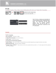
K R A ME R E LE CT R O N IC S L TD . USER MANUAL MODELS: TP-145 XGA/Audio/Data Line Transmitter TP-146 UXGA/Audio/Data Line Receiver P/N: 2900-000607 Rev 3 Contents 1 Introduction 1 2 2.1 2.2 2.3 3 3.1 3.2 3.3 3.4 Getting Started Achieving the Best Performance Safety Instructions Recycling Kramer Products Overview Defining the TP-145 UXGA/Audio/Data Line Transmitter Defining the TP-146 UXGA/Audio/Data Line Receiver Internal Polarity and Sync Mode Switches Shielded Twisted Pair/Unshielded Twisted Pair 2 2 3 3 4 4 6 7 8 4 4.1 4.2 5 Connecting the TP-145, TP-146 Transmitting via RS-232 Wiring the TP LINE IN / LINE OUT RJ-45 Connectors Acquiring the EDID 9 11 12 13 6 Technical Specifications 14 Figures Figure 1: TP-145 UXGA/Audio/Data Line Transmitter Figure 2: TP-145, TP-146 UXGA/Audio/Data Line Transmitter/Receiver Figure 3: TP-146 Internal Polarity Switches Figure 4: Connecting the TP-145, TP-146 UXGA/Audio/Data Line Transmitter/Receiver Figure 5: RS-232 Pinout Connection Figure 6: TP PINOUT 5 6 7 10 11 12 TP-145, TP-146 – Contents i 1 Introduction Welcome to Kramer Electronics! Since 1981, Kramer Electronics has been providing a world of unique, creative, and affordable solutions to the vast range of problems that confront video, audio, presentation, and broadcasting professionals on a daily basis. In recent years, we have redesigned and upgraded most of our line, making the best even better! Our 1,000-plus different models now appear in 11 groups that are clearly defined by function: GROUP 1: Distribution Amplifiers; GROUP 2: Switchers and Routers; GROUP 3: Control Systems; GROUP 4: Format/Standards Converters; GROUP 5: Range Extenders and Repeaters; GROUP 6: Specialty AV Products; GROUP 7: Scan Converters and Scalers; GROUP 8: Cables and Connectors; GROUP 9: Room Connectivity; GROUP 10: Accessories and Rack Adapters and GROUP 11: Sierra Products. Congratulations on purchasing your Kramer TP-145, TP-146 UXGA/Audio/Data Line Transmitter/Receiver, which is ideal for the following typical applications: Presentation and multimedia applications Long-range graphics distribution for schools, hospitals, security, and stores TP-145, TP-146 - Introduction 1 2 Getting Started We recommend that you: Unpack the equipment carefully and save the original box and packaging materials for possible future shipment Review the contents of this user manual i 2.1 Go to http://www.kramerelectronics.com/support/product_downloads.asp to check for up-to-date user manuals, application programs, and to check if firmware upgrades are available (where appropriate). Achieving the Best Performance To achieve the best performance: Use only good quality connection cables (we recommend Kramer highperformance, high-resolution cables) to avoid interference, deterioration in signal quality due to poor matching, and elevated noise levels (often associated with low quality cables) Do not secure the cables in tight bundles or roll the slack into tight coils Avoid interference from neighboring electrical appliances that may adversely influence signal quality Position your Kramer TP-145, TP-146 away from moisture, excessive sunlight and dust ! 2 This equipment is to be used only inside a building. It may only be connected to other equipment that is installed inside a building. TP-145, TP-146 - Getting Started 2.2 Safety Instructions ! 2.3 Caution: There are no operator serviceable parts inside the unit Warning: Use only the Kramer Electronics input power wall adapter that is provided with the unit Warning: Disconnect the power and unplug the unit from the wall before installing Recycling Kramer Products The Waste Electrical and Electronic Equipment (WEEE) Directive 2002/96/EC aims to reduce the amount of WEEE sent for disposal to landfill or incineration by requiring it to be collected and recycled. To comply with the WEEE Directive, Kramer Electronics has made arrangements with the European Advanced Recycling Network (EARN) and will cover any costs of treatment, recycling and recovery of waste Kramer Electronics branded equipment on arrival at the EARN facility. For details of Kramer’s recycling arrangements in your particular country go to our recycling pages at http://www.kramerelectronics.com/support/recycling/. TP-145, TP-146 - Getting Started 3 3 Overview The TP-145 and TP-146 are high-performance, twisted pair (TP) transmitter and receivers for computer graphics video (including HDTV), unbalanced stereo audio, and RS-232 control commands. The TP-145 converts computer graphics video, unbalanced stereo analog audio, and RS-232 control commands to a TP signal. The TP-146 converts the TP signal back into computer graphics video, unbalanced stereo and S/PDIF digital audio, and RS-232 control signals. The TP-145 and TP-146 together form a computer graphics/audio/control data line transmitter/receiver system. More specifically, the products feature: Resolution up to WUXGA 1920 x 1200 HDTV compatibility EDID capture and status indication (TP-145) Simultaneous unbalanced stereo and S/PDIF (24-bit 48kHz) audio outputs (TP-146) Level (gain) and EQ (peaking) controls (TP-146) Full duplex RS-232 transmission Increased level of protection against noise, spikes, and interference in adverse environments 3.1 System range up to 200m (656ft) Defining the TP-145 UXGA/Audio/Data Line Transmitter The TP-145 is a high-performance transmitter that accepts: A computer graphics input signal An unbalanced stereo analog audio signal RS-232 control commands The TP-145 encodes the signals and transmits them over TP cable to a TP-146 receiver. The stereo analog audio signal is converted to a digital audio (S/PDIF) 4 TP-145, TP-146 - Overview stream before transmission, thus preserving the quality of the audio source signals. Commands and data can flow in both directions simultaneously via the RS-232 interface, allowing status requests and control of the destination unit. When the TP-145 is connected to a display device and the EDID CAPTURE button is pressed, the TP-145 reads and stores the EDID (Extended Display Identification Data) from the display device. This prevents the problem whereby a source (for example, a PC), fails to output video because it was not connected to the display device when attempting to read its EDID. Figure 1 defines the TP-145 UXGA/Audio/Data Line Transmitter. Figure 1: TP-145 UXGA/Audio/Data Line Transmitter # Feature 1 EDID CAPTURE Button Press to capture the EDID 2 EDID STATUS LED Lights Green when the EDID has been successfully captured 3 ON LED Lights Green when the unit receives power 4 XGA IN 15-pin HD (F) Connector Connect to the UXGA source 5 LINE OUT RJ-45 Connector Connect to the LINE IN RJ-45 connector on the TP-146 6 RS-232 Terminal Block Connect to the PC or the remote controller (see Section 4.1) 7 AUDIO IN 3.5mm Mini Connector Connect to the analog audio source 8 12V DC Power Connector Connect to the supplied +12V DC power adapter, center conductor positive TP-145, TP-146 - Overview Function 5 3.2 Defining the TP-146 UXGA/Audio/Data Line Receiver The TP-146 is a high-performance receiver that accepts the computer graphics signal/audio/control data from the Kramer TP-145 via TP cabling at its RJ-45 LINE IN input. The TP-146 outputs a computer graphics signal, an unbalanced stereo analog audio signal, a converted digital audio (S/PDIF) signal, and bi-directional RS-232 control commands and data. The RS-232 interface makes it possible to control virtually any device over a transmission range of up to 200m (660ft) with a Kramer TP-141/145 transmitter over TP cabling. In addition, the TP-146 features: Level and equalization control for the UXGA signal The capability to change the polarity of the vertical and horizontal sync signals 24-bit 48kHz S/PDIF digital audio Figure 2 defines the TP-146 UXGA/Audio/Data Line Receiver. Figure 2: TP-145, TP-146 UXGA/Audio/Data Line Transmitter/Receiver # Feature 1 LINK LED Lights green when a link is established Function 2 LEVEL Trimmer Adjusts the output signal level 3 EQ. Trimmer Adjusts the cable compensation equalization level 4 ON LED Lights green when the unit receives power 5 UXGA OUT 15-pin HD (F) Connector Connect to the UXGA acceptor 6 LINE IN RJ-45 Connector Connect to the LINE OUT RJ-45 connector on the TP-145 Using a TP cable with RJ-45 connectors at both ends (pinout is defined in Figure 6) 7 6 RS-232 Terminal Block Connect to the controlled unit TP-145, TP-146 - Overview 3.3 # Feature 8 AUDIO OUT ANALOG 3.5mm Mini Connector Connect to the analog audio acceptor Function 9 AUDIO OUT S/PDIF RCA Connector Connect to the digital audio acceptor 10 12V DC Connector Connect to the supplied +12V DC power adapter. Center pin positive Internal Polarity and Sync Mode Switches Figure 3 defines the internal horizontal and vertical polarity switches of the TP-146. Note: Open the TP-146 unit to gain access to the Hs and Vs polarity and video selection switches which are located on the lower part of the printed circuit board next to the ON LED. After setting the switches, close the TP-146. Figure 3: TP-146 Internal Polarity Switches Switch/Jumper Function SW1 Horizontal Sync Switch Slide up to set the H Sync to positive polarity Slide down to set the H Sync to negative polarity Default = up (positive polarity) SW2 Vertical Sync Switch Slide up to set the V Sync to positive polarity Slide down to set the V Sync to negative polarity Default = up (positive polarity) SW3 Video Selection Switch Slide left to set the video to RGBHV/VGA Slide right to set the video to component/composite video with sync Default = left (RGBHV/VGA video) TP-145, TP-146 - Overview 7 3.4 Shielded Twisted Pair/Unshielded Twisted Pair We recommend that you use Shielded Twisted Pair (STP) cable. There are different categories of STP cable available and we advise you to use the best quality STP cable that you can afford. Our non-skew-free cable, Kramer BC-STP is intended for digital signals and for analog signals where skewing is not an issue. For cases where there is skewing, our Unshielded Twisted Pair (UTP) skew-free cable, Kramer BC-XTP, may be used. Bear in mind though, that we advise using STP cables where possible, since the compliance to electromagnetic interference has been tested using STP cables. Although UTP cable might be preferred for long range applications, the UTP cable should be installed as far as possible from electric cables, motors, and so on, which often create electrical interference. However, since the use of UTP cable might cause non-conformity to electromagnetic standards, Kramer does not commit to meeting the standard with UTP cable. 8 TP-145, TP-146 - Overview 4 Connecting the TP-145, TP-146 i Always switch off the power to each device before connecting it to your TP-145, TP-146. After connecting your TP-145, TP-146, connect its power and then switch on the power to each device. You can use the TP-145 UXGA/Audio/Data Line Transmitter and the TP-146 UXGA/Audio/Data Line Receiver to configure a TP transmitter and receiver system that transmit video, audio, and RS-232 control signals via TP cable. To connect the TP-145 and the TP-146 to create a TP transmitter and receiver system, as illustrated in Figure 4: 1. On the TP-145, connect: A UXGA source (for example, the graphics card on a laptop) to the UXGA IN 15-pin HD (F) connector An audio source to the AUDIO IN 3.5mm mini connector, for example, using a Kramer C-GMA/GMA cable (VGA 15-pin HD (M) +Audio jack to VGA 15-pin HD (M) +Audio jack) Not supplied. The full list of Kramer cables is available from http://www.kramerelectronics.com. Alternatively, you can connect a UXGA source to the UXGA IN 15-pin HD (F) connector, and a separate audio source to the AUDIO IN 3.5mm mini connector An RS-232 cable with a 9-pin D-sub connector at one end to the laptop, and a 3-pin terminal block connector at the other end to the TP-145 RS-232 port (as defined in Section 4.1) 2. On the TP-146, connect: The UXGA OUT 15-pin HD (F) connector to the AV display system The S/PDIF AUDIO OUT RCA connector to a digital AV Receiver An RS-232 cable with a 3 pin terminal block connector at one end to the TP-146 RS-232 port, and a 9-pin D-SUB connector at the other end to the RS-232 port on the AV display system 3. Using STP cabling, connect the LINE OUT RJ-45 connector on the TP-145 to the LINE IN RJ-45 connector on the TP-146. For details of how to wire a TP RJ-45 connector, see Section 4.2 TP-145, TP-146 - Connecting the TP-145, TP-146 9 4. Connect the power adapter to the power socket on the TP-145 and/or TP-146 (if needed), and connect the adapter(s) to the mains electricity. 5. On the TP-146: If necessary, adjust the video output signal level and/or cable compensation equalization level with a flat screwdriver If necessary, set the horizontal sync switches, vertical sync switches, and the sync mode jumpers Figure 4: Connecting the TP-145, TP-146 UXGA/Audio/Data Line Transmitter/Receiver 10 TP-145, TP-146 - Connecting the TP-145, TP-146 4.1 Transmitting via RS-232 It is possible to transmit data (for example, using a PC) between the TP-145 and TP-146 via the RS-232 terminal block. Prepare an RS-232 cable with a 9-pin D-sub connector at one end, and a 3-pin terminal block at the other end as defined in Figure 5. Terminal Block 9-pin D-sub Connector TxD Pin 2 RxD Pin 3 GND Pin 5 Figure 5: RS-232 Pinout Connection TP-145, TP-146 - Connecting the TP-145, TP-146 11 4.2 Wiring the TP LINE IN / LINE OUT RJ-45 Connectors This section defines the TP pinout, using a straight pin-to-pin cable with RJ-45 connectors. i Note, that the cable ground shielding must be connected/soldered to the connector shield. EIA /TIA 568B 12 PIN 1 Wire Color Orange / White 2 Orange 3 Green / White 4 Blue 5 Blue / White 6 Green 7 Brown / White 8 Brown Figure 6: TP PINOUT TP-145, TP-146 - Connecting the TP-145, TP-146 5 Acquiring the EDID The TP-145 transmitter can capture the EDID information from a display device. To load the default EDID: 1. Plug the 12V DC power adapter into the power socket on the TP-145 and connect the adapter to the mains electricity. 2. With no display device connected to the TP-145, press the EDID CAPTURE button. 3. The EDID STATUS LED flashes rapidly several times and the new EDID is copied. To capture the EDID information from a display device: 1. Using a short cable (for example, Kramer model number C-MGM/MGM-1), connect the XGA INPUT 15-pin HD connector on the TP-145 to the input XGA connector of the display. 2. Connect power to the display and switch it on. 3. Plug the 12V DC power adapter into the power socket on the TP-145 and to the mains electricity. 4. Press the EDID CAPTURE button. 5. The EDID STATUS LED flashes slowly several times and the EDID is captured. 6. Disconnect the display. TP-145, TP-146 - Acquiring the EDID 13 6 Technical Specifications TP-145 TP-146 INPUTS: 1 XGA on a 15-pin HD connector, 1 unbalanced stereo audio a 3.5mm mini connector 1 twisted pair on an RJ-45 connector OUTPUTS: 1 twisted pair on an RJ-45 connector 1 UXGA on a 15-pin HD connector, 1 S/PDIF on an RCA connector, 1 unbalanced stereo audio a 3.5mm mini connector PORTS: 1 RS-232 bidirectional terminal block RESOLUTION: Up to WUXGA, 1080p MAX. OUTPUT LEVEL: Video: 1.6V Audio: 2.3V Level: –7.5dB to +4.4dB, EQ.: 0dB to +33dBm (130m) @ 50MHz CONTROLS: EDID capture button RS-232 BAUD RATE: Up to 19200kbps RS-232 MODE: Full-duplex BANDWIDTH: Audio: 20Hz – 20kHz @0.5dB S/N RATIO: Audio: <–80dB TOTAL GAIN: Analog/analog: 0dB Analog/SPDIF: –12dBFS COUPLING: AC TND+N: Audio: <0.01% POWER CONSUMPTION: 12V DC 215mA OPERATING TEMPERATURE: 0° to +40°C (32° to 104°F) STORAGE TEMPERATURE: -40° to +70°C (-40° to 158°F) HUMIDITY: 10% to 90%, RHL non-condensing DIMENSIONS: 12.0cm x 7.8cm x 2.5cm (4.7" x 3.1" x 1.0") W, D, H WEIGHT: 0.18kg. (0.4lbs.) approx. INCLUDED ACCESSORIES: Power supply OPTIONAL: RK-3T 19” rack adapter 12V DC 550mA Specifications are subject to change without notice at http://www.kramerelectronics.com 14 TP-145, TP-146 - Technical Specifications For the latest information on our products and a list of Kramer distributors, visit our Web site where updates to this user manual may be found. We welcome your questions, comments, and feedback. Web site: www.kramerelectronics.com E-mail: [email protected] ! P/N: SAFETY WARNING Disconnect the unit from the power supply before opening and servicing 2900- 000607 Rev: 3