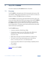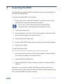
1
K R A ME R E LE CT R O N IC S L T D . USER MANUAL MODELS: TP-121EDID, XGA /Audio Line Transmitter TP-123EDID, XGA /Audio/Data Line Transmitter TP-125EDID, XGA /Audio/Data Line Transmitter PT-110EDID, XGA Line Transmitter P/N: 2900-000585 Rev 6 Contents 1 Introduction 1 2 2.1 2.2 2.3 3 3.1 3.2 Getting Started Achieving the Best Performance Safety Instructions Recycling Kramer Products Overview About Shielded Twisted Pair (STP)/Unshielded Twisted Pair (UTP) About the Power Connect™ Feature 2 2 3 3 4 4 5 4 4.1 4.2 4.3 Your TP-121EDID Overview Connecting the TP-121EDID XGA/Audio Line Transmitter Technical Specifications - TP-121EDID 6 6 7 10 5 5.1 5.2 5.3 5.4 6 6.1 6.2 6.3 6.4 Your TP-123EDID Overview Connecting the TP-123EDID XGA/Audio/Data Line Transmitter Connecting the RS-232 Port Technical Specifications – TP123EDID Your TP-125EDID Overview Connecting the TP-125EDID XGA/Audio/Data Line Transmitter Connecting the RS-232 Port Technical Specifications – TP-125EDID 11 11 12 14 15 16 16 17 19 20 7 7.1 7.2 7.3 Your PT-110EDID Overview Connecting the PT-110EDID XGA/Line Transmitter Technical Specifications PT-110EDID 21 21 22 24 8 Wiring the TP LINE IN/LINE OUT RJ-45 Connectors 25 9 Acquiring the EDID 26 Figures Figure 1: TP-121EDID XGA/Audio Line Transmitter Figure 2: Connecting the TP-121EDID XGA/Audio Line Transmitter Figure 3: TP-123EDID XGA/Audio/Data Line Transmitter Figure 4: Connecting the TP-123EDID XGA/Audio/Data Line Transmitter Figure 5: RS-232 PINOUT Connection Figure 6: TP-125EDID XGA/Audio/Data Line Transmitter Figure 7: Connecting the TP-125EDID XGA/Audio/Data Line Transmitter Figure 8: RS-232 PINOUT Connection Figure 9: PT-110EDID XGA Line Transmitter Figure 10: Connecting the PT-110EDID XGA/Line Transmitter Figure 11: TP PINOUT 7 9 12 14 15 17 19 20 22 23 25 TP-121/3/5EDID, PT-110EDID – Contents i 1 Introduction Welcome to Kramer Electronics! Since 1981, Kramer Electronics has been providing a world of unique, creative, and affordable solutions to the vast range of problems that confront video, audio, presentation, and broadcasting professionals on a daily basis. In recent years, we have redesigned and upgraded most of our line, making the best even better! Our 1,000-plus different models now appear in 11 groups that are clearly defined by function: GROUP 1: Distribution Amplifiers; GROUP 2: Switchers and Routers; GROUP 3: Control Systems; GROUP 4: Format/Standards Converters; GROUP 5: Range Extenders and Repeaters; GROUP 6: Specialty AV Products; GROUP 7: Scan Converters and Scalers; GROUP 8: Cables and Connectors; GROUP 9: Room Connectivity; GROUP 10: Accessories and Rack Adapters and GROUP 11: Sierra Video Products. Thank you for purchasing your Kramer TOOLS: TP-121EDID XGA/Audio Line Transmitter, and/or TP-123EDID, XGA/Audio/Data Line Transmitter, and/or TP-125EDID, XGA/Audio/Data Line Transmitter, and/or Kramer Pico TOOLS™ PT-110EDID, XGA Line Transmitter, which are ideal for: • • Presentation and multimedia applications Long-range graphics distribution for schools, hospitals, security, and stores TP-121/3/5EDID, PT-110EDID - Introduction 1 2 Getting Started We recommend that you: • Unpack the equipment carefully and save the original box and packaging materials for possible future shipment • Review the contents of this user manual • Use Kramer high performance high resolution cables i 2.1 Go to http://www.kramerelectronics.com to check for up-to-date user manuals, application programs, and to check if firmware upgrades are available (where appropriate). Achieving the Best Performance To achieve the best performance: • Use only good quality connection cables to avoid interference, deterioration in signal quality due to poor matching, and elevated noise levels (often associated with low quality cables) • Do not secure the cables in tight bundles or roll the slack into tight coils • Avoid interference from neighboring electrical appliances that may adversely influence signal quality • Position your Kramer products away from moisture, excessive sunlight and dust ! 2 This equipment is to be used only inside a building. It may only be connected to other equipment that is installed inside a building. TP-121/3/5EDID, PT-110EDID - Getting Started 2.2 Safety Instructions ! 2.3 Caution: There are no operator serviceable parts inside the unit Warning: Use only the Kramer Electronics input power wall adapter that is provided with the unit Warning: Disconnect the power and unplug the unit from the wall before installing Recycling Kramer Products The Waste Electrical and Electronic Equipment (WEEE) Directive 2002/96/EC aims to reduce the amount of WEEE sent for disposal to landfill or incineration by requiring it to be collected and recycled. To comply with the WEEE Directive, Kramer Electronics has made arrangements with the European Advanced Recycling Network (EARN) and will cover any costs of treatment, recycling and recovery of waste Kramer Electronics branded equipment on arrival at the EARN facility. For details of Kramer’s recycling arrangements in your particular country go to our recycling pages at http://www.kramerelectronics.com/support/recycling/. TP-121/3/5EDID, PT-110EDID - Getting Started 3 3 Overview This user manual describes the following devices: • TP-121EDID XGA/Audio Line Transmitter (see Section 4) • TP-123EDID XGA/Audio/Data Line Transmitter (see Section 5) • TP-125EDID XGA/Audio/Data Line Transmitter (see Section 6) • PT-110EDID XGA Line Transmitter (see Section 7) This section also describes: • Using shielded twisted pair (STP)/unshielded twisted pair (UTP), see Section 3.1 • 3.1 The power connect feature, see Section 3.2 About Shielded Twisted Pair (STP)/Unshielded Twisted Pair (UTP) We recommend that you use Shielded Twisted Pair (STP) cable, and stress that the compliance to electromagnetic interference was tested using STP cable. There are different levels of STP cable available, and we advise you to use the best quality STP cable that you can afford. Our non-skew-free cable, Kramer BC-STP is intended for analog signals where skewing is not an issue. In cases where there is skewing, our Unshielded Twisted Pair (UTP) skew-free cable, Kramer BC-XTP, may be advantageous, and UTP cable might also be preferable for long-range applications. In any event when using UTP cable, it is advisable to ensure that the cable is installed far away from electric cables, motors and so on, which are prone to create electrical interference. 4 TP-121/3/5EDID, PT-110EDID - Overview 3.2 About the Power Connect™ Feature The Power Connect feature applies as long as the cable can carry power. This feature is available when using STP cable and the distance does not exceed 50m (164ft) on standard CAT 5 cable. For longer distances, heavy-gauge cable should be used (TP cable is still suitable for the video/audio transmission, but not for feeding power at these distances). For units that are connected via RJ-45 connectors, make sure that the shield of the STP cable is connected to the metal casing of the connectors on both ends of the cable. For units that are connected via terminal block connectors, the shield of the STP cable must be connected to a ground terminal on the units at both ends. (Use the ground terminal of the power supply connection if necessary.) For a TP cable exceeding a distance of 50m, separate power supplies should be connected to the transmitter and to the receiver simultaneously. TP-121/3/5EDID, PT-110EDID - Overview 5 4 Your TP-121EDID This section describes the TP-121EDID XGA/Audio Line Receiver. 4.1 Overview The TP-121EDID is a high-performance XGA/stereo audio line transmitter. It inputs an XGA signal (up to WUXGA, 1080p) and an unbalanced stereo audio signal and transmits them over CAT 5 cable to a receiver (for example, the Kramer TP-122N). It converts the unbalanced stereo audio signal to a digital audio (S/PDIF) stream before transmitting, to preserve the quality of the audio signal. When the TP-121EDID is connected to a display device and the EDID CAPTURE button is pressed, the TP-121EDID reads and stores the EDID (Extended Display Identification Data) from the display device. The display can be disconnected and later reconnected without rebooting the operating system. The TP-121EDID features: • A maximum resolution of WUXGA and 1080p • A transmission range of more than 300ft (100m), and a 20kHz audio bandwidth with an S/N ratio that exceeds 80dB on the same transmission range • EDID Capture that copies and stores the EDID from a display device • The Power Connect Feature that transmits power to the receiving device, or receives power from it, over twisted pair cable • 12V DC power Figure 1 defines the TP-121EDID: 6 TP-121/3/5EDID, PT-110EDID - Your TP-121EDID Figure 1: TP-121EDID XGA/Audio Line Transmitter # 1 EDID 2 Feature CAPTURE Button Function Press to capture the EDID information from the display STATUS LED Illuminates during normal operation; flashes when acquiring the EDID 3 ON LED Illuminates when receiving power 4 XGA IN 15-pin HD (F) connector Connects to the XGA source 5 LINE OUT RJ-45 connector Connects to the LINE IN RJ-45 connector on a receiver Using a CAT 5 cable with RJ-45 connectors at both ends (the PINOUT is defined in Section 8) 4.2 6 AUDIO IN 3.5mm mini jack Connects to the audio source 7 12V DC +12V DC connector for powering the unit Connecting the TP-121EDID XGA/Audio Line Transmitter You can use the TP-121EDID together with the TP-122N to configure a twisted pair transmitter and receiver system, to transmit the video and audio signals via CAT 5 cable. i Before connecting the transmitter and receiver system you can acquire the EDID from the display or set the system to the default EDID, see Section 9. TP-121/3/5EDID, PT-110EDID - Your TP-121EDID 7 To connect the TP-121EDID with the TP-122N, as the example in Figure 2 illustrates, do the following: 1. On the TP-121EDID, connect the: XGA source (for example, a laptop’s graphics card) to the XGA IN 15-pin HD (F) connector Audio source (for example, the audio out of the PC) to the AUDIO IN 3.5mm mini jack You can use a Kramer C-GMA/GMA cable (VGA 15-pin HD (M) + audio jack to VGA 15-pin HD (M) + audio jack) to make both connections on one cable. Cables are not supplied. The complete list of Kramer cables is on our Web site at http://www.kramerelectronics.com. 2. On the TP-122N, connect the: XGA OUT 15-pin HD (F) connector to the XGA acceptor (for example, a display) AUDIO OUT S/PDIF RCA connector to the digital audio acceptor (for example, an AV receiver) ANALOG 3.5mm mini jack to the analog audio acceptor (for example, a stereo audio recorder) 3. Connect the LINE OUT RJ-45 connector on the TP-121EDID to the LINE IN RJ-45 connector on the TP-122N, using CAT 5 cabling. CAT 5 cable has a range of greater than 300ft (>100m). For details of how to wire a CAT 5 LINE IN/LINE OUT RJ-45 connector, see Section 8. 4. Connect the 12V DC power adapter to the power socket and connect the adapter to the mains electricity on both the TP-121EDID and the TP-122N. If you cannot connect the power to both the TP-121EDID and TP-122N, connect the power only to any one unit. 5. On the TP-122N: Adjust the video output signal level and/or cable compensation equalization level, if required Use a screwdriver to carefully rotate the trimmer, adjusting the appropriate level. If necessary, set the H SYNC and V SYNC switches, on the underside By default, both switches are set down (for negative V SYNC and H SYNC polarity). 8 TP-121/3/5EDID, PT-110EDID - Your TP-121EDID Figure 2: Connecting the TP-121EDID XGA/Audio Line Transmitter TP-121/3/5EDID, PT-110EDID - Your TP-121EDID 9 4.3 Technical Specifications - TP-121EDID INPUTS: Video: 1 VGA/UXGA on a 15-pin HD connector Audio: 1 audio ANALOG 3.5mm mini jack OUTPUT: 1 RJ-45 OUT connector BANDWIDTH (-3dB): Audio: 20Hz to 20kHz @0.5dB RESOLUTION: Up to WUXGA and 1080p S/N RATIO: Video: 58dB unweighted, 68.3dB @5MHz weighted Audio: <-80dB TOTAL GAIN: Audio: Analog/analog: 0dB; Analog/SPDIF: –12dBFS COUPLING: AC TND+N: Audio: <0.01% POWER CONSUMPTION: 12V DC, 540mA OPERATING TEMPERATURE: 0° to +40°C (32° to 104°F) STORAGE TEMPERATURE: -40° to +70°C (-40° to 158°F) HUMIDITY: 10% to 90%, RHL non-condensing DIMENSIONS: 12.1cm x 7.18cm x 2.42cm (4.76" x 2.83" x 0.95") W, D, H WEIGHT: 0.3kg (0.67lbs) approx. ACCESSORIES: Power supply OPTIONS: RK-3T 19” rack adapter All measurements are based on the transmitter/receiver pair. Specifications are subject to change without notice at http://www.kramerelectronics.com 10 TP-121/3/5EDID, PT-110EDID - Your TP-121EDID 5 Your TP-123EDID This section describes the TP-123EDID XGA/Audio/Data Line Transmitter. 5.1 Overview The TP-123EDID is a high-performance XGA/stereo audio line transmitter. It inputs an XGA signal (up to WUXGA, 1080p), unbalanced stereo audio signal, and unidirectional (RxD) RS-232 control commands and transmits them over CAT 5 cable to a receiver (for example, the Kramer TP-124 XGA/Audio/Data Line Receiver). It converts the unbalanced stereo audio signal to a digital audio (S/PDIF) stream before transmitting, to preserve the quality of the audio signal. When the TP-123EDID is connected to a display device and the EDID CAPTURE button is pressed, the TP-123EDID reads and stores the EDID (Extended Display Identification Data) from the display device. The display can be disconnected and later reconnected without rebooting the operating system. The TP-123EDID features: • A maximum resolution of WUXGA and 1080p • A transmission range of more than 300ft (100m), and a 20kHz audio bandwidth with an S/N ratio that exceeds 80dB on the same transmission range • A unidirectional RS-232 port for transmitting control commands • EDID Capture that copies and stores the EDID from a display device • The Power Connect Feature that transmits power to the receiving device, or receives power from it, over twisted pair cable • 12V DC power Figure 3 defines the TP-123EDID: TP-121/3/5EDID, PT-110EDID - Your TP-123EDID 11 Figure 3: TP-123EDID XGA/Audio/Data Line Transmitter # 1 EDID 2 Feature CAPTURE Button Function Press to acquire the EDID information from the display STATUS LED Illuminates during normal operation; flashes when acquiring the EDID 3 ON LED Illuminates when receiving power 4 XGA IN 15-pin HD (F) connector Connect to the XGA source 5 LINE OUT RJ-45 connector Connects to the LINE IN RJ-45 connector on the TP-124 XGA/Audio Line Receiver Use a CAT 5 cable with RJ-45 connectors at both ends (the PINOUT is defined in Section 8) 5.2 6 RS-232 terminal block connector Connects to the PC or the Remote Controller (see Section 5.3) 7 AUDIO IN 3.5mm mini jack Connects to the audio source 8 12V DC +12V DC connector for powering the unit Connecting the TP-123EDID XGA/Audio/Data Line Transmitter You can use the TP-123EDID together with the TP-124 XGA/Audio/Data Line Receiver to configure a twisted pair transmitter and receiver system, to transmit the video, audio and RS-232 control signals via CAT 5 cable. i 12 Before connecting the transmitter and receiver system you can acquire the EDID from the display or set the system to the default EDID, see Section 9. TP-121/3/5EDID, PT-110EDID - Your TP-123EDID To connect the TP-123EDID and the TP-124, as the example in Figure 4 illustrates, do the following: 1. On the TP-123EDID, connect the: XGA source (for example, a laptop’s graphics card) to the XGA IN 15-pin HD (F) connector Audio source (for example, the audio out of the PC) to the AUDIO IN 3.5mm mini jack You can use a Kramer C-GMA/GMA cable (VGA 15-pin HD (M) + audio jack to VGA 15-pin HD (M) + audio jack) to make both connections on one cable. Cables are not supplied. The complete list of Kramer cables is on our Web site at http://www.kramerelectronics.com. RS-232 cable with a 9-pin D-sub connector to the laptop, and a 2-pin terminal block connector to the TP-123EDID RS-232 port (as shown in Figure 5). 2. On the TP-124, connect: The XGA OUT 15-pin HD (F) connector to a display The S/PDIF audio OUT RCA connector to a digital AV receiver (leave the ANALOG audio OUT 3.5mm mini jack unconnected) An RS-232 cable with a 2-pin terminal block connector to the TP-124 RS-232 port, and a 9-pin D-sub connector to the RS-232 port on an RS-232 controllable device (for example, a switcher) 3. Connect the Line OUT RJ-45 connector on the TP-123EDID to the LINE IN RJ-45 connector on the TP-124, via CAT 5 cabling. CAT 5 cable has a range of greater than 300ft (>100m). For details of how to wire a CAT 5 LINE IN/LINE OUT RJ-45 connector, see Section 8. 4. Connect the 12V DC power adapter to the power socket and connect the adapter to the mains electricity on both the TP-123EDID and the TP-124. If you cannot connect the power to both the TP-123EDID and TP-124, connect the power to any one unit. 5. On the TP-124: Adjust the video output signal level and/or cable compensation equalization level, if required Use a screwdriver to carefully rotate the trimmer, adjusting the appropriate level. TP-121/3/5EDID, PT-110EDID - Your TP-123EDID 13 If necessary, set the H SYNC and V SYNC switches, on the underside By default, both switches are set down (for negative V SYNC and H SYNC polarity). Figure 4: Connecting the TP-123EDID XGA/Audio/Data Line Transmitter 5.3 Connecting the RS-232 Port To control an RS-232 controllable remote device from a PC or RS-232 controller, prepare an RS-232 cable with a 9-pin D-sub connector at one end, and a 2-pin terminal block connector at the other end, as shown in Figure 5. 14 TP-121/3/5EDID, PT-110EDID - Your TP-123EDID Figure 5: RS-232 PINOUT Connection 5.4 Connect this PIN on the Terminal Block Connector: TxD To this PIN on the 9-pin D-sub Connector PIN 2 RxD PIN 3 GND PIN 5 Technical Specifications – TP123EDID INPUTS: Video: 1 VGA/UXGA on a 15-pin HD connector Audio: 1 audio ANALOG 3.5mm mini jack OUTPUT: 1 RJ-45 OUT connector CONTROL: RS-232 2-pin terminal block RS-232 BAUD RATE: Up to 19200kbps BANDWIDTH (-3dB): Audio: 20Hz to 20kHz @0.5dB RESOLUTION: Up to WUXGA and 1080p S/N RATIO: Video: 58dB unweighted, 68.3dB @5MHz weighted Audio: <-80dB TOTAL GAIN: Audio: Analog/analog: 0dB; Analog/SPDIF: –12dBFS COUPLING: AC TND+N: Audio: <0.01% POWER CONSUMPTION: 12V DC, 550mA OPERATING TEMPERATURE: 0° to +40°C (32° to 104°F) STORAGE TEMPERATURE: -40° to +70°C (-40° to 158°F) HUMIDITY: 10% to 90%, RHL non-condensing DIMENSIONS: 12.1cm x 7.18cm x 2.42cm (4.76" x 2.83" x 0.95") W, D, H WEIGHT: 0.3kg (0.67lbs) approx. ACCESSORIES: Power supply OPTIONS: RK-3T 19” rack adapter All measurements are based on the transmitter/receiver pair. Specifications are subject to change without notice at http://www.kramerelectronics.com TP-121/3/5EDID, PT-110EDID - Your TP-123EDID 15 6 Your TP-125EDID This section describes the TP-125EDID XGA/Audio/Data Line Transmitter. 6.1 Overview The TP-125EDID is a high-performance XGA/stereo audio line transmitter. It inputs an XGA signal (up to WUXGA, 1080p), unbalanced stereo audio signal, and bidirectional RS-232 control commands and transmits them over CAT 5 cable to a receiver (for example, the Kramer TP-126 UXGA/Audio/Data Line Receiver). It converts the unbalanced stereo audio signal to a digital audio (S/PDIF) stream before transmitting, to preserve the quality of the audio signal. Commands and data can flow in both directions via the RS-232 interface, allowing status requests and control of the destination unit. The TP-125EDID includes H and V Sync internal polarity switches. When the TP-125EDID is connected to a display device and the EDID CAPTURE button is pressed, the TP-125EDID reads and stores the EDID (Extended Display Identification Data) from the display device. The display can be disconnected and later reconnected without rebooting the operating system. The TP-125EDID features: • A maximum resolution of WUXGA and 1080p • A transmission range of more than 300ft (100m), and a 20kHz audio bandwidth with an S/N ratio that exceeds 80dB on the same transmission range • A bidirectional RS-232 port where commands and data can flow in both directions via the RS−232 interface, allowing status requests and control of the destination unit 16 • EDID Capture that copies and stores the EDID from a display device • 12V DC power TP-121/3/5EDID, PT-110EDID - Your TP-125EDID Figure 6 defines the TP-125EDID: Figure 6: TP-125EDID XGA/Audio/Data Line Transmitter # 1 EDID 2 Feature CAPTURE Button Function Press to acquire the EDID information from the display STATUS LED Illuminates during normal operation; flashes when acquiring the EDID 3 ON LED Illuminates when receiving power 4 XGA IN 15-pin HD (F) connector Connect to the XGA source 5 LINE OUT RJ-45 connector Connects to the LINE IN RJ-45 connector on the TP-126 XGA/Audio Line Receiver Use a CAT 5 cable with RJ-45 connectors at both ends (the PINOUT is defined in Section 8) 6.2 6 RS-232 terminal block connector Connects to the PC or the Remote Controller (see Section 5.3) 7 AUDIO IN 3.5mm mini jack Connects to the audio source 8 12V DC +12V DC connector for powering the unit Connecting the TP-125EDID XGA/Audio/Data Line Transmitter You can use the TP-125EDID together with the TP-126 UXGA/Audio/Data Line Receiver to configure a twisted pair transmitter and receiver system, to transmit the video, audio and RS-232 control signals via CAT 5 cable. i Before connecting the transmitter and receiver system you can acquire the EDID from the display or set the system to the default EDID, see Section 9. TP-121/3/5EDID, PT-110EDID - Your TP-125EDID 17 To connect the TP-125EDID and the TP-126, as the example in Figure 7 illustrates, do the following: 1. On the TP-125EDID, connect the: XGA source (for example, a laptop’s graphics card) to the XGA IN 15-pin HD (F) connector Audio source (for example, the audio out of the PC) to the AUDIO IN 3.5mm mini jack You can use a Kramer C-GMA/GMA cable (VGA 15-pin HD (M) + audio jack to VGA 15-pin HD (M) + audio jack) to make both connections on one cable. Cables are not supplied. The complete list of Kramer cables is on our Web site at http://www.kramerelectronics.com. An RS-232 cable with a 9-pin D-sub connector to the laptop, and a 3-pin terminal block connector to the TP-125EDID RS-232 port (as shown in Figure 5) 2. On the TP-126, connect: The UXGA OUT 15-pin HD (F) connector to the AV display system The S/PDIF audio OUT RCA connector to a digital AV receiver (leave the ANALOG Audio OUT 3.5mm mini jack unconnected) An RS-232 cable with a 3-pin terminal block connector to the TP-126 RS-232 port, and a 9-PIN D-SUB connector to the RS-232 port on the AV display system 3. Connect the Line OUT RJ-45 connector on the TP-125EDID to the LINE IN RJ-45 connector on the TP-126, via CAT 5 cabling. CAT 5 cable has a range of greater than 300ft (>100m). For details of how to wire a CAT 5 LINE IN/LINE OUT RJ-45 connector, see Section 8. 4. Connect the 12V DC power supply to the power socket and connect the adapter to the mains electricity on both the TP-125EDID and the TP-126. 5. On the TP-126: Adjust the video output signal level and/or cable compensation equalization level, if required Use a screwdriver to carefully rotate the trimmer, adjusting the appropriate level. If necessary, set the H SYNC and V SYNC switches, on the underside By default, both switches are set down (for negative V SYNC and H SYNC polarity). 18 TP-121/3/5EDID, PT-110EDID - Your TP-125EDID Figure 7: Connecting the TP-125EDID XGA/Audio/Data Line Transmitter 6.3 Connecting the RS-232 Port To control an RS-232 controllable remote device from a PC or RS-232 controller, prepare an RS-232 cable with a 9-pin D-sub connector at one end, and a 3-pin terminal block connector at the other end, as shown in Figure 8: TP-121/3/5EDID, PT-110EDID - Your TP-125EDID 19 RS-232 Pinout Connect this PIN on the Terminal Block Connector: TxD PIN 5 Connected to GND PIN 3 Connected to RxD PIN 2 Connected to TxD To this PIN on the 9-pin D-sub Connector PIN 2 RxD PIN 3 GND PIN 5 9 8 7 6 5 GND 4 3 2 1 RxD TxD To PC ( 9-pin D-sub) Figure 8: RS-232 PINOUT Connection 6.4 Technical Specifications – TP-125EDID INPUTS: Video: 1 UXGA on an 15-pin HD connector Audio: 1 audio ANALOG 3.5mm mini jack OUTPUT: 1 RJ-45 OUT connector RESOLUTION: Up to WUXGA and 1080p S/N RATIO: Video: 58dB unweighted, 68.3dB @5MHz weighted Audio: <-80dB CONTROL: RS-232 3-pin terminal block RS-232 BAUD RATE: Up to 19200kbps RS-232 MODE: Full-duplex BANDWIDTH: Audio: 20Hz to 20kHz @0.5dB TOTAL GAIN: Analog/analog: 0dB, analog/SPDIF: -12dBFS COUPLING: AC TND+N: Audio: <0.01% POWER CONSUMPTION: 12V DC 140mA OPERATING TEMPERATURE: 0° to +40°C (32° to 104°F) STORAGE TEMPERATURE: -40° to +70°C (-40° to 158°F) HUMIDITY: 10% to 90%, RHL non-condensing DIMENSIONS: 12.1cm x 7.18cm x 2.42cm (4.76" x 2.83" x 0.95") W, D, H WEIGHT: 0.3kg. (0.67lbs.) approx. ACCESSORIES: Power supply OPTIONS: RK-3T 19” rack adapter All measurements are based on the transmitter/receiver pair, tested with 100m CAT 5 cable. Specifications are subject to change without notice at http://www.kramerelectronics.com 20 TP-121/3/5EDID, PT-110EDID - Your TP-125EDID 7 Your PT-110EDID This section describes the PT-110EDID XGA/Line Transmitter. 7.1 Overview The PT-110EDID is a high-performance XGA line transmitter that inputs an XGA (up to WUXGA, 1080p) signal and transmits it over CAT 5 cable to a receiver (for example, the Kramer TP-122N XGA/Audio Line Receiver). The PT-110EDID is pre-programmed with default EDID information ready for the source even before capturing the EDID from the display. When the PT-110EDID is connected to a display device and the EDID CAPTURE button is pressed, the PT-110EDID reads and stores the EDID (Extended Display Identification Data) from the display device. The display can be disconnected and later reconnected without rebooting the operating system. The PT-110EDID features: • A maximum resolution of WUXGA and 1080p • A transmission range of more than 300ft (100m), and a 20kHz audio bandwidth with an S/N ratio that exceeds 80dB on the same transmission range • EDID Capture that copies and stores the EDID from a display device • The Power Connect Feature that transmits power to the receiving device, or receives power from it, over twisted pair cable • H and V Sync polarity switches for improved display compatibility with the CAT 5 outputs • Is 12V DC fed Figure 9 defines the PT-110EDID: TP-121/3/5EDID, PT-110EDID - Your PT-110EDID 21 Figure 9: PT-110EDID XGA Line Transmitter # 1 Feature XGA IN 15-pin HD (F) Connector Function Connect to the UXGA source 2 12V DC +12V DC connector for powering the unit 3 EDID CAPTURE Button Press to acquire the EDID information from the display (see Section 9) 4 STATUS LED Illuminates during normal operation; flashes when acquiring the EDID 5 LINE OUT RJ-45 Connector Connects to the LINE IN RJ-45 connector on the TP-120 UXGA/Audio Line Receiver 6 VS Switch Slide up to set the V SYNC to NEGATIVE polarity; slide down to set the V SYNC to NORMAL polarity By default, both switches are set down (for normal V SYNC and H SYNC polarity) 7 HS Switch Slide up to set the H SYNC to NEGATIVE polarity (NEG); slide down to set the H SYNC to NORMAL polarity By default, both switches are set down (for normal V SYNC and H SYNC polarity) 8 7.2 ON LED Illuminates when receiving power Connecting the PT-110EDID XGA/Line Transmitter You can use the PT-110EDID XGA Line Transmitter together with the TP-120 XGA Line Receiver to configure an XGA-to-Twisted Pair transmitter and receiver system. i Before connecting the transmitter and receiver system you can acquire the EDID from the display or set the system to the default EDID, see Section 9. To connect the PT-110EDID with the TP-120, as the example in Figure 10 illustrates, do the following: 1. On the PT-110EDID, connect the XGA source (for example, the 15-pin HD output from a computer’s graphics card) to the XGA INPUT 15-pin HD (F) connector. 2. On the TP-120, connect the XGA OUT 15-pin HD (F) connector to the XGA acceptor (for example, a monitor). 22 TP-121/3/5EDID, PT-110EDID - Your PT-110EDID 3. Connect the LINE OUT RJ-45 connector on the PT-110EDID to the LINE IN RJ-45 connector on the TP-120, via CAT 5 cabling. CAT 5 cable has a range of greater than 300ft (>100m). For details of how to wire a CAT 5 LINE IN/LINE OUT RJ-45 connector, see Section 8. 4. On both the PT-110EDID and the TP-120, connect the 12V DC power adapter to the power socket and connect the adapter to the mains electricity. For distances of up to 100 meters you can connect a power adapter to either the PT-110 or TP-120. Above it, both sides should be fed with power 5. On the TP-120, adjust the output signal level and/or cable compensation equalization level, if required. Use a screwdriver to carefully rotate the trimmer, adjusting the appropriate level. 6. If necessary, set the H SYNC and V SYNC switches, on the units. By default, both switches are set for normal H SYNC and V SYNC polarity. Figure 10: Connecting the PT-110EDID XGA/Line Transmitter TP-121/3/5EDID, PT-110EDID - Your PT-110EDID 23 7.3 Technical Specifications PT-110EDID INPUT: 1 VGA/UXGA on a 15-pin HD connector OUTPUT: 1 RJ-45 LINE OUTPUT connector RESOLUTION: Up to WUXGA & 1080p S/N RATIO: 69dB (worst case) COUPLING: AC POWER CONSUMPTION: 12V DC, 320mA OPERATING TEMPERATURE: 0° to +40°C (32° to 104°F) STORAGE TEMPERATURE: -40° to +70°C (-40° to 158°F) HUMIDITY: 10% to 90%, RHL non-condensing DIMENSIONS: 6cm x 6.5cm x 2.5cm, (2.36" x 2.56" x 1") W, D, H WEIGHT: 0.14kg (0.31lbs) approx. ACCESSORIES: Power supply OPTIONS: RK-4PT 19” rack adapters All measurements are based on the transmitter/receiver pair, tested with 100m CAT 5 cable. Specifications are subject to change without notice at http://www.kramerelectronics.com 24 TP-121/3/5EDID, PT-110EDID - Your PT-110EDID 8 Wiring the TP LINE IN/LINE OUT RJ-45 Connectors This section defines the TP pinout, using a straight pin-to-pin cable with RJ-45 connectors. i Note, that the cable Ground shielding must be connected / soldered to the connector shield. EIA /TIA 568B PIN 1 Wire Color Orange / White 2 Orange 3 Green / White 4 Blue 5 Blue / White 6 Green 7 Brown / White 8 Brown Figure 11: TP PINOUT TP-121/3/5EDID, PT-110EDID - Wiring the TP LINE IN/LINE OUT RJ-45 Connectors 25 9 Acquiring the EDID The transmitter can acquire the EDID information from the connected display or it can acquire the default EDID. To acquire the display EDID, do the following: 1. Using a short cable, connect the XGA INPUT 15-pin HD connector of the transmitter to the XGA input connector of the display. i Pins 12 and 15 of the VGA connector carry the EDID signal. The cable used for capturing the EDID must pass all 15 pins. 2. Connect the display power. 3. On the transmitter, connect the 12V DC power adapter to the power socket and connect the adapter to the mains electricity. 4. Press the EDID CAPTURE button. 5. Once the EDID STATUS flashes slowly several times, the EDID is captured. 6. Disconnect the display. To acquire the default EDID: Do not connect the transmitter to the display when acquiring the default EDID. 1. On the transmitter, connect the 12V DC power adapter to the power socket and connect the adapter to the mains electricity. 2. Press the EDID CAPTURE button. 3. Once the EDID STATUS flashes rapidly several times, the default EDID is captured. Alternatively, you can press the EDID CAPTURE button after connecting the transmitter-receiver system. When the EDID STATUS LED flashes rapidly several times, the default EDID information is acquired. 26 TP-121/3/5EDID, PT-110EDID - Acquiring the EDID For the latest information on our products and a list of Kramer distributors, visit our Web site where updates to this user manual may be found. We welcome your questions, comments, and feedback. Web site: www.kramerelectronics.com E-mail: [email protected] ! PN: SAFETY WARNING Disconnect the unit from the power supply before opening and servicing 2900- 000585 Rev: 6