1
MODEL RL1600
AUTOMATED TELLER MACHINE
USER MANUAL
TDN 07103-00190 Aug 7 2009
CORPORATE HEADQUARTERS
21405 B Street
Long Beach, MS 39560
Phone: (228) 575-3188
Fax: (228) 575-3200
COPYRIGHT NOTICE
© 2008 Triton. All Rights Reserved. TRITON logo is a
registered trademark of Triton Systems of Delaware.
MODEL RL1600 USER MANUAL
DOCUMENT UPDATES
Jan 19 2009
Original
Mar 12 2009 Editing updates
May 26 2009 Photograph editing updates to Section 1,2,4,Sup A and B
Aug 7 2009 T5 keypad added as option
ii
MODEL RL1600 USER MANUAL
NOTICES
Copyright © Delaware Capital Formation, Inc., 2007-2008.
ALL RIGHTS RESERVED
This publication is protected by copyright and all rights are reserved. No part of it may be reproduced
or transmitted by any means or in any form, without prior consent in writing from Triton Systems of
Delaware, Inc.
The information in this publication has been carefully checked and is believed to be accurate. However,
Triton Systems of Delaware, Inc. assumes no responsibility for any inaccuracies, errors, or omissions
that may be contained in this document. In no event will Triton Systems of Delaware, Inc. be liable for
direct, indirect, special, incidental, or consequential damages resulting from any defect or omission in
this manual, even if advised of the possibility of such damages.
In the interest of continued product development, Triton Systems of Delaware, Inc. reserves the right
to make improvements in its documentation and the products it describes at any time, without notice or
obligation.
TRADEMARK ACKNOWLEDGEMENTS
Microsoft Windows is a registered trademark of Microsoft Corporation in the United States and/or other
countries. Triton Connect is a trademark of Triton Systems of Delaware, Inc. VISA® is a registered
trademark of VISA of the United States and other countries.
iii
MODEL RL1600 USER MANUAL
CONTENTS
SECTION 1 - INTRODUCTION .........................................................................................1
WHAT’S IN THIS MANUAL....................................................................................................2
FEATURE HIGHLIGHTS / CHANGES............................................................................................................. 3-4
STANDARD FEATURES .............................................................................................................................. 4-5
SECTION 2 - BASIC OPERATION ....................................................................................7
INTRODUCTION ........................................................................................................................................8
CONTROL PANEL LAYOUT ........................................................................................................................8
FUNCTION KEYPADS ................................................................................................................................9
MAIN KEYPAD ........................................................................................................................................ 9
ON-SCREEN KEYPAD OPERATION.............................................................................................................. 10
MENU-BASED OPERATION ........................................................................................................................11
CUSTOMER TRANSACTIONS.......................................................................................................................12
VOICE-ENABLED TRANSACTIONS .............................................................................................................. 14
SECTION 3 - CASSETTE CLOSE / CASH REPLENISHMENT ...............................................15
INTRODUCTION ........................................................................................................................................16
DISPENSING MECHANISMS........................................................................................................................ 16
NOTE CONDITION ....................................................................................................................................17
PREPARING NOTES ...................................................................................................................................17
CASSETTE CLOSE PROCEDURES ..............................................................................................................18
REPLENISH CASSETTE(S)..........................................................................................................19
MINIMECH ............................................................................................................................................. 19-20
SECTION 4 - GENERAL MAINTENANCE..........................................................................21
INTRODUCTION ........................................................................................................................................22
REPLENISHING THE RECEIPT PAPER ........................................................................................................... 22-24
CLEANING THE ENCLOSURE ...................................................................................................................... 25
CLEANING THE DISPLAY...........................................................................................................................25
CARD READER CLEANING ........................................................................................................................25
iv
MODEL RL1600 USER MANUAL
CONTENTS
APPENDIX A - SOFTWARE LICENSE AGREEMENT ..........................................................A-1
APPENDIX B - WARRANTY STATEMENT ........................................................................B-1
APPENDIX C - ELECTRONIC LOCKS ..............................................................................C-1
APPENDIX D - MECHANICAL LOCKS.............................................................................D-1
SUPPLEMENT A - T7 T5 EPP BATTERY REPLACEMENT PROCEDURES.........................SA-1
SUPPLEMENT B - KEY MANAGEMENT.........................................................................SB-1
v
SECTION 1
INTRODUCTION
1
MODEL RL1600 USER MANUAL
WHAT’S IN THIS MANUAL
The User manual describes the operating features of the Model RL1600 series ATM and shows how to
perform the procedures that would typically be performed by the owner or operator personnel.
The manual is divided into the following sections:
SECTION 1, INTRODUCTION. Summarizes the basic features of the Model RL1600 series ATM.
SECTION 2, BASIC OPERATION. Describes the basic operation of the terminal:
¾
¾
¾
¾
¾
Control Panel Layout.
Keypads (Function, Main, On-Screen)
Menu-Based Operation
Customer Transaction Process
Voice-Enabled Transactions
SECTION 3, CASSETTE CLOSE / CASH REPLENISHMENT. Describes the menu functions for cassette close
procedures. Cash replenishment steps for each dispenser and standards are covered as well.
SECTION 4, GENERAL MAINTENANCE. Describes normal preventative and corrective maintenance procedures appropriate for user personnel.
¾
¾
Replenishing Receipt Paper
Cleaning the Enclosure/Card Reader
APPENDIX A - SOFTWARE LICENSE AGREEMENT / COMPLIANCE STATEMENTS
APPENDIX B - WARRANTY STATEMENT
APPENDIX C - ELECTRONIC COMBINATION LOCKS
APPENDIX D - MECHANICAL COMBINATION LOCKS
SUPPLEMENT A -T7 T5 BATTERY REPLACEMENT PROCEDURES
IMPORTANT: Follow the instructions provided in SUPPLEMENT A of this manual for
replacing the battery for the T7 & T5 PCI-EPP. Failure to follow the explicit instructions will
permanently damage the keypad!
SUPPLEMENT B - T7 T5 KEY MANAGEMENT FUNCTIONS.
2
INTRODUCTION
FEATURE HIGHLIGHTS
Important features of the RL1600 series ATM are highlighted in the following list:
Highly reliable, state-of-the-art operating system PC platform design. The RL1600 uses Microsoft®
!
"
#
#
adding custom logos and advertisements. In addition, it features Triton’s completely custom design
X2 motherboard with integrated modem.
Modular architecture eases troubleshooting and servicing.
Front-access unit accommodates single cassette (MiniMech,)
- Only one cabinet design, shallow, accommodates the dispenser mechanism offered.
- Cabinet available in UL 291 Business Hours only. Cash must be removed after hours.
5.7” (145mm) color LCD display.
T7 & T5 PCI-compliant EPP to comply with international encryption standards and Triple DES
compliant.
3
MODEL RL1600 USER MANUAL
FEATURE HIGHLIGHTS
'
#
;
*
"!
by software.
Supports communication types TCP/IP (standard), dial-up (56K baud Triton USB modem - integrated
on motherboard): VSAT (satellite), Radio Pad, and wireless optional.
(Note: For wireless option, please contact your account representative for more information).
Multi-function, dip-style card reader supports magnetic stripe cards or “smart” cards that conform
to the EMV standard. (215 Standard DIP [US] or IS65 EMV DIP [Canada ONLY])
Graphics-capable 60 mm gravity-fed thermal printer designed for quiet operation. Prints receipts,
coupons, and management reports.
%
'*
+
;
'<
"
*
!
!<
"!<
=
Triton Connect™ ATM monitoring software.
Dispenses U.S. and international currency types.
High-capacity electronic journal stores transaction details for later printout and analysis.
"
Americans with Disabilities Act ($>$*
"
#
?
!
for the visually impaired. Complies with UK accessibility guidelines (DDA) and California access
compliance, Title 24.
LED-backlit signage standard (Mid topper attachment).
Bayou Bronze control panel and fascia color.
STANDARD FEATURES
MANAGEMENT FUNCTIONS. Enable extensive control and customization of the ATM’s operating
parameters. See “X-SCALE/X2 CONFIGURATION MANUAL” on web site.
PASSWORD PROTECTION. Access to Management Functions and Key Management areas are protected
with passwords.
MAC ENCRYPTION SUPPORT. Message Authentication Code (MAC) data encryption protocol. Provides
#
#"
#
$%
Triple DES compliant.
PCI-COMPLIANT ENCRYPTING PIN PAD (EPP) ENTRY DEVICE SUPPORT. Secure EPP device encrypts
the customer PIN during a transaction. Triple DES and PCI compliant.
MULTI-LANGUAGE SUPPORT. Enables the customer to select a preferred language (such as French or
Spanish) for customer screens and receipts.
4
INTRODUCTION
TRANSACTION AND ACCOUNT TYPE CONFIGURATION. Enables selection of transactions (transfers or
balance inquiries) or accounts (savings or credit card) that will be presented to the customer. Does
not affect availability of checking account withdrawal.
CASSETTE AND DAY CLOSE REPORTS. Provide summary information about the number and type of
transactions being performed by the ATM.
ELECTRONIC JOURNAL. Stores the details of each transaction in solid-state memory. Journal data can
be retrieved, printed, saved to an external storage device, or transferred to a remote Triton Connect™
computer.
AD SCREENS. An Ad screen is a promotional or advertising graphic that is displayed on the LCD screen
during idle periods. Ad screens are downloaded to the terminal by either using an external storage
device (jumpdrive) or a remote Triton Connect™ computer. Text-only (non-graphic) ad screens can
also be displayed.
RECEIPT PRINTER GRAPHICS. This feature allows informational or promotional graphics to be printed
on customer receipts. Graphics can be loaded from an external storage device or Triton Connect™.
MESSAGES. Informational and promotional messages that are displayed to the customer on-screen or
printed on receipts.
COUPONS. Coupons can be printed by the receipt printer. Prizes may be awarded to customers based
on random and/or withdrawal amount-based transactions. Coupon text can be entered locally or
downloaded along with coupon graphics using Triton Connect™ software.
STATUS MONITORING. The ATM can periodically transfer status information to the host processor.
In addition, Triton Connect™ remote monitoring software can be used to view the journal, monitor
operation and alarm conditions, update operating parameters, and reset the terminal.
UL 291 BUSINESS HOURS SERVICE. Business hours cabinet means currency should be removed from
the dispenser and stored in a safe location when the business is closed to the public.
FRONT-ACCESS CABINET. Allows access to the dispensing mechanism and currency cassette from the
control-panel side of the unit.
Weight of the RL1600
(Approximate)
Business
Hours
140 lbs
63 Kilos
"!
Shallow cab
MiniMech
mid topper
5
MODEL RL1600 USER MANUAL
THIS PAGE INTENTIONALLY LEFT BLANK
6
SECTION 2
BASIC OPERATION
7
MODEL RL1600 USER MANUAL
INTRODUCTION
This section describes the basic operation of the terminal. The following topics are covered:
1.
CONTROL PANEL LAYOUT. Describes the layout of the terminal’s control panel.
2.
KEYPAD OPERATION. Describes the use of the alphanumeric keypads.
3.
MENU-BASED OPERATION. Gives a general overview of the terminal display interface.
4.
CUSTOMER TRANSACTIONS. Summarizes the actions involved in typical customer transactions. In
addition, the voice-enabled transactions feature is described.
CONTROL PANEL LAYOUT
The user interface of the terminal consists of the LCD screen, receipt chute, card reader, speaker, headphone
jack (visually impaired), and 24 keys on three keypads. The Function keys are arranged in two four-key
groups, one group on either side of the LCD display. The main keypad consists of 10 alphanumeric keys,
two arrow keys and four large control keys, all located in a 16-key group beneath the LCD screen.
The main keypad and control keys have an integral raised Braille symbol to conform to the requirements
of the Americans with Disabilities Act (Figure 2-1).
LCD screen
Function
keys
Card
Reader
Receipt
chute
Main
Keypad
Figure 2-1. Control panel layout.
8
BASIC OPERATION
FUNCTION KEYS
The eight (8) keys, arranged in two four-key groups, are called screen function keys. A screen function
key is only active when a corresponding function or menu option is present next to that key. The Function
keys are designated F1 through F8, as shown in Figure 2-2.
Figure 2-2. Function key layout.
MAIN KEYPAD
The entry of numeric characters via the main keypad is straightforward: simply press the desired key.
However, in certain Management Function screens it may be necessary to enter alphabetic characters, a
procedure that’s available with the On-Screen keypad, explained on next page.
Figure 2-3.
Alphanumeric
keypad.
1
QZ
2
ABC
3
DEF
4
GHI
5
JKL
6
MNO
7
PRS
8
TUV
9
WXY
<
0
>
9
x
CANCEL
<
CLEAR
O
ENTER
CTRL
MODEL RL1600 USER MANUAL
ON-SCREEN KEYPAD OPERATION
To enter text characters into the dialog boxes that are displayed by the Management Functions, press
the F8 key to display the screen keyboard. Use the keys described below to navigate and enter required
data. (see Figure 2-4)
@
$
;
'< and >), the <8> key - (UP), and the <0> key - (DOWN) navigate the keyboard.
@
Q
<ENTER> key to select the highlighted key entry.
@
Q
<CTRL> key to switch between upper and lower case characters.
@
Q
<CANCEL> key to Exit the keyboard.
@
Q
<CLEAR> key for the Backspace operation.
@
Q
<1> key to reposition the keyboard to another location on the display.
@
Q
<2> key to positon the cursor on a new line.
Figure 2-4. On-screen keyboard.
10
BASIC OPERATION
MENU-BASED OPERATION
The terminal operates as a menu driven system. Messages and menu options presented on the LCD display
screen guide the user’s actions. The desired menu option is selected by pressing one of the keys located
to the left and right of the display. For the purpose of security many screens timeout after a preset time
interval, usually 30 seconds. The timeout length may vary depending on the function being performed.
When a screen timeout occurs, a screen is presented which asks the user if more time is needed. If the
user chooses NO, the Customer Welcome screen will be presented. If YES is chosen, the user is returned
to the function that was active prior to the timeout. If the user does not make a selection within an additional 30-second countdown period the terminal will automatically go to the Customer Welcome screen.
Ensure all procedures in the Installation Guide have been accomplished. The unit should be off, with the
!
+
Q
!
+
power supply to the on position. Shortly after the unit is turned on, the top menu will be displayed. An
example top menu is shown in Figure 2-5. From the top menu, you can either:
1. Activate the terminal to perform customer transactions by pressing the key next to CUSTOMER
TRANSACTIONS.
2. Enter the terminal system management area by pressing the key next to MANAGEMENT FUNCTIONS.
Note: You will have to enter an appropriate password to view the Management Functions menu.
If you do not select a menu choice within 30 seconds the terminal will automatically default to the Cus
'
+"
#
#!
=
#
!
will automatically begin accepting customer transactions shortly after power is restored).
Figure 2-5. Top menu screen.
11
MODEL RL1600 USER MANUAL
CUSTOMER TRANSACTIONS
A customer begins a transaction by selecting from the Customer screen options. They insert their ATM
card into the card reader of the terminal. The card must be inserted so that the magnetic stripe can be
scanned by the card reader’s sensor. If the customer inserts the card incorrectly, a warning message will
be displayed, accompanied by several beeps to get their attention.
If there is a problem reading a card, make sure the customer is inserting the card correctly. Most problems
are the result of inserting the card incorrectly.
Once the card has been read in successfully, a surcharge message, if applicable, may be displayed (the
surcharge message may be displayed at the end of the customer’s transaction selection). The customer
!
Q
Z"
\!+
'QZ\*
^
QZ\
+
<
the transaction type and account are selected, and the desired amount of the transaction, if needed. The
transaction will be processed, typically in a matter of seconds.
Figure 2-6 shows how ATM transactions are handled. If the transaction was processed successfully, the
customer is prompted to retrieve the requested cash (for withdrawal transactions) and/or the applicable
transaction receipt, as needed. If the transaction was declined, a short receipt indicating the problem is
printed.
Figure 2-6. ATM transaction processing.
12
BASIC OPERATION
$%
!
_!
$
"
ary, such as an Z
^`
'Z^*<
+;<
"
!
=
transaction-processing services for ATMs. The ATM must be set up with a particular processor before
customer transactions can take place.
The processor routes the transaction to the appropriate ATM network. An ATM network is a regionally
`
!
#
"
<
"
!<
!
!
+;
<
tion. The processor will select the appropriate ATM network to use based on factors such as the type of
ATM or credit card used, location of the customer’s bank, or other considerations. The transaction may
be transferred between several networks before ultimately reaching the customer’s bank or credit card
company.
$%
;
!
+;
!<
"
!#!
#
<
"
+;
Z#
_!
for a cash withdrawal, an Electronic Funds Transfer (EFT) takes place to debit the funds (including any
surcharge fee, if applicable) from the customer’s bank account and credit the funds to the processor’s
bank account.
#
"
$%
'
!`
!<
in the case of a cash withdrawal). The ATM dispenses the requested currency, if necessary, and provides
the customer with a printed receipt as a record of the transaction.
The processor credits the merchant’s account for the amount of any cash withdrawals (plus surcharge
fees, if collected), typically by the end of the next business day).
13
MODEL RL1600 USER MANUAL
VOICE-ENABLED TRANSACTION
The terminal provides voice feedback via an integrated output jack, enabling sight-impaired users to
plug in a set of headphones and receive spoken instructions to assist them in using the ATM (Figure 2-7).
A raised symbol helps a user locate the headphone jack. The ATM will automatically detect when a
headphone has been plugged into the jack, and will immediately switch into voice mode. Initially, a brief
spoken tutorial will orientate the customer to the ATM control panel interface. Once the customer begins
a transaction, spoken prompts will provide feedback and guide the customer through the successful accomplishment of the transaction.
Figure 2-7. Headphone jack location.
(Typical)
14
SECTION 3
CASSETTE CLOSE
CASH REPLENISHMENT
15
MODEL RL1600 USER MANUAL
INTRODUCTION
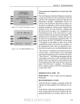
The purpose of this section of the manual is to describe the procedures for cassette closing and replenishment. Information concerning note handling and quality issues are explained where appropriate.
DISPENSING MECHANISMS
* PLEASE READ *
The Model RL1600 production units are equipped with the MiniMech dispenser.
Also, there will only be one style of cabinet offered which can accommodate the dispenser mentioned
above.
Currency capacity depends upon the dispenser mechanism installed in the ATM, but is also affected by
note quality and thickness. Typical capacities are provided in the following table: DO NOT be tempted to
=
"
RL1600 DISPENSING MECHANISM
DISPENSER
CASSETTE
Minimech
Single
RECOMMENDED
MAXIMUM CAPACITY
750 Notes
REJECTED NOTE
CAPACITY
Less than 100
=
!+
#
#
#!"
customer’s withdrawal request. The purpose of the reject area or cassette is to accept and hold notes that have
been transferred from the note cassette but not dispensed. Some situations that could cause the mechanism
to reject notes are:
(1) Multiple notes stuck together
(2) Note width too short or long.
Other conditions that could cause a reject are described in the next section, Note Condition.
**CAUTION**
DO NOT RECYCLE REJECTED NOTES INTO A CASSETTE!
Doing so could cause more rejects and/or currency jams.
16
CASSETTE CLOSE / CASH REPLENISHMENT
NOTE CONDITION
!+
#
{
+
|!
+
_!
!
_!
#
!
\
!
+
}"~
#
=
#
#
'
{
#!
*
#
!
}~
"
not possess any of the defects listed here:
USED NOTE DEFECTS
Â$=
};~
!+
!#
#
Â
~
#
#
!
ÂTears, holes, or missing sections in the body of the currency.
ÂTape on the surface of the currency used for repairing, patching or any other purpose.
ÂStaples, pins, or any other foreign body attached to the notes.
Â
#
#
`
~
ÂTwo or more notes joined by any means.
ÂExcessively crumpled or crinkled.
PREPARING NOTES
Use the following procedures to prepare notes before inserting them into a note cassette.
PREPARING USED NOTES
ÂRemove the band around each bundle of notes.
ÂRemove foreign objects (e.g. pins, paper clips, crumbs,
etc.).
ÂRemove torn or very worn notes.
ÂStraighten any folded notes.
Figure 3-1. Removing
band.
Figure 3-2. Removing
torn/worn notes.
NEW OR UNCIRCULATED NOTES
Remove the band around each bundle of notes. Separate the notes from each other by:
ÂStriking the bundle hard against the edge of a table or similar object.
ÂFlipping through each bundle of notes in both directions at each end.
ÂUsing a note counter.
17
MODEL RL1600 U SER M ANUAL
CASSETTE CLOSE PROCEDURES
Follow Access instructions to enter MANAGEMENT FUNCTIONS. Select TERMINAL CLOSE
FUNCTIONS. Select CASSETTE CLOSE.
Select cassette(s) to Close. A check mark
( √ ) identifies which cassette(s) are selected.
Press <Enter>.
After cassette(s) have been reinserted in
the dispenser, press <Enter>.
Place selected cassette(s) IN SERVICE.
Press <Enter>.
A Close report is displayed to be printed
or saved. This operation will reset the number
of bills in the cassette(s) to ZERO (0). Press
<Enter>.
Enter Cassette Quantity (number of notes,
NOT value) for the selected cassette(s). Press
<Enter> to accept entry. Repeat for each
selected cassette.
Remove and Replenish the selected
cassette(s).
Procedures for cassette replenishment are
on the following pages.
A Trial Cassette Close report automatically
is displayed to be printed or saved. Print and
retain a copy for starting point reference. Press
<Enter> to return to Close functions.
18
CASSETTE CLOSE / CASH REPLENISHMENT
Replenish Cassette
Mech 10 (MiniMech)
1. Unlock and open the security cabinet door.
2. To remove the note tray, grasp the tray handle and slide the tray out of the mecha
Q
|
=
!#
3. Remove any rejected notes. The reject compartment is located nearest the handle
side of the tray.
Removing rejected notes.
Removing note tray from the dispensing
mechanism.
Note: You may wish to record the number of notes removed from the reject compartment for use when balancing the note tray against the cassette/day close records.
Loading the Note Tray
1. Move the pusher plate to the rear of the tray (toward the handle). Ensure the pusher
plate is fully back. Maintain pressure on the pusher plate as needed while loading
notes.
2. Count the number of bills that remain in the cassette, if any. Next, count the number
of bills that are being added into the cassette.
3. Add the number of bills being placed
into the cassette to the number that re
}~
!+
#
bills will be entered in the “Enter Cas
!~
Load note tray with currency.
19
MODEL RL1600 USER MANUAL
Q
!
$
#
+
packer plate when it is fully retracted and the currency. This will allow the packer
plate to compress the currency.
5. Release the pusher plate against the notes.
6. Using the handle, slide the note tray into the dispensing mechanism. Make sure the
note tray is fully inserted!
Release pusher plate
Slide note tray into dispenser mechanism.
7. Close and lock the security container.
20
SECTION 4
GENERAL MAINTENANCE
21
MODEL RL1600 USER MANUAL
INTRODUCTION
This section of the manual covers preventive and corrective maintenance procedures appropriate for user
personnel. The following areas are covered:
1.
REPLENISHING RECEIPT PAPER. Describes how to replace a spent receipt paper roll.
2.
CLEANING THE ENCLOSURE. The proper way to clean the ATM housing.
3.
CARD READER CLEANING. The recommended card reader cleaning technique.
*Important*
DO NOT
REPLENISHING THE RECEIPT PAPER
NOTE: This operation must be completed with the AC power applied to the ATM.
1.
Open the control panel by unlocking the top enclosure and pulling the hinged door forward.
2.
If paper remains on the roll, cut or tear the paper between the roll and the printer.
DO NOT
"#$%
%
'
Cut paper between the roll and printer feed path.
22
GENERAL MAINTENANCE
3.
Use the receipt printer feed button to feed the paper through the paper path until all paper comes out
the front of the printer.
4.
Remove the paper and spool from the paper bracket.
Paper feed button location.
5.
Remove paper roll from bracket.
Remove the tab securing the end of the new paper roll to itself. Use scissors to cut off all of the paper
up to and including the glue tab.
Remove the plastic spindle from the old paper roll and insert into the new roll of paper. Use a 4-inch
roll of 60 mm wide thermal paper, printer applicable.
Be sure the spindle is inserted so that the paper will feed from the TOP of the roll when it is installed
on the paper bracket.
6.
Place the new roll back on the paper bracket by sliding the small, slotted end of the spindle onto the
slot in the bracket as shown. ()!
Place paper roll on bracket. Paper feeds from top of roll!
23
MODEL RL1600 USER MANUAL
7.
Feed the end of the paper into the printer take-up slot. The printer will activate and automatically feed
the paper through the printer and slightly out the front of the control panel.
8.
If the printer does not feed automatically, open the printer assembly by pulling the release pin on the
side.
Feed paper into the printer take-up slot.
9.
Release pin location.
Rotate the printer towards the front of the unit.
10. Check the blue lever to ensure it’s in the correct position as shown. If it is not in the position shown,
move the lever (moves in 3 positions) to the correct position. Close the printer assembly and perform
step 7 again. Ensure the printer is secured by the release pin.
Rotate printer open.
Blue tension lever (correct position).
11. Close and lock the control panel. Go to MANAGEMENT FUNCTIONS > DIAGNOSTICS and perform a RESET/
TEST PRINTER.
24
GENERAL MAINTENANCE
CLEANING THE ENCLOSURE
$%
#
!+<
"
!
=<
ing of the front panel and the plastic enclosure may be desirable. A soft dry or slightly damp cloth may be
used for cleaning. For best results, use a weak solution of a mild detergent and water.
+
%"
,
CLEANING THE DISPLAY
The Liquid Crystal Display (LCD) on the front of the ATM has a plastic protective window that should be
cleaned only with a soft cloth, dampened with a weak solution of a mild detergent and water.
, "
$
$ $
,
$
%
CARD READER CLEANING
Special cleaning cards (P/N 06200-00055) are available for proper maintenance of the card reader. The
reader should be cleaned at least once a month by inserting and removing a cleaning card, as shown below.
It may be necessary to clean the card reader more often in locations that see heavy usage.
1.
Remove the cleaning card from the sealed pouch.
2.
Insert the cleaning card into the card reader and move in and out several times.
3.
Remove the cleaning card and turn over to use other side.
4.
Insert again several times.
5.
Remove cleaning card and discard. They are designed to be used only once.
25
MODEL RL1600 USER MANUAL
THIS PAGE INTENTIONALLY LEFT BLANK
26
SUPPLEMENT A
T5 AND T7 PCI-EPP
BATTERY REPLACEMENT PROCEDURES
SA-1
T5 PCI-EPP BATTERY REPLACEMENT
** CAUTION **
You must not remove battery from EPP without FIRST connecting a new
battery! This EPP will be permanently damaged if unpowered and battery is
removed before connecting a new battery!
Battery Case
Spare battery
connection
EXISTING BATTERY - DO NOT REMOVE BEFORE
CONNECTING A SPARE BATTERY FIRST!
The spare battery for the T5 PCI-EPP may be purchased from Triton Systems:
P/N 01300-00025 (T5 PCI-EPP Lithium Backup Battery)
SA-2
SUPPLEMENT A - T5 / T7 PCI-EPP BATTERY REPLACEMENT PROCEDURES
T7 PCI-EPP BATTERY REPLACEMENT
* IMPORTANT*
You may remove the battery without risk of damage to the EPP. You have
approximately 1-2 minutes to replace with a spare battery before losing the
data stored (keys, passwords) in the keypad.
Battery Case
The spare battery for the T7 PCI-EPP may be purchased from Triton Systems:
P/N 01300-00023 (T7 PCI-EPP Lithium Battery)
SA-3
THIS PAGE INTENTIONALLY LEFT BLANK
SA-4
T5 PCI-EPP
KEY
SUPPLEMENT B
MANAGEMENT PROCEDURES
T7 PCI-EPP
T5 - T7
PCI-EPP (T5) / K EY M ANAGEMENT P ROCEDURES
DIFFERENCES WITH THE T5 PCI-EPP KEYPAD
YOU MUST NOT REMOVE BATTERY FROM EPP WITHOUT FIRST CONNECTING A NEW BATTERY! THIS
T5 EPP WILL BE PERMANENTLY DAMAGED IF UNPOWERED AND BATTERY IS REMOVED BEFORE CONNECTING A NEW
BATTERY!
USER PASSWORDS MUST BE AT LEAST 8 CHARACTERS, RATHER THAN 6.
EPP WILL PROMPT WITH ERROR IF FEWER CHARACTERS ENTERED AND THEN TAKE YOU BACK TO PASSWORD
ENTRY AT POINT YOU LEFT OFF.
THERE IS NO WAY TO CLEAR THE PASSWORD . HIT <C ANCEL > AND START OVER.
NO <CLEAR> OR <BACKSPACE> ON KEY ENTRY.
IF ERROR IS MADE IN KEY ENTRY, HIT <CANCEL> AND START KEY ENTRY OVER FROM BEGINNING OF FIRST KEY
HALF.
YOU MAY ONLY ENTER IN NEW KEYS - NO CHANGE KEY FUNCTIONALITY.
YOU HAVE 10 MINUTES TO ENTER IN BOTH U SER PASSWORDS BEFORE TIMEOUT.
–
IF TIMEOUT OCCURS, YOU MUST START KEY ENTRY OVER FROM SCRATCH .
–
THIS WILL AFFECT STAGING OF UNITS!
–
CANNOT ENTER ONE KEY HALF AT WAREHOUSE AND OTHER HALF IN FIELD.
PASSWORD ENTRY – CLEAR WILL TAKE YOU BACK TO KEY MANAGEMENT PAGE.
–
RE-ENTER PASSWORD.
SB-2
SUPPLEMENT B - KEY MANAGEMENT PROCEDURES
KEY MANAGEMENT PROCEDURES (W/T5 PCI-EPP INSTALLED)
ENTER MANAGEMENT FUNCTIONS > MAIN MENU
NOTE: PREVIOUSLY , USERS HAD TO ENTER THE
INITIAL PASSWORD OF SIX (6) “ZEROS” BEFORE BEING
ALLOWED TO SET THE PASSWORDS. THIS IS NO LONGER
REQUIRED (FOR T5 PCI-EPP ONLY).
> KEY MANAGEMENT.
SELECT “S ET U SER 1 PASSWORD ” OPTION.
ENTER NEW PASSWORD FOR USER 1. PASSWORDS CAN
BE ANYWHERE FROM ‘8’ TO ‘16’ DECIMAL DIGITS. PRESS
<ENTER>.
YOU
WILL BE PROMPTED AGAIN TO CONFIRM
THE NEW PASSWORD .
R E - ENTER
NEW PASSWORD .
PRESS <ENTER>.
AFTER THE PASSWORD IS INITIALIZED, THE “SET USER
1 PASSWORD ” OPTION CHANGES TO “CHANGE USER 1
P ASSWORD ”.
THE “SET PASSWORD INITIALIZATION” PROMPT
APPEARS.
PRESS <ENTER>.
SELECT “SET PASSWORD” OPTION.
NEXT, SELECT “SET USER 2 PASSWORD” OPTION. FOLLOW THE SAME PROCEDURE FOR ENTERING A
NEW PASSWORD FOR U SER 2.
WHEN COMPLETED, THE “SET USER 2 PASSWORD” OPTION WILL CHANGE TO “CHANGE USER 2 PASSWORD”.
AFTER COMPLETION, HIT <CANCEL > TO ENTER MAS TER KEYS SCREEN (STEP 5).
SB-3
T5 - T7
SELECT “ENTER MASTER KEYS” OPTION.
USER 1 ENTERS THE FIRST KEY PART (32 CHARACTERS). REFERENCE THE KEY LAYOUT DISPLAY BELOW.
THE MAIN KEYPAD WILL MIRROR THE NUMBER/ALPHANUMERIC KEYS.
AFTER ENTERING THE KEYS, PRESS THE <ENTER> OPTION ON THE RIGHT-SIDE FUNCTION KEY <F7>.
IMPORTANT: T HE REST OF THE PROCEDURES
MUST BE COMPLETED WITHIN A 10
MINUTE PERIOD. I F T H E P R O C E S S TA K E S
LONGER THAN THAT, THE KEY PARTS WILL NOT BE ABLE
TO BE COMBINED !
ENTER U SER 1 PASSWORD. PRESS <ENTER>.
ENTER U SER 2 PASSWORD. PRESS <ENTER>.
F5
F7
SELECT “ENTER PIN MASTER KEY” OPTION.
SB-4
SUPPLEMENT B - KEY MANAGEMENT PROCEDURES
11
THE “CHECK DIGITS” PROMPT APPEARS.
PRESS <ENTER>.
A PROMPT APPEARS TO ENTER THE SECOND KEY PART.
PRESS <ENTER>.
USER 2 ENTERS THE SECOND KEY PART (32 CHARACTERS). REFER TO STEP 8 FOR ENTERING KEYS.
THE “CHECK DIGITS” PROMPT APPEARS.
YOU WILL BE PROMPTED THAT THE KEY WAS SUCCESS FULLY CHANGED.
REPEAT SEQUENCE FOR ENTERING MAC MASTER KEY ,
IF REQUIRED.
SB-5
T5 - T7
KEY MANAGEMENT PROCEDURES (W/T7 PCI-EPP INSTALLED)
ENTER MANAGEMENT FUNCTIONS > MAIN MENU
THE T7 USER PASSWORDS ARE INITIALLY SET TO
SIX (6) “ZEROS (SIMILAR TO VEPP) BEFORE BEING AL LOWED TO SET THE PASSWORDS .
> KEY MANAGEMENT.
SELECT “S ET U SER 1 PASSWORD ” OPTION.
ENTER NEW PASSWORD FOR USER 1. PASSWORDS CAN
BE ANYWHERE FROM ‘6’ TO ‘14’ DECIMAL DIGITS. PRESS
<ENTER>.
YOU
WILL BE PROMPTED AGAIN TO CONFIRM
THE NEW PASSWORD .
R E - ENTER
NEW PASSWORD .
PRESS <ENTER>.
AFTER THE PASSWORD IS INITIALIZED, THE “SET USER
1 PASSWORD ” OPTION CHANGES TO “CHANGE USER 1
P ASSWORD ”.
THE “SET PASSWORD INITIALIZATION” PROMPT
APPEARS.
PRESS <ENTER>.
SELECT “SET PASSWORD” OPTION.
NEXT, SELECT “SET USER 2 PASSWORD” OPFOLLOW THE SAME PROCEDURE FOR ENTERING A
PASSWORD FOR USER 2.
TION.
NEW
WHEN COMPLETED, THE “SET USER 2 PASSWORD” OPTION WILL CHANGE TO “CHANGE USER 2 PASSWORD”.
AFTER COMPLETION, HIT <CANCEL > TO ENTER MAS TER KEYS SCREEN (STEP 5).
SB-6
SUPPLEMENT B - KEY MANAGEMENT PROCEDURES
SELECT “ENTER MASTER KEYS” OPTION.
USE THE <ARROW> KEY TO TOGGLE BETWEEN
“NEW KEY” OR “ADD PART” (TO AN EXISTING KEY).
PRESS <ENTER> FOR THE APPLICABLE ENTRY.
ENTER USER 1 PASSWORD. PRESS <ENTER>.
ENTER USER 2 PASSWORD. PRESS <ENTER>.
USER 1 ENTERS THE FIRST KEY PART (32 CHARACTERS). REFERENCE THE KEY LAYOUT DISPLAY BELOW.
THE MAIN KEYPAD WILL MIRROR THE NUMBER/ALPHA NUMERIC KEYS.
AFTER ENTERING THE KEYS, PRESS THE <ENTER> OPTION ON THE RIGHT-SIDE FUNCTION KEY <F7>.
SELECT “ENTER PIN MASTER KEY” OPTION.
SB-7
THE “CHECK DIGITS” PROMPT APPEARS .
PRESS <ENTER>.
T5 - T7
A PROMPT APPEARS TO ENTER THE SECOND KEY PART.
PRESS <ENTER>.
USER 2 ENTERS THE SECOND KEY PART (32 CHARACTERS). REFER TO STEP 9 FOR ENTERING KEYS.
11
YOU WILL BE PROMPTED THAT THE KEY WAS SUCCESSFULLY CHANGED.
12
REPEAT SEQUENCE FOR ENTERING MAC MASTER KEY ,
IF REQUIRED.
THE “CHECK DIGITS” PROMPT APPEARS.
SB-8