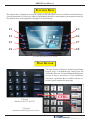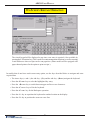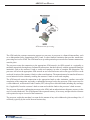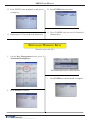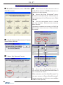
1
AUTOMATED TELLER MACHINE USER MANUAL TDN 07103-00339 CORPORATE HEADQUARTERS: 21405 B STREET LONG BEACH, MS. 39560 PHONE: (800) 259-6672 PHONE: (228) 575-3100 FAX: (228) 575-3101 © 2013 Triton. All Rights Reserved. TRITON logo is a registered trademark of Triton Systems of Delaware, LLC. ARGO USER MANUAL DOCUMENT UPDATES February 19, 2013 Original February 21, 2013 Added camera cutout site info March 7, 2013 Added specification table March 28, 2013 Changed card reader cleaning part from 06200-00055 to 05010-00024. July 26, 2013 Removed all TDM250 & motorized card reader references December 17, 2013 Added Relative Humidity for Australia notes in Section 1 Page 6. ii ARGO USER MANUAL The Triton ARGO ATM is a lobby terminal designed for indoor use only. The ARGO line includes models RL1713, RL27XY, and RL63XY. The following sections provide the steps used to understand and operate all functions supported by the ARGO ATM. The ARGO’s larger screens and touch technology simplifies the user experience and operation. TABLE OF CONTENTS Section 1: Introduction ......................................................................................................1 Feature Highlights........................................................................................2 Standard Features .........................................................................................5 Specifications ...............................................................................................6 Section 2: Basic Operation ................................................................................................7 Introduction ..................................................................................................8 Control Panel Layout ...................................................................................8 Function Keys ..............................................................................................9 Main Keypad................................................................................................9 On-Screen Keypad Operation ....................................................................10 Menu-Based Operation ..............................................................................11 Customer Transactions ...............................................................................13 Voice-Enabled Transaction ........................................................................15 E-Receipt Technology ................................................................................15 Section 3: Cassette Close / Cash Replenishment ...........................................................17 Introduction ................................................................................................18 Dispensing Mechanisms ............................................................................18 Note Condition ...........................................................................................19 Preparing Notes..........................................................................................19 Cassette Close Procedures .........................................................................20 Replenish Cassette Procedures ..................................................................21 Section 4: General Maintenance .....................................................................................29 Introduction ................................................................................................31 Replenishing the Receipt Paper .................................................................31 Cleaning the Enclosure ..............................................................................34 Cleaning the Display ..................................................................................34 Card Reader Cleaning ................................................................................34 iii ARGO USER MANUAL Section 5: Setup Basics ....................................................................................................36 Introduction ................................................................................................37 Logon .........................................................................................................37 Change Master Password ...........................................................................38 Set Denomination.......................................................................................39 Enter Host Phone Number .........................................................................41 Enter Terminal ID ......................................................................................43 Enter Master Keys......................................................................................44 Download Working Keys ...........................................................................48 APPENDIX A - SOFTWARE LICENSE AGREEMENT / COMPLIANCE STATEMENTS APPENDIX B - WARRANTY STATEMENT APPENDIX C - ELECTRONIC COMBINATION LOCKS APPENDIX D - MECHANICAL COMBINATION LOCKS SUPPLEMENT A -T7 T5 BATTERY REPLACEMENT PROCEDURES SUPPLEMENT B - KEY MANAGEMENT PURPOSE This guide covers the procedure of operating all functions of a Triton ARGO ATM with security and ease of operation in mind. All units come with pre-loaded software; later updates will be made available online. Scope This manual applies to all service personnel involved in the process of maintaining, converting, or upgrading hardware and software on Triton ATMs nationwide and abroad. APPLICATION This user guide provides information, methods and easy to follow instructions for the operational settings of the Triton ARGO ATM. It contains information on set-up functions, maintenance, diagnostics, communication systems and security settings. iv SECTION 1: INTRODUCTION ARGO USER MANUAL Once unit is unpacked, set up, and power restored, you will be asked to set up passwords and security basics. The user manual describes the operating features and shows how to perform procedures typically performed by the owner/operator personnel. Below are the basic features of the ARGO. Varying options are also available. FEATURE HIGHLIGHTS INTEGRATED LIGHTED TOPPER (OPTIONAL HIGH TOPPER AVAILABLE) CAMERA READY CUTOUT 12.1-INCH SCREEN (ALSO AVAILABLE IN 7” FULLY TOUCH SCREEN) TOUCH SCREEN FUNCTION KEYS LED KEYBOARD ILLUMINATION ADA APPROVED HEADPHONE PORT RECEIPT PRINTER CARD READER ALPHANUMERIC KEYPAD The ARGO ARGO RL63XY RL63XY with with 112.1” 2 1” ttouch ouch sscreen creen ffunction unction kkeys eys The 2 ARGO USER MANUAL Important features of the ARGO series ATM are highlighted in the following list: ► Highly reliable, state-of-the-art operating system PC platform design. The ARGO uses Microsoft® Windows® CE 5.0 operating system with Triton’s X2 technology. Supports Windows file formats for adding custom logos and advertisements. In addition, it features Triton’s completely custom design X2 motherboard. ► Modular architecture eases troubleshooting and servicing. ► Front-access unit accommodates single cassette (MiniMech, SDD or SCDU) and dual cassette (NMD50 or HCDU). The ARGO with MiniMech features a shallow cabinet design while the other models feature a deep cabinet design. ► 7” fully touch widescreen screen display and 12.1” color LCD screen display with touch screen function keys. 7” model introduces E-receipt technology. ► T7 or T5 PCI-compliant EPP to comply with international encryption standards and Triple DES compliant. ► Easy to install (small footprint design makes placement easier) and configure terminal parameters by software. ► Supports communication types TCP/IP (standard), dial-up (56K baud Triton USB modem) and optional wireless (TDL Gateway). (Note: For wireless option, please contact your account representative for more information). 7” display uses capcitive touch screen technology. ► Multi-function, dip-style card reader supports magnetic stripe cards or “smart” cards that conform to the EMV standard. ► Some models allow users to enter e-mail address or phone number on the on-screen keypad to have a receipt e-mailed or texted to them. Other models are equipped with graphics-capable 60 or 80 mm thermal printer that prints, cuts, prints receipts, coupons, and management reports. ► Mechanical (standard) or electronic combination lock (optional). ► Supports remote setup, configuration, and monitoring via Triton Connect™ ATM monitoring software. ► LED-backlit signage standard. Available with optional high-topper for deep cabinet models. Optional LED backlit high-topper 3 ARGO USER MANUAL ► High-capacity electronic journal stores transaction details for later printout and analysis. ► Satisfies Americans with Disabilities Act (ADA) specifications for height and access; audio transactions for the visually impaired. Complies with UK accessibility guidelines (DDA) and California access compliance, Title 24. ► Dispenses U.S. and international currency types. ► Camera ready. Cutout at top of fascia is available for a camera to be installed. Camera kit available. HOME FAVORITES MENU Home Favorites - Allows one button short cuts to those areas of Management Functions most often visited. Can be used for individuals to allow quick access to their areas of responsibility, such as Cassette Close and Day Close for Cash Replenishers. Press “0” to access the traditional Main Menu. MAIN MENU Main Menu - Gateway to configuration, password maintenance, and more. A variety of screen options from the main menu will be detailed in later sections of this manual. Shown above are the Home Favorites and Main Menu screen giving access to management, terminal, diagnostic, key management and other functions available on ARGO models. 4 ARGO USER MANUAL STANDARD FEATURES ► MANAGEMENT FUNCTIONS. Enable extensive control and customization of operating parameters. See X-SCALE/X2 CONFIGURATION MANUAL on website. ► PASSWORD PROTECTION. Management Functions and Key Management areas are protected with passwords. ► MAC ENCRYPTION SUPPORT. Message Authentication Code (MAC) data encryption protocol. Provides increased protection for message traffic to and from the ATM. Triple DES compliant. ► SSL Support. TCP/IP with Secure Socket Layer adds another level of ATM to Host communications security. ► PCI COMPLIANT ENCRYPTING PIN PAD (EPP) ENTRY DEVICE SUPPORT. Secure EPP device encrypts the customer PIN during a transaction. Triple DES and PCI compliant. ► MULTI-LANGUAGE SUPPORT. Enables the customer to select a preferred language (such as French or Spanish) for customer screens and receipts. ► TRANSACTION AND ACCOUNT TYPE CONFIGURATION. Enables selection of transactions (transfers or balance inquiries) or accounts (savings or credit card) that will be presented to the customer. Does not affect availability of checking account withdrawal. ► STATUS MONITORING. The ATM can periodically transfer status information to the host processor. In addition, Triton Connect™ remote monitoring software can be used to view the journal, monitor operation and alarm conditions, update operating parameters, and reset the terminal. ► BUSINESS HOURS OR VAULT. Cabinets available in UL 291 Business Hours Service or UL 291 Level 1 Safe models. 5 ARGO USER MANUAL SPECIFICATIONS ITEM 7” DISPLAY Operating System RAM Flash Drive TCP/IP Power Requirements • • • • Temperature Range Relative Humidity (non-condensing) LCD Resolution LCD Backlight Modem EMC Standard • • 12.1” DISPLAY Windows CE 5.0 64 MB 128 MB 10 BASE-T/100 BASE-TX with SSL Max current: 3.3A @ 115 VRMS at 60 Hz Voltage: 100-240 VRMS @ 50/60 Hz Idle Power Consumption: 0.6A @ 115 VAC at 60 Hz Max Load Power Consumption: 396 Watts @ 120VAC 10°C to 40°C 50°F to 104°F 20% - 80% 20% - 70% Australian Currency 800 x 480; Capacitive Touch LED 56,000 bps EN55024 • • • • • • Windows CE 5.0 128 MB 128 MB 10 BASE-T/100 BASE-TX with SSL Max current: 3.3A @ 115 VRMS at 60 Hz Voltage: 100-240 VRMS @ 50/60 Hz Idle Power Consumption: 0.6A @ 115 VAC at 60 Hz Max Load Power Consumption: 396 Watts @ 120VAC 10°C to 40°C 50°F to 104°F 20% - 80% 20% - 70% Australian Currency 800 x 600 LED 56,000 bps EN55024 See the ARGO Installation Manual for further specifications and important safety issues for installing units. 6 SECTION 2: BASIC OPERATION ARGO USER MANUAL INTRODUCTION This section describes the basic operation of the terminal. The following topics are covered: 1. CONTROL PANEL LAYOUT. Describes the layout of the terminal’s control panel. 2. KEYPAD OPERATION. Describes the use of the alphanumeric keypads. 3. MENU-BASED OPERATION. Gives a general overview of the terminal display interface. 4. CUSTOMER TRANSACTIONS. Summarizes the actions involved in typical customer transactions. In addition, the voice-enabled transactions feature is described. CONTROL PANEL LAYOUT The user interface of the terminal consists of the LCD screen, receipt chute, card reader, speaker, headphone jack (visually impaired), and 24 keys on three keypads. The Function keys are arranged in two four-key groups, one group on either side of the LCD display. The Function keys on the 7” touch screen display are on the screen. The main keypad consists of 10 alphanumeric keys, two arrow keys and four large control keys, all located in a 16-key group beneath the LCD screen. The main keypad and control keys have an integral raised Braille symbol to conform to the requirements of the Americans with Disabilities Act The 12.1 inch screen has touch-reactive F keys on the sides and most closely resembles previous ATM functionality. The F keys will respond even when the user wears gloves. The 7 inch screens are fully touch-reactive and have no external F Keys. The 7 inch screen is capacitive sensing and therefore requires human touch (no gloves) to operate. The introduction of E-receipt technology is available on this model. 12.1 inches with touch-reactive F keys 7 inch totally touch-reactive screen 8 ARGO USER MANUAL FUNCTION KEYS The eight (8) keys, arranged in two four-key groups on left and right of screen, are called screen function keys. A screen function key is only active when a corresponding function or menu option is present next to that key. The function keys are designated F1 through F8, as shown below. F1 F5 F2 F6 F3 F7 F4 F8 Function key layout on 12.1” screen. MAIN KEYPAD The entry of numeric characters via the encrypted main keypad, (left), is straightforward: simply press the desired key. However, in certain Management Function screens it may be necessary to enter alphabetic characters, a procedure that’s available with the onscreen keypad, explained on next page. CTRL T7 Keypad (Standard on RL1713, RL27XY) T5 Keypad (Standard on RL63XY, optional on others) 9 ARGO USER MANUAL ON-SCREEN KEYPAD OPERATION The virtual keypad will be displayed at any time a text entry is required. (Also available by pressing the F-8 function key.) This is used for certain management functions, as well as entering e-mail addresses where receipts can be sent paperless. (Some models will be equipped with paper thermal printers for the option to print receipts.) In models that do not have touch screen entry option, use the keys described below to navigate and enter required data. • The Arrow keys (< and >), the <8> key - (UP), and the <0> key - (DOWN) navigate the keyboard. • Press the <ENTER> key to select the highlighted key entry. • Press the <BLANK> key to switch between upper and lower case characters. • Press the <CANCEL> key to Exit the keyboard. • Press the <CLEAR> key for the Backspace operation. • Press the <1> key to reposition the keyboard to another location on the display. • Press the <2> key to position the cursor on a new line. 10 ARGO USER MANUAL MENU-BASED OPERATION The terminal operates as a menu driven system. Messages and menu options presented on the LCD display screen guide the user’s actions. The desired menu option is selected by pressing one of the keys located to the left and right of the display. For the purpose of security, many screens time-out after a preset time interval, usually 30 seconds. The time-out length may vary depending on the function being performed. When a screen time-out occurs, a screen is presented that asks the user if more time is needed. If the user chooses NO, the Customer Welcome screen will be presented. If YES is chosen, the user is returned to the function that was active prior to the time-out. If the user does not make a selection within an additional 30-second countdown period, the terminal will automatically go to the Customer Welcome screen. Ensure all procedures in the ARGO Installation Manual have been accomplished. The unit should be off, with the power cord and communications cable connected. Power on the unit by pressing the power switch on the power supply to the ON position. Shortly after the unit is turned on, the top menu will be displayed. An example top menu is shown below. From the top menu, you can either: Enter the terminal system management area by pressing the key next to MANAGEMENT FUNCTIONS. 1. Note: You will have to enter an appropriate password to view the Management Functions menu. Management Functions may also be entered by pressing and holding the CTRL key and then depressing the number 1 key and releasing both. 2. Activate the terminal to perform customer transactions by pressing the key next to CUSTOMER TRANSACTIONS. Note: On fully touch screen models, just press the displayed buttons to select your preferred option. 11 ARGO USER MANUAL Choosing Management will take you to the password screen. An Error Code of 246 WILL be displayed upon the first start up. You MUST change the master password before any other configuration operations will be allowed. The master password is actually made up of two parts, the ID and the password. The master ID is 00 and cannot be changed. What must be changed is the default master password for ID 00 of 1234. ► Management Functions can be entered from the Top Menu screen upon startup (representative screen on the previous page), or by pressing the “Blank Key” (lower right corner) and the number 1 at the same time. ► It will ask you to enter the ID and Password. Press 001234. It will take you to the new Favorites Menu. Press 0. ► It will then take you to the Main Menu. ► Select 4 Password Maintenance, then 1 Change User Password ► Enter the new password ONLY. You are user 00 and already logged in, so putting 00 here is not necessary. The new password can be 4-12 digits. Do not use birthdays, telephone numbers, social security numbers or the like. Make it something you can remember, but not so difficult as to be forgotten. Guard it closely. If the password is lost or forgotten, the password cannot be changed or recovered in the field. The main board must be returned to Triton for a reset. A service charge will apply. ► If you will have additional people that will be accomplishing closes and replenishing cassettes, you may add them and provide passwords here. New users can be ID 01 - 99. There are additional error messages that will appear, and must be cleared before the ATM will go into service. Refer to Section 5 of this document for the minimum setup requirements and document 07100-00016 XScale/ X2 Configuration Manual for additional terminal setup procedures. Take this opportunity to change the lock combination. Refer to Appendix C or D for your lock. The same rules for combination numbers as passwords apply. 12 ARGO USER MANUAL If you do not select a menu choice within 30 seconds, the terminal will automatically default to the Customer Welcome screen (a benefit of this feature is that in the event of a power interruption, the terminal will automatically begin accepting customer transactions shortly after power is restored). CUSTOMER TRANSACTIONS A customer begins a transaction by selecting from the Customer screen options. They insert their ATM card into the card reader of the terminal. The card must be inserted so that the magnetic stripe can be scanned by the card reader’s sensor. If the customer inserts the card incorrectly, a warning message will be displayed, accompanied by several beeps to get their attention. If there is a problem reading a card, make sure the customer is inserting the card correctly. Most problems are the result of inserting the card incorrectly. Once the card has been read successfully, a surcharge message, if applicable, may be displayed (the surcharge message may be displayed at the end of the customer’s transaction selection). The customer must then enter their secret Personal Identification Number (PIN) code. Once the PIN has been entered, the transaction type and account are selected, and the desired amount of the transaction, if needed. The transaction will be processed, typically in a matter of seconds. The figure following shows how ATM transactions are handled. If the transaction was processed successfully, the customer is prompted to retrieve the requested cash (for withdrawal transactions) and/or the applicable transaction receipt, as needed. If the transaction was declined, a short receipt indicating the problem is printed. 13 ARGO USER MANUAL ATM transaction processing. The ATM sends the customer transaction request to a processor. A processor is a financial intermediary, such as an Independent Sales Organization (ISO), bank, or other financial institution that provides transactionprocessing services for ATMs. The ATM must be set up with a particular processor before customer transactions can take place. The processor routes the transaction to the appropriate ATM network. An ATM network is a regionally or nationally organized clearing house for financial transactions, that deals directly with the appropriate financial institution, such as the customer’s bank or credit card company, in order to complete the transaction. The processor will select the appropriate ATM network to use based on factors such as the type of ATM or credit card used, location of the customer’s bank, or other considerations. The transaction may be transferred between several networks before ultimately reaching the customer’s bank or credit card company. The ATM network routes the transaction to the appropriate bank or other institution, confirms successful completion of the transaction, and sends a confirmation message back to the processor. If the request was for a cash withdrawal, an Electronic Funds Transfer (EFT) takes place to debit the funds (including any surcharge fee, if applicable) from the customer’s bank account and credit the funds to the processor’s bank account. The processor forwards a confirmation message to the ATM (and an authorization to dispense currency, in the case of a cash withdrawal). The ATM dispenses the requested currency, if necessary, and provides the customer with a printed receipt as a record of the transaction. The processor credits the merchant’s account for the amount of any cash withdrawals (plus surcharge fees, if collected), typically by the end of the next business day. 14 ARGO USER MANUAL VOICE-ENABLED TRANSACTION The terminal provides voice feedback via an integrated output jack, enabling sight-impaired users to plug in a set of headphones and receive spoken instructions to assist them in using the ATM. A raised symbol helps a user locate the headphone jack. The ATM will automatically detect when a headphone has been plugged into the jack, and will immediately switch into voice mode. Initially, a brief spoken tutorial will orientate the customer to the ATM control panel interface. Once the customer begins a transaction, spoken prompts will provide feedback and guide the customer through the successful accomplishment of the transaction. Headphone jack location. (Typical) E-RECEIPT TECHNOLOGY The seven inch screen terminals provide for E-Receipt technology. The customer is offered the choice of (a) the standard printed receipt, (b) having the receipt sent to his phone as a text message, or (c) sent to an E-mail account. The E-mail information is not retained by the ATM or Triton, and will not be used for any marketing purposes. The account is not shown on the screen, only the * figures as the account is entered. NOTE: ► A seven inch screen without a printer MUST use E-Receipt or no receipt. ► A seven inch screen with printer can be configured to allow E-Receipt choice. (From the Main Menu: 6 Terminal Configuration > 0 More Options > 6 Electronic Receipts) ► The 12 inch screen model does not allow for E-Receipt operation. 15 ARGO USER MANUAL 7” ARGO with printer and topper 16 SECTION 3: CASSETTE CLOSE / CASH REPLENISHMENT SCDU HCDU MiniMech SDD NMD50 ARGO USER MANUAL INTRODUCTION The purpose of this section of the manual is to describe the procedures for cassette closing and replenishment. Information concerning note handling and quality issues are explained where appropriate. DISPENSING MECHANISMS * PLEASE READ * The ARGO Model RL1713 production units are equipped with the MiniMech dispenser and have the shallow cabinet design. The ARGO Model RL27XY (7 inch screen) and the ARGO Model RL63XY (12.1 inch screen) are equipped with one of the following dipsenser types: SCDU, HCDU, SDD or NMD50. These models have the deep cabinet design. Currency capacity depends upon the dispenser mechanism installed in the ATM, but is also affected by note quality and thickness. Typical capacities are provided in the following table: DO NOT be tempted to over fill the cassette. ARGO DISPENSING MECHANISM DISPENSER CASSETTE MiniMech SDD SCDU HCDU NMD50 Single Single Single Dual Dual RECOMMENDED MAXIMUM CAPACITY 750-1000 Notes 1700-1800 Notes 1000 Notes 3500 Notes (1750 each) 3500-4000 (1750-2000 each) REJECTED NOTE CAPACITY Less than 100 Less than 100 Less than 100 Less than 100 Less than 100 The dispensing mechanism delivers the appropriate number of notes from the note cassette to fulfill the customer’s withdrawal request. The purpose of the reject area or cassette is to accept and hold notes that have been transferred from the note cassette but not dispensed. Some situations that could cause the mechanism to reject notes are: (1) Multiple notes stuck together (2) Note width too short or long. Other conditions that could cause a reject are described in the following section, NOTE CONDITION. **CAUTION** DO NOT RECYCLE REJECTED NOTES INTO A CASSETTE! DOING SO COULD CAUSE MORE REJECTS AND/OR CURRENCY JAMS. 18 ARGO USER MANUAL NOTE CONDITION The number of rejects can be directly influenced by the technique used to load the cassettes and the quality of the currency. Notes loaded into the mechanism cassettes must be in fit condition if a high level of performance (low reject and failure rate) is expected from the unit. Fit notes are defined as those that do not possess any of the defects listed here: Used Note Defects Adhesive or sticky substances on the surface of the paper. Tears extending more than 1/2” from the edge of the currency. Tape on the surface of the currency used for repairing, patching or any other purpose. Staples, pins, or any other foreign body attached to the notes. Corner folds of a size greater than 1/2” on either axis. Two or more notes joined by any means. Excessively crumpled or crinkled notes. Tears, holes, or missing sections in the body of the currency. PREPARING NOTES Use the following procedures to prepare notes before inserting them into a note cassette. Preparing Used Notes Remove the band around each bundle of notes. Remove foreign objects (e.g. pins, paper clips, crumbs, etc.). Remove torn or very worn notes. Removing band. Straighten any folded notes. NEW OR UNCIRCULATED NOTES Remove the band around each bundle of notes. Separate the notes from each other by: Striking the bundle hard against the edge of a table or similar object. Flipping through each bundle of notes in both directions at each end. Using a note counter (highly recommended). 19 Removing torn/worn notes. ARGO USER MANUAL CASSETTE CLOSE PROCEDURES Follow access instructions to enter MANAGEMENT FUNCTIONS. Select TERMINAL CLOSE FUNCTIONS. Select CASSETTE CLOSE. After cassette has been reinserted in the dispenser, press Enter. Select cassette to close. A check mark () identifies which cassette is selected. “A” is selected by default. Press Enter. (Example shows only one cassette available.) Place selected cassette IN SERVICE. “A” will be in service. Press Enter. A Close report is displayed to be printed or saved. This operation will reset the number of bills in the cassette to ZERO (0). Press Enter. Enter Cassette Quantity (total number of notes, NOT value) for the selected cassette. Press Enter to accept entry. Remove and replenish the selected cassette. Procedures for cassette replenishment are on the following pages. A Trial Cassette Close report automatically is displayed to be printed or saved. Print and retain a copy for starting point reference. Press <Enter> to return to Close functions. 20 ARGO USER MANUAL REPLENISH CASSETTE PROCEDURES SCDU/HCDU 1. Unlock and open the security cabinet door. 2. Remove any rejected notes. The reject compartment is located above the cassette. 3. To remove the note tray, grasp the tray handle, lift slightly, and slide the tray out of the mechanism. Place the note tray on a flat level surface. Use the security key to unlock the cassette, and open the lid. Removing note tray from the dispensing mechanism. Removing rejected notes. Note: You may wish to record the number of notes removed from the reject compartment for use when balancing the note tray against the cassette/day close records. Loading the Note Cassette 1. Pull the packer plate to the rear of the tray (toward the handle). Ensure the packer plate is fully back. Maintain pressure on the packer plate as needed while loading notes. 2. Count the number of bills that remain in the cassette, if any. Next, count the number of bills that are being added into the cassette. 3. Add the number of bills being placed into the cassette to the number that remained. The total number of these bills will be entered in the Enter Cassette Quantity option (shown in step 6 of CASSETTE CLOSE PROCEDURES on previous page). 4. Place the currency into the cassette. Allow at least one inch of clearance between the packer plate when it is fully retracted and the currency. This will allow the packer plate to compress the currency. Do not try to over fill. 21 Pull packer plate back before loading notes. ARGO USER MANUAL 5. Release the packer plate against the notes. 6. Close the lid and lock with the security key. 7. Using the handle, slide the note tray into the dispensing mechanism. Make sure the note tray is fully inserted! 8. HCDU- repeat steps 1-7 for additional cassette. 9. Ensure the Reject door is closed. Close and lock the security container. SDD 1. Unlock/Open the dispenser security door. Grasp the cassette handle and remove the cassette. 2. Cassette MUST BE PRIMED with the cassette key before inserting on the loading tray. Insert key and turn clockwise to show GREEN indicator in window. Green window Cassette Primed ***WARNING*** IF RED IS INDICATED IN THE WINDOW ON THE SIDE OF THE CURRENCY CASSETTE, NEVER ATTEMPT TO INSERT THE CASSETTE INTO THE DISPENSER OR THE LOADING TRAY! 22 ARGO USER MANUAL 3. Slide cassette onto the loading tray. Lift lid to expose the reject tray. Remove any rejected notes. DO NOT recycle rejected notes! Cassette on Loading Tray Lid open to expose Reject Bin 4. Lift the reject tray. Push the packer plate to rear of cassette and latch in place. 5. Count the number of bills that remain in the cassette, if any. Count the number of bills that are being added to the remaining notes. The total number of these bills will be entered in the Enter Cassette Quantity prompt (shown in step 6 of CASSETTE CLOSE PROCEDURES). 6. Place currency in the cassette and slowly release the hold-back latch allowing the packer plate to move forward against the notes. Close the cassette lid. 7. Remove cassette from loading tray. Insert the cassette key and “PRIME” the cassette (Green indicator). Install the cassette into the dispenser. 8. Close and lock the security cabinet. 23 ARGO USER MANUAL MINIMECH 1. Unlock and open the security cabinet door. 2. To remove the note tray, grasp the tray handle and slide the tray out of the mechanism. Place note tray on a flat level surface. 3. Remove any rejected notes. The reject compartment is located nearest the handle side of the tray. Removing note tray from the dispensing mechanism. Removing rejected notes. Note: You may wish to record the number of notes removed from the reject compartment for use when balancing the note tray against the cassette/day close records. Loading the Note Tray 1. Pull the packer plate to the rear of the tray (toward the handle). Ensure the packer plate is fully back. Maintain pressure on the packer plate as needed while loading notes. 2. Count the number of bills that remain in the cassette, if any. Next, count the number of bills that are being added into the cassette. 3. Add the number of bills being placed into the cassette to the number that remained. The total number of these bills will be entered in the Enter Cassette Quantity option (shown in step 6 of CASSETTE CLOSE PROCEDURES on previous page). 4. Place the currency into the cassette. Allow at least one inch of clearance between the packer plate when it is fully retracted and the currency. This will allow the packer plate to compress the currency. Do not try to over fill. 5. Release the packer plate against the notes. 6. Using the handle, slide the note tray into the dispensing mechanism. Make sure the note tray is fully inserted! 7. Close and lock the security cabinet. Load note tray with currency. 24 ARGO USER MANUAL NMD50 Removing Note Cassettes 1. UNLOCK the cassettes through Management Functions. A) Press keys to route through from the Main Menu: Diagnostics (2) > Dispenser (4) > Cassette Parameters (8). Note: This is also accessable via Main Menu: Terminal Configuration (6) > Cassette Setup (4) > Cassette Parameters (9) Note: Depending on the type screen you are viewing (7” touch reactive or 12.1”), the appearance may be different, but the route is the same. B) Press 2 to unlock (uncheck) the All Cassettes Locked option. Cassette Parameters Menu showing cassettes locked. 2. Unlock and open the security cabinet door. 3. To remove the selected note cassette, grasp the cassette handle with one hand while holding the mechanism in place with the other hand. Pull the cassette out slightly. Place one hand underneath to support the cassette as you slide it completely out of the unit. 4. Continue to support the bottom of the cassette to keep it level as you place it on a table or other flat surface. Removing note cassette Opening Note Cassettes 1. If your cassette has a lock, use the note cassette key to open manually unlock the cassette. NMD50 note cassette with key lock 25 ARGO USER MANUAL 2. Open the cassette by simultaneously pressing the release button and lifting the lid. Flip the lid back fully, allowing it to rest on the table or other flat surface. Press release button and lift lid. 3. Move the packer plate to the rear of the cassette (toward the handle). Ensure the packer plate is fully back. It should stay in this position. Pull packer plate back. Loading Note Cassettes 1. Level the note pile. Compress the note pile slightly by hand. Single notes must not protrude from the bundle. Make sure the bundle leans evenly against the note plate. Level the note pile. Notes lean against packer plate 2. Move the packer plate against the notes with just enough pressure to hold the notes. Slide packer plate against notes. 3. Move the white plastic levers (pawls) on the packer plate to their fully extended position. This will allow the pusher plate to retract and relieve pressure from the note stack when an unlock command is sent to the dispenser. Pawls extended 26 ARGO USER MANUAL 4. Close the cassette lid. Fold the lid down to its locked position. The release button should pop out allowing the lid to mate cleanly with the body of the cassette. If applicable, lock the cassette with the cassette key. 5. Replace the cassette into the dispenser using the reverse of the steps used to remove the cassette from the dispenser. Slide the note cassette into its slot, making sure the cassette is fully inserted. 6. Repeat all steps for the other cassette. Clearing Notes from the Reject Vault 1. Remove vault. While the security cabinet is open, remove the reject vault by grasping the vault handle with one hand while holding the mechanism in place with the other hand. Pull the reject vault out slightly. Place one hand underneath to support it as you slide it completely out of the unit. Place it on a level surface. IMPORTANT: If you remove the reject vault with power applied, the terminal will sense this and automatically reset the rejected note count to ZERO. Therefore, to ensure an accurate rejected note count, never remove the reject vault with power applied without removing any rejected notes. 2. Removing the reject vault O l and d collect ll notes. Open vault The reject vault is locked when it is removed from the dispenser. A color indicator window shows GREEN when the vault is opened for collection and when it is ready for use. This condition is also referred to as the PRIME position of the color window. The color window shows RED when the vault is inserted into the dispenser and will show red until it has been removed from the dispenser and opened for collection. Indicator window Green or Red Turn latch Remove the vault seal (if applicable). Turn the small latch on the front counterclockwise and lift the lid. Release the handle. Collect the rejected notes. 3. Close and replace vault. After removing any rejected notes, turn the small latch about a half-turn counterclockwise and close the lid. Allow the latch to return to the position of the seal bracket. At this point, the vault is primed and the color window should be showing GREEN. If applicable, apply a new vault seal and lock the small latch to the seal bracket. Using the reverse of the steps taken to remove the reject vault, slide the reject vault back into its slot in the dispenser. Make sure the vault is fully inserted. 27 ARGO USER MANUAL TEST DISPENSER OPERATION 1. Close and lock the security cabinet. 2. Verify the cassettes are Locked (NMD only) and In Service (multi-cassette use). NOTE: The NMD50 cassettes MUST be Locked and In-Service (checked) for normal operation. All Cassettes Locked is checked. Each cassette is checked for Cassette In Service. 3. In Management Functions, select Diagnostics, then Dispenser. 4. Select the Test Dispense option. 5. Select either individual cassettes that are installed (“A” or “B”) or All Cassettes. A prompt appears asking how many notes to dispense. The default is 1. 6. Enter the number to dispense if more than one, then press Enter. The Test Dispense operation will start. The Test Dispense command instructs the dispenser to dispense at least one note from each installed and operational cassette into the reject vault. This test exercises the dispenser without sending notes to the exit. 7. After completion of the Test Dispense, a prompt displays: “Test Dispense Completed Successfully Dispense Count , A: (# of notes), B: #.” 28 ARGO USER MANUAL 12.1” ARGO Deep cabinet 29 SECTION 4: GENERAL MAINTENANCE 12.1” ARGO with topper ARGO USER MANUAL INTRODUCTION This section of the manual covers preventive and corrective maintenance procedures appropriate for user personnel. The following areas are covered: 1. REPLENISHING RECEIPT PAPER. Describes how to replace a spent receipt paper roll. 2. CLEANING THE ENCLOSURE. The proper way to clean the ATM housing. 3. CARD READER CLEANING. The recommended card reader cleaning technique. *IMPORTANT* Only qualified service personnel are authorized to repair or service the terminal. Should a malfunction occur, DO NOT attempt to service the unit yourself! Contact your Triton certified service provider! REPLENISHING THE RECEIPT PAPER NOTE: This operation must be completed with the AC power applied to the ATM. 1. Open the control panel by unlocking the top enclosure and pulling the hinged door forward. 2. If paper remains on the roll, cut or tear the paper between the roll and the printer. ** CAUTION ** DO NOT pull receipt paper backwards through the printer! This may leave paper fragments that can cause paper jams. Cut paper between the roll and printer feed path. 3. Use the receipt printer feed button to feed the paper through the paper path until all paper comes out the front of the printer. Paper feed button location 31 ARGO USER MANUAL 4. Remove the paper and spool from the paper bracket. 5. Remove the tab securing the end of the new paper roll to itself. Use scissors to cut off all of the paper up to and including the glue tab. 6. Remove paper roll from bracket. Remove the plastic spindle from the old paper roll and insert into the new roll of paper. Use a new roll of 60mm wide (or 80mm wide) thermal paper as appropriate for the printer. Be sure the spindle is inserted so that the paper will feed from the TOP of the roll when it is installed on the paper bracket. 7. Place the new roll back on the paper bracket by sliding the small, slotted end of the spindle onto the slot in the bracket as shown. Note that the paper feeds from the TOP of the roll! Place paper roll on bracket. Paper feeds from top of roll! 8. Feed the end of the paper into the printer take-up slot. The printer will activate and automatically feed the paper through the printer and slightly out the front of the control panel. Feed paper into the printer take-up slot. 9. If the printer does not feed automatically, open the printer assembly by pulling the release pin on the side. Pull release pin 32 ARGO USER MANUAL 10. Rotate the printer towards the front of the unit. Rotate printer open. 11. Check the blue lever to ensure it’s in the correct position as shown. If it is not in the position shown, move the lever to the correct position. (Lever moves to three positions.) Close the printer assembly and perform step 8 again. Ensure the printer is secured by the release pin. Blue tension lever (correct position). 12. Close and lock the control panel. Go to MANAGEMENT FUNCTIONS: MAIN MENU > DIAGNOSTICS > PRINTER and perform a RESET/TEST PRINTER. Select Printer on Diagnostics Menu. Select Reset/Test Printer on Printer Diagnostics Menu. The Reset/Test Printer function re-initializes and then performs an operational test of the printer. A pattern of characters is printed on the receipt. 33 ARGO USER MANUAL CLEANING THE ENCLOSURE The ATM front panel is highly durable, resisting scratches and finger smudges. However, occasional cleaning of the front panel and the plastic enclosure may be desirable. A soft dry or slightly damp cloth may be used for cleaning. For best results, use a weak solution of a mild detergent and water. ** CAUTION ** Avoid using abrasive cleaners on any surface of the terminal. Do not spray liquid cleaner directly on the unit, inside or out. CLEANING THE DISPLAY The Liquid Crystal Display (LCD) of the ARGO ATM is covered with glass. The 12.1” is tempered glass while the 7” screen is a glass window covered with a capacitive layer. 1. Safely turn off the ATM before cleaning the screen. This is especially important for the 7” screen since it contains a static charge and responds to the electrons of the human body. With the screen off, it is also easier to see areas missed if left on. 2. Dampen a soft, lint-free, preferably microfiber cloth with clean water. Make sure the cloth is damp, not wet, so wring it out well. Gently wipe the screen to remove smudges, fingerprints, dust. etc. OR Use a screen cleaner kit (found online or at electronic stores) that has an anti-static solution without alcohol or ammonia. Spray the solution on a wipe and gently wipe the screen to clean. 3. With a dry lint-free cloth, wipe the surface to remove any excessive moisture. Turn the ATM back on. ** CAUTION ** Do not spray liquids directly onto the screen as they may run down inside the unit and cause damage. Do not use any cleaners containing ammonia or alcohol on the window. CARD READER CLEANING Special cleaning cards, available on ATMGurus.com, should be used for proper maintenance of the card reader. These waffle type cleaning cards may be used with multiple types of card readers including magnetic stripe and EMV (chip) card readers. The reader should be cleaned at least once a month by inserting and removing a cleaning card, as indicated in the steps below. It may be necessary to clean the card reader more often in locations that see heavy usage. 1. Remove the cleaning card from the sealed pouch. 34 ARGO USER MANUAL 2. Insert the cleaning card into the card reader and move in and out several times. 3. Remove the cleaning card and turn over to use other side. 4. Insert again several times. 5. Remove cleaning card and discard. They are designed to be used only once. Cleaning cards 7” Touch Screen Shallow cabinet 35 SECTION 5: SETUP BASICS 12.1” ARGO with printer No topper ARGO USER MANUAL INTRODUCTION Triton ATMs require a minimum amount of configuration in order to place them into fully functional order. These configuration requirements are listed in the steps below. These are the minimum requirements for bringing the ATM live and in service. Please refer to the XScale/X2 Configuration Manual for other, optional configuration assistance. LOGON Once the ATM is powered on, to logon to the system’s Management Functions screen: 1. Press the Control key and the 1 key at the same time. Control key (Blank key) 2. Enter the default Master access code (001234)) on the popup entry screen. “00” is the User ID for Master. “1234” is the default password for Master access. 3. Press Enter. 37 ARGO USER MANUAL CHANGE MASTER PASSWORD (Resolves Error Code 246.) To change the master password, starting from the Main Menu: 1. Press 4 (Password Maintenance). 3. Enter the new password on the popup screen. Enter password only, not the “00” user ID of the Master. 2. The password may consist of between 4-12 numeric digits. Press 1 (Change User Password). 38 4. Press Enter. 5. Repeat steps 3 and 4 to confirm new password. ARGO USER MANUAL SET DENOMINATION (Resolves error code 186.) Denomination for each cassette must be set up. The process depends on what type dispenser is in the ATM. 1. From the Main Menu, press 6 (Terminal Configuration). Denomination setup steps from this point are determined by dispenser: 4. A) MiniMech, SDD, SCDU, or HCDU B) NMD50 4. A) MiniMech, SDD, SCDU or HCDU 1) Press 7 (Multiple Amount). 2. Press 4 (Cassette Setup). 2) At prompt, remove selected cassette from the dispenser, then press Enter. 3. Press 9 (Cassette Parameters). 3) Follow replenishing cash steps (see Section 3), then replace cassette and press Enter. 39 ARGO USER MANUAL 3) Press 7 (Multiple Amount). 4. A) MiniMech, SDD, SCDU, or HCDU (continued) 4) Enter the denomination amount. 5) Press Enter. 6) For HCDU with two cassettes, repeat these steps for the second cassette. 4) At prompt, remove selected cassette from the dispenser, then press Enter. C) NMD50 1) Press 2 (All Cassettes Locked) to uncheck (unlock). 5) Follow replenishing cash steps (see Section 3), then replace cassette and press Enter. 2) Press 5 (Active Cassette) repeatedly until the cassette being set up appears. 6) Enter denomination amount for that cassette. 40 ARGO USER MANUAL 4. C) NMD50 (continued) 9) Press 2 (All Cassettes Locked) to check (lock) both cassettes. C7) Press 6 (Cassette in Service) to place cassette in service (checkmark displays). 8) Repeat steps 2-7 for the other NMD cassette in the dispenser. ENTER HOST PHONE NUMBER (Resolves error code 185.) The default communication protocol is dialup (TDL) as shown here. For other types of communication with the host processor, see the XScale/X2 Configuration Manual or contact Technical Support. It is important at this point to enable the terminal’s ability to communicate with the host processor. 1. From the Main Menu, press 6 (Terminal Configuration). 2. 41 On the Terminal Configuration menu, press 6 (Communication). ARGO USER MANUAL Enter Host Phone Number (continued) 3. On the Communications menu, press 1 (Primary Phone Number). TDL (Triton Dynamic Language) is the default setting for Communications Protocol and is the dialup protocol. Changing this setting may change the options available on this screen. 4. Enter the host phone number to dial for transactions. If setting the Communication Protocol to TCP/IP, the options on the menu change. The differences are circled below. Contact your Host to obtain correct setup specifications to assure effective communication with the Host. 5. Press ENTER. 6. Press ENTER again to set changes. See the XScale/X2 Configuration Manual or contact Triton Technical Support for more help in setting up communication on your ARGO ATM. For a secondary, backup phone number, press 2 at step 3 and proceed. TCP/IP Communication Protocol 42 ARGO USER MANUAL ENTER TERMINAL ID (Resolves error code 189.) The terminal ID is provided by the host processor. 1. From the Main Menu, press 6 (Terminal Configuration). 4. Enter the Terminal ID received from the Host Processor. When entering alpha characters, use the virtual keyboard. NOTE: Ensure there is NO space before the terminal ID. 2. 3. On the Terminal Configuration menu, press 1 (General Parameters). If the virtual keyboard does not display automatically for alphanumeric entry, press the F8 function key to access. On the General Parameters menu, press 1 (Terminal ID). 43 Virtual Keyboard 5. When finished entering the Terminal ID, press ENTER. 6. Press ENTER again to set change. ARGO USER MANUAL ENTER MASTER KEYS (Resolves error code 190.) The following steps are for entry of the DES PIN Master Keys. Master Keys and information regarding them are provided by the Host Processor. 1. On the Main Menu, press 7 (Key Management). 3. A) T7 PCI EPP a) On Key Management menu, press 4 (Set Passwords). 2. On initial setup, the system requires secure passwords to be changed for Master Keys. Press ENTER at the prompt. All other options are inactive until the secure passwords have been changed from their default setting. b) Enter default password (000000) for User 1, and press ENTER. Master Key setup from this point is determined by the type of keypad: 3. A) T7 PCI EPP (plastic keys) B) T5 PCI EPP (metal keys) 44 ARGO USER MANUAL 3. A) T7 PCI EPP (continued) f) Re-enter new password to confirm, and press ENTER. c) Enter default password (000000) for User 2, and press ENTER. g) Press 2 (Change User 2 Password) and repeat steps e) and f) for User 2. d) Press 1 (Change User 1 Password). e) Enter new password for User 1, and press ENTER. NOTE: The password must be between 6-14 numeric digits. NOTE: Some hosts may provide the passwords for User 1 and User 2. 45 ARGO USER MANUAL B) T5 PCI EPP c) Enter password for the user, and press ENTER. a) On Key Management menu, press 4 (Set Passwords). NOTE: On the T5 EPP, the password must be between 8-16 numeric digits. NOTE: Some hosts may provide the passwords for User 1 and User 2. d) Re-enter the password for the user to confirm, and press ENTER. Until passwords are set, all other options on this menu except Update EPP Firmware are inactive. b) Press 1 (Set User 1 Password). e) Press 2 (Set User 2 Password) and repeat steps c) and d) for User 2. Once the setup of user passwords has been performed, this screen changes to “Change User…Password.” d” 46 ARGO USER MANUAL 4. On the Key Management screen, press 1 (Enter Master Keys). 5. Enter User 1 password, and press ENTER. 6. Enter User 2 password, and press ENTER. 8. Press ENTER to select the default setting of New Key. 9. Enter PIN Master Key part A using the function keys and keypad schema shown on screen. 10. Press F7 (Enter) when all of the Master Key part is entered. 11. Verify the check digits match those provided by the Host Processor for this part of the Master 7. Press 2 (Enter PIN Master Key). (For MAC key entry, press 1.) Key. If a match, press ENTER. NOTE: If check digits do not match, press CANCEL to return and carefully re-enter the part. 47 ARGO USER MANUAL 12. Press ENTER when prompted to add part to existing key. 14. Press ENTER when successful. 15. Press CANCEL and proceed to Download Working Keys. 13. Repeat steps 9-12 for part B of the Master Key. DOWNLOAD WORKING KEYS (Resolves error code 188.) 1. On the Key Management menu, press 2 (Download Working Keys). The terminal proceeds to contact the host. 3. 2. Press ENTER to continue. 48 Press ENTER once the download is complete. ARGO USER MANUAL Once these steps are completed and the terminal is in communication with the host, the ATM comes into service. It is now ready to process transactions. There are several other, optional configuration features, but these complete the basic setup requirements. For further information, see the XScale/X2 Configuration Manual or contact Triton Technical Support: North America: 1 (800) 259-6672 Outside of North America: +1 (228) 575-3100 12.1” ARGO with topper and printer 49 Appendix A Software License Agreement Compliance / Emission Statements A-1 Appendix A Automated Teller Machine (“ATM”) Software End-User Agreement IMPORTANT: PLEASE READ CAREFULLY: BY INSTALLING OR OTHERWISE USING THE ATM, YOU (AS THE OWNER OR LESSEE OF THE ATM). AGREE TO BE BOUND BY THE FOLLOWING TERMS AND CONDITIONS, INCLUDING, WITHOUT LIMITATION, THE WARRANTY DISCLAIMERS, LIMITATIONS OF LIABILITY AND TERMINATION PROVISION WHICH APPLY TO YOUR USE OF THE ATM SOFTWARE CONTAINED IN THIS ATM AND IS HEREBY LICENSED BY TRITON SYSTEMS OF DELAWARE, INC. (“Triton”) TO YOU PURSUANT TO THIS AGREEMENT. IF YOU DO NOT AGREE TO OR ARE NOT WILLING TO BE BOUND BY THE TERMS AND CONDITIONS OF THIS AGREEMENT, DO NOT INSTALL OR OTHERWISE USE THIS ATM AND PROMPTLY CONTACT YOUR VENDOR. INSTALLING OR OTHERWISE USING THE ATM INDICATES THAT YOU ACCEPT THESE TERMS. This ATM is manufactured by, and utilizes proprietary software owned by Triton Systems of Delaware, Inc. and/or its suppliers. All right, title and interest in and to all component software installed or embedded in the ATM (“ATM Software”) including all associated intellectual property rights, are and will remain the property of Triton and/or its suppliers. LICENSE: Triton grants you a limited, nonexclusive license to use the ATM Software but only in connection with the operation of this ATM subject to the terms and restrictions set forth in this License Agreement. You are not permitted to use the ATM Software in any manner not expressly authorized by this License. You acknowledge and agree that ownership of the ATM Software and all subsequent copies thereof regardless of the form or media are held by Triton or its suppliers. The software is licensed for use on this specific Triton ATM product and may not be used on any other product. Otherwise, the supporting documentation, if any, may be copied only as essential for backup or archive purposes in support of your use of the ATM. You must reproduce and include all copyright notices and any other proprietary rights notices appearing on any copies that you make. ASSIGNMENT: NO REVERSE ENGINEERING: You may transfer the ATM Software to another party but only in connection with a transfer of all your right, title and interest in and to this ATM and if such party accepts the terms and conditions of this License Agreement. If you transfer the ATM, you must at the same time transfer the supporting documentation, if any, to the same party or destroy any such materials not transferred. Modification, reverse engineering, reverse compiling, or disassembly of the ATM and/or the ATM Software is expressly prohibited. A-2 Software License Agreement / Compliance/Emission Statements DISCLAIMER OF WARRANTIES AND LIMITATION OF DAMAGES TO THE EXTENT PERMITTED BY LAW, THIS ATM SOFTWARE, INCLUDING ALL INCORPORATED THIRD PARTY SOFTWARE, AND DERIVATIVES IS PROVIDED, “AS IS”. TRITON MAKES NO REPRESENTATIONS WITH RESPECT TO, AND DOES NOT WARRANT THE PERFORMANCE OR RESULTS YOU OR YOUR CUSTOMERS MAY OBTAIN BY USING THE ATM. TRITON SPECIFICALLY DISCLAIMS ANY AND ALL WARRANTIES, EXPRESS, IMPLIED OR STATUTORY, INCLUDING WITHOUT LIMITATION, WARRANTIES OF QUALITY, PERFORMANCE, NONINFRINGEMENT, AND MERCHANTABILITY OR FITNESS FOR ANY PARTICULAR PURPOSE. TRITON MAKES NO REPRESENTATIONS OR WARRANTIES AND ASSUMES NO OBLIGATIONS TO YOU OR YOUR CUSTOMERS WITH RESPECT TO ANY TRANSACTION OR SERVICES ACCESSED AND/OR UTILIZED IN CONSUMER-INITIATED TRANSACTIONS MADE FROM THIS ATM. IN NO EVENT WILL TRITON, ITS AFFILIATES, DIRECTORS, OFFICERS, EMPLOYEES, AGENTS OR SUPPLIERS BE LIABLE TO YOU UNDER ANY THEORY OF TORT, CONTRACT, STRICT LIABILITY OR OTHER LEGAL OR EQUITABLE THEORY FOR ANY PUNITIVE, CONSEQUENTIAL, INCIDENTAL, SPECIAL OR SIMILAR DAMAGES, INCLUDING ANY LOSS PROFITS OR LOST SAVINGS, EVEN IF A TRITON AGENT OR REPRESENTATIVE HAS BEEN ADVISED OF THE POSSIBILITY OF SUCH DAMAGES, OR FOR ANY CLAIM BY ANY THIRD PARTY. YOUR SOLE REMEDY AGAINST TRITON FOR DEFECTIVE PERFORMANCE OF THE ATM SOFTWARE WILL BE LIMITED EXCLUSIVELY TO REPAIR OR REPLACEMENT OF THE ATM AND/OR THE ATM SOFTWARE, AT TRITON’S SOLE DISCRETION. Any warranty pertaining to the ATM, its mechanical components exclusive of the ATM software, shall be governed and controlled by any warranty given to you by Triton in a separate document accompanying this ATM. The foregoing limitation of liability and exclusion of certain damages will apply regardless of the success or effectiveness of other remedies. GOVERNING LAW: This License Agreement shall be governed by the laws of the State of Mississippi and by the laws of the United States, excluding their conflicts of laws principles. SEVERABILITY: In the event any provision of this License Agreement is found to be invalid, illegal or unenforceable, the validity, legality and enforceability of any of the remaining provisions shall not in any way be affected or impaired. ENTIRE AGREEMENT: This License Agreement and the accompanying Limited Warranty set forth the entire agreement between you and Triton, supersedes all prior agreements, whether written or oral, with respect to the ATM Software, and may be amended only in writing signed by both parties. A-3 Appendix A Compliance / Emission Statements DISCLAIMER The manufacturer of the Automated Teller Machine (ATM) product(s) described herein makes no representations or warranties, either expressed or implied, by or with respect to anything in this manual, and shall not be liable for any implied warranties of fitness for a particular purpose or for any indirect, special, or consequential damages. Information in this document is subject to change without notice and does not represent a commitment on the part of the manufacturer. Emissions (EMI) ** CAUTION ** (US Requirements) This device complies with Part 15 of the FCC rules. Operation is subject to the following two (2) conditions: 1) This device may not cause harmful interference. 2) This device must accept any interference received, including interference that may cause undesired operation. Changes or modifications not expressly approved by Triton Systems could void the regulatory compliance approval and the warranty. Use of this product in a manner other than those described in this manual may result in personal injury! Note: This equipment has been tested and found to comply with the limits for a Class A digital device pursuant to Part 15 of FCC rules. These limits are designed to provide reasonable protection against harmful interference when the equipment is operated in a commercial environment. This equipment generates, uses, and can radiate radio frequency energy and, if not installed and used in accordance with the instruction manual, may cause harmful interference to radio communications. Operation of this equipment in a residential area is likely to cause harmful interference in which case the user will be required to correct the interference at his own expense. Changes or modifications to this unit not expressly approved by the party responsible for compliance could void the user’s authority to operate the equipment. Canadian Requirements This digital apparatus does not exceed the Class A limits for radio noise emissions from digital apparatus set in the Radio Interference Regulations of the Canadian Department of Communications. This Class A digital apparatus complies with Canadian ICES-003. Le present appareil numerique n’emet pas de bruits radioelectriques depassant les limites applicables aux appareils numeriques de la Class A prescrites dans le Reglement sur le brouillage radioelectrique edicte par le ministere des Communications du Canada. Cet appareil numerique de la classe A est conforme a la norme NMB-003 Canada. UK / Australia / South Africa Requirements Warning: This is a Class A product. In a domestic environment, this product may cause radio interference in which case the user may be required to take adequate measures. A-4 Appendix B Warranty Service Statement B-1 Appendix B Warranty Statement Manufacturer warrants that the Products delivered to Distributor will perform in accordance with the Manufacturer’s published specifications, and as outlined in the Manufacturer’s booklet entitled “Thirteen Months Parts Only Limited Warranty” for thirteen months from date of shipment in Long Beach, MS. Distributor acknowledges that it has received a copy of such booklet, that it has read its entirety and that it understands and agrees with its contents. Manufacturer’s warranty shall not apply to any damage resulting from abuse, negligence, accident, or to any loss or damage to the products while in transit. Written notice and explanation of circumstances surrounding any claims that the goods have proved defective in material or workmanship shall be given promptly from the distributor to the manufacturer. No claim may be made, or action brought, by or through a distributor after the expiration of 14 months following any alleged breach of warranty. DISTRIBUTOR’S SOLE AND EXCLUSIVE REMEDY IN THE EVENT OF DEFECT IS EXPRESSLY LIMITED TO THE REPLACEMENT OR CORRECTION OF SUCH DEFECTIVE PARTS BY MANUFACTURER AT ITS ELECTION AND SOLE EXPENSE, EXCEPT THERE SHALL BE NO OBLIGATION TO REPLACE OR REPAIR ITEMS WHICH, BY THEIR NATURE, ARE EXPENDABLE. If Manufacturer is unable to replace or repair the defective parts, Manufacturer shall refund to Distributor that portion of the purchase price allocable pays to such goods. No representation or other affirmation of fact not set forth herein, including but not limited to statements regarding capacity, suitability for use, or performance of the goods, shall be or be deemed to be a warranty or representation by Manufacturer for any purpose, nor give rise to any liability or obligation of Manufacturer whatever. EXCEPT AS SPECIFICALLY PROVIDED IN THIS DOCUMENT, THERE ARE NO OTHER WARRANTIES EXPRESSED OR IMPLIED INCLUDING, BUT NOT LIMITED TO, ANY IMPLIED WARRANTIES OR MERCHANTABILITY OR FITNESS FOR A PARTICULAR PURCHASE. LIMITATION OF LIABILITY IN NO EVENT SHALL MANUFACTURER BE LIABLE FOR LOSS OF PROFITS OR INCIDENTAL, INDIRECT, SPECIAL, CONSEQUENTIAL OR OTHER SIMILAR DAMAGES ARISING OUT OF ANY BREACH OF THIS CONTRACT OR OBLIGATIONS UNDER THIS CONTRACT. B-2 Warranty Statement Defense of Infringement Claims If notified promptly in writing of any action (and all prior claims relating to such action) brought against the Distributor based on a claim that Distributor’s use of the goods infringes a patent or other intellectual property right, and if given access by Distributor to any information distributor has regarding such alleged infringement, Manufacturer agrees to defend Distributor in such action at its expense and will pay any costs or damages finally awarded against Distributor in any such action, provided the Manufacturer shall have had sole control of the defense of any such action and all negotiations for its settlement or compromise. In the event that a final injunction shall be obtained against the Distributor’s use of the goods or any of their parts by reason of infringement of a patent or other intellectual property right or if in Manufacturer’s opinion the goods are likely to become the subject of a claim of infringement of a patent or other intellectual property right, Manufacturer will, at its option and at its expense, either procure for the Distributor the right to continue using the goods, replace or modify the same so they become non-infringing or grant the Distributor a credit for such goods as depreciated and accept their return. The depreciation shall be an equal amount per year over the lifetime of the goods as established by Manufacturer. Manufacturer shall not have any liability to the Distributor under any provision of this clause if any infringement, or claim thereof, is based upon: (i) the use of the goods in combination with other goods or devices which are not made by Manufacturer; (ii) the use of the goods in practicing any process; (iii) the furnishing to the Distributor of any information, date, service, or applications assistance; or (iv) the use of the goods with modifications made by the Distributor. The Distributor shall hold Manufacturer harmless against any expense, judgment or loss for infringement of any patent or other intellectual property right which results from Manufacturer’s compliance with the Distributor’s designs, specifications or instructions. No costs or expenses shall be incurred for the account of Manufacturer without the written consent of Manufacturer. THE FOREGOING STATES THE ENTIRE LIABILITY OF MANUFACTURER WITH RESPECT TO INFRINGEMENT OF PATENTS OR OTHER INTELLECTUAL PROPERTY RIGHT BY THE GOODS OR ANY PART THEREOF, OR BY THEIR OPERATION. B-3 Appendix B Interpretation and Other Parole Evidence This writing is intended by the parties as final expression of their agreement and is intended also as a complete and exclusive statement of the terms of their agreement. No course of prior dealing between the parties and no usage of the trade shall be relevant to supplement or explain any term used in these terms and conditions. Acceptance or acquiescence in a course of performance rendered under these terms and conditions shall not be relevant to determine the meaning of these terms and conditions even though the accepting or acquiescing party has knowledge of the performance and opportunity for objection. Whenever a term defined by the Uniform Commercial Code, as adopted in Mississippi, is used in these terms and conditions, the definition contained in the code is to control. Modifications These terms and conditions can be modified or rescinded only by writing signed by both the parties or their duly authorized agents. Waiver Ineffective No claim or right arising out of or relating to a breach of these terms and conditions can be discharged in whole or in part by a waiver or renunciation of the claim or right unless the waiver or renunciation is supported by consideration and is in writing signed by the aggrieved party. Waiver by either Manufacturer or Distributor of a breach by the other of any provision of these terms and conditions shall not be deemed a waiver of future compliance therewith, and such provisions shall remain in full force and effect. Statute of Limitations Any action by the Distributor or Manufacturer for breach of these terms and conditions must be commenced within one (1) year after the cause of action has accrued. Applicable Law These terms and conditions shall be governed by and construed in accordance with the provisions of the Uniform Commercial Code as adopted by the State of Mississippi. Bankruptcy In the event of any proceedings, voluntary or involuntary, in bankruptcy or insolvency by or against Distributor, or in the event of the appointment, with or without the Distributor’s consent, of an assignee for the benefit of creditors or of a receiver or of a liquidator, then Manufacturer shall be entitled to cancel any unfilled part of these terms and conditions without any liability whatsoever. Parts Only Limited Manufacturer’s Warranty Triton Systems of Delaware, Inc. warrants the components of each ATM, excluding software and related documentation, against any defect in materials and/or workmanship for a period of 13 months from the shipping date. If a component fails due to defects in materials and/or workmanship within the warranty period, Triton will furnish a new or refurbished component, at its discretion. Triton shall not be responsible for labor or other costs associated with installing the components and the failed component shall be returned to Triton at the purchaser’s expense. Triton shall not be responsible for misuse or abuse of a unit and any attempts to remove or deface the serial number or date code on a unit or any component thereof, or any attempt to repair a unit or to repair or replace any component by anyone other than a service technician authorized by Triton shall void this warranty. B-4 Warranty Statement Limited Warranty covers normal use. Triton does not warrant or cover damage: • occurring during shipment of the equipment or components from or to Triton’s facilities; • caused by accident, impact with other objects, dropping, falls, spilled liquids, or immersion in liquids; • caused by a disaster such as fire, flood, wind, earthquake, lightning, or other acts of God; • caused by failure to provide a suitable installation environment for the equipment, including but not limited to, faulty wiring in the building in which the equipment is installed, installation in a facility with uncontrolled environmental conditions, failure to provide a dedicated electrical circuit on which the equipment operates, and/or lack of proper earth grounding for the equipment; • caused by the use of the equipment for purposes other than those for which it was designed; • resulting from improper maintenance; • caused by any other abuse, misuse, mishandling, or misapplication. Under no circumstances shall Triton or its suppliers be liable for any special, incidental, or consequential damages based upon breach of warranty, breach of contract, negligence, strict liability, or any other legal theory. Such damages include, but are not limited to, loss of profits, loss of revenue, loss of data, loss of use of the equipment or any associated equipment, cost of capital, cost of substitute or replacement equipment, facilities or services, downtime, purchaser’s time, the claims of third parties, including customers, and injury to property. Disclaimer of Warranties The warranty stated above is the only warranty applicable to this product. All other warranties, expressed or implied (including all implied warranties of merchantability or fitness for a particular purpose or quality of service), are hereby disclaimed. No oral or written information, or advice given by Triton, its agents or employees shall create a warranty or in any way increase the scope of this warranty. Shipping Damage All equipment is shipped Free On Board (FOB), Triton’s facilities. The organization or individual who has purchased the equipment assumes responsibility for the equipment once it leaves Triton’s facilities. Should your equipment be damaged in the process of shipment or delivery to your place of destination, we recommend the following course of action: • If possible, call the shipping company before the driver leaves your delivery site. Make note of the damage on the “receipt of delivery” paperwork. If this is not possible, call them as soon as possible to report the damage. • Take photographs of the damaged packaging prior to opening the boxes. If this is not possible, make note of key points, such as whether the equipment is on a pallet, if the banding is intact, how the boxes are damaged, etc. Keep all of the packaging for inspection by the shipping company. • If you unpack the equipment, take photographs of the damaged equipment. If this is not possible, make note of the damages. • You must file a claim with the shipper for shipping damages immediately after reporting the damages. B-5 Appendix B Should you specify the carrier, we recommend that you explore with this chosen carrier the policies and procedures regarding shipping damage claims prior to selecting them as your preferred carrier. If the equipment receives structural damage and is in an un-installable condition, Triton will work with you to arrange for a replacement unit to be shipped as soon as possible. The purchaser will be billed for the replacement unit. Triton’s repair technicians will repair the damaged unit after it is returned to our facilities. We will credit the purchaser’s account for the full purchase price of the damaged unit, minus the cost of returning the unit to “like new” condition. Under no circumstances does Triton authorize anyone to complete structural damage repairs in the field. Therefore, we will not ship primary structural parts, such as a cabinet head or main cabinet body for repair in the field. Authorized Installation and Service Providers Triton utilizes several nationwide and regional authorized third party maintenance providers. Triton recommends all ATMs be installed and serviced by service technicians certified by Triton. This includes authorized third party service technicians and technicians who have been factory trained by Triton to service ATM equipment. Installation or repairs attempted by unauthorized service technicians may void the warranty or warranty claims denied on the product. Please contact Triton’s Technical Services department at (800) 259-6672 for a list of our third party service providers and/or to obtain information on the requirements and procedures for becoming a certified Triton service technician. Triton’s Technical Services Department The primary purpose of the Technical Services department is to provide assistance to customers in the operation, trouble shooting, and repair of equipment manufactured by Triton. A toll-free phone number (1-800-259-6672) is provided for convenience. The Technical Services department operates to serve our customers. The staff is trained to follow our policies and procedures to ensure fair and uniform treatment of all our customers. Automated Voice Mail System Our goal is to have a ‘live’ person answer 100% of all incoming calls (during regular support hours). On occasion, however, call loads may exceed the capacity of the staff. When this occurs, an automated voice mail system will answer the call, indicate to the caller that all Technical Support specialists are busy assisting others, and ask the caller to leave detailed information about the nature of the call. Should it become necessary to leave a voice mail message, the caller should state: • • • • • their name, the organization for which they work, the serial number of the equipment they are calling about, detailed description of the problem that they are experiencing, and phone number where they can be reached, including area code. As Technical Support specialists become available, they check for voice mail messages and return calls in the order in which they were received. By providing the information requested in the voice mail, the technician can be prepared when your call is returned. Triton asks you to be patient if you must leave voice mail and assures you that your call is important to us and that we will respond promptly. B-6 Warranty Statement Calls for Service or Repair Calls for service or repair will be accepted from authorized service technicians only. End users must contact either the sales organization that placed the equipment or an authorized third party service organization to obtain service. The sections that follow describe the policies and procedures that relate to the repair and replacement of malfunctioning equipment. Questions on Operation of Equipment Technical support is available to owners of Triton equipment and to qualified service personnel. When calling for help with the configuration or operation of a Triton product, the caller must provide either positive identification as a service technician or the serial number of a Triton terminal. Technical support is provided during normal business hours for the life of the product. When calling for help with an operational problem, please have available information pertaining to the nature of the trouble. This includes the type of equipment, examples of what is or is not happening, and the name of the processor that supports your terminal. All questions pertaining to the settlement of accounts, transaction inquiries, and fund status must be directed to the processor. Triton does not have access to the information needed to answer questions relating to specific transactions. Contact Information Triton Systems of Delaware, LLC. 21405 B Street Long Beach, MS 39560 Sales: 1 (800) 367-7191 1 (228) 868-1317 1 (228) 868-0437 (Fax) Service: 1 (800) 259-6672 (Technical Support) 1 (228) 868-9445 Fax (Technical Support) B-7 Appendix B This Page Intentionally Left Blank B-8 Swing Bolt Appendix C Electronic Locks and Battery Straight Dead Bolt Appendix C Entering the Combination - Both Styles The electronic lock combination(s) consists of six digits. Upon arrival, the combination(s) of the lock should already be set at 1-2-3-4-5-6. After installation of the unit has been completed, perform the following steps: 1. Enter the preset combination and check for proper operation. After each keypress, the lock will beep. After the final digit has been entered, the lock will beep twice and the open period will begin. 2. Within four (4) seconds, turn the Straight Deadbolt keypad clockwise to the open position. 3. The Swing Bolt style will retract when the door is opened. See note: page C6 4. After the lock is opened, the door may be opened. Invalid Code Entry - Lock will beep three (3) times. Changing the Combination - Both Styles * Important * Always perform this operation with the door open. If your unit is programmed for Dual Code (see Programmable Features), each code must be changed independently. Follow these instructions for each code change. To change the combination of the lock, simply follow these directions. 1. Enter six (6) zeros. 2. Enter the current combination (initially set at 1-2-3-4-5-6). 3. Enter the new six (6) digit combination twice. - If a mistake is made, wait thirty (30) seconds and repeat the first 3 steps. 4. Test lock combination several times before closing the door. The combination is now changed. Valid Code Entry - Double signal after valid six (6) digit code is entered. Invalid Code Entry - Triple signal and old code is still valid. Lockout Feature The lock includes a WRONG TRY PENALTY lockout feature that prevents entry from unauthorized personnel. This feature performs as follows: • Entry of four (4) consecutive invalid combinations starts a 5-minute delay period. - LED flashes RED at ten (10) second intervals. • At the end of the delay period, two (2) more consecutive invalid combinations will restart an additional 5-minute delay. Entry will not respond to a single keystroke during delay period. Programmable Features The locks are initially set with the standard features (a single 6-digit code). Based on your requirements, additional features may be added in the lock, BUT THEY MUST BE PRE-PROGRAMMED by Triton prior to shipment of the unit. The programmable features are listed below. C2 Electronic locks and Battery Manager (Factory set to 1-2-3-4-5-6): Add/remove second user Enable/disable second user Dual Code: Two (2) combinations required to open. Silent Signal Alarm (Optional alarm box required): Duress signal if last number of code(s) is entered using one (1) number higher or one (1) number lower.Time Delay: Delay period 1-99 minutes. Open period 1-19 minutes Time Delay Override: Ability to add second combination to override delay period Disable Lock (Optional alarm box required): Input signal disables opening of lock by valid code If your lock(s) have some of these features programmed in the lock, the following describe the operations of each: Add User (If Manager, Time Delay Override, Remote Override, or Dual Combination feature programmed) - Always perform this operation with the door(s) open! 1. Enter Manager Code and HOLD DOWN LAST DIGIT OF CODE until the lock signals with two (2) sets of double beeps. 2. PRESS 1. Lock signals twice. Lock will only signal twice if the User code is not already in use. It will beep once if a User is already installed and three (3) times if the function has not been programmed in the lock. 3. Enter User code twice. The lock signals twice after each valid entry. 4. If a mistake is made, wait thirty (30) seconds and repeat steps 1 through 3. Valid Code Entry - Double signal after valid six (6) digit code is entered. Invalid Code Entry - Triple signal and old code is still valid. Disable User (Manager feature only) - Always perform this operation with the door(s) open! 1. Enter Manager Code and HOLD DOWN LAST DIGIT OF CODE until the lock signals with two (2) sets of double beeps. 2. PRESS 2. Lock signals once. User is now temporarily disabled. 3. If a mistake is made, wait thirty (30) seconds and repeat steps 1 and 2. C3 Appendix C Reinstate User (Manager feature only) - Always perform this operation with the door(s) open! 1. Enter Manager Code and HOLD DOWN LAST DIGIT OF CODE until the lock signals with two (2) sets of double beeps. 2. PRESS 1. Lock signals once. User is now reinstated. 3. If a mistake is made, wait thirty (30) seconds and repeat steps 1 and 2. Remove User (Manager feature only) - Always perform this operation with the door(s) open! 1. Enter Manager Code and HOLD DOWN LAST DIGIT OF CODE until the lock signals with two (2) sets of double beeps. 2. PRESS 3. Lock signals once. User is now permanently removed. 3. If a mistake is made, wait thirty (30) seconds and repeat steps 1 and 2. Dual Code Operation (if feature is programmed) - Always perform this operation with the door(s) open! 1. Must add second user to open lock (See ADD USER). • Second user CAN NOT be Disabled or Removed. 2. After first code is entered, second code must be entered within ten (10) seconds. 3. If Time Delay f - Always perform this operation with the door(s) open! • Both codes required to open lock in Open period. Silent Signal Alarm (if feature is programmed AND optional Alarm Box is connected to an alarm system) - Always perform this operation with the door(s) open! 1. Enter last digit of code one (1) number higher or one (1) number lower. Example: Code: 1-2-3-4-5-6 Duress: 1-2-3-4-5-5 or 1-2-3-4-5-7 2. The lock will open without any indication that the duress signal has been sent. C4 Electronic locks and Battery Time Delay (if feature is programmed) - Always perform this operation with the door(s) open! 1. Enter valid code. • Delay period starts (1-99 minutes pre-programmed). • LED flashes RED at one (1) second intervals. - If valid code entered during delay, Delay period restarts. - If invalid code(s) entered during delay, Delay period aborts. 2. At end of delay period, Open period starts (1-19 minutes pre-programmed). • LED flashes RED at 1/2 second intervals. • Lock beeps at ten (10) second intervals 3. During Open period, enter valid code(s). • If invalid code entered during open, Open period continues. • If four (4) consecutive invalid codes entered, WRONG TRY PENALTY starts. Time Delay Override (if feature is programmed) - Always perform this operation with the door(s) open! 1. Must add second code (See ADD USER). • Second user CAN NOT be Disabled or Removed. 2. Entry of Over ride code during Delay period will open lock. Battery Low Warning Repeated beeping during an opening indicates that the battery is low and needs to be replaced. Recommend replacement of battery at least twice annually. The battery box is located on the inside of the door. Note: If the lock will not operate (i.e. repeated beeping or no beeping) while the door is closed and locked, the battery must be energized from the two external terminals on the front of the push-button panel. To energize the lock, connect a 9-volt alkaline battery on the external terminal points. Maintain contact, enter a valid combination, and turn the dial clockwise to open the lock. Note: You must maintain battery contact at all times throughout this procedure. Changing the Battery - Straight Deadbolt 1. Open the ATM vault door(s). Remove the battery box cover by pulling the front portion away from the vault door. 2. The connector is easily removed by unsnapping it from the two (2) terminal on the top of the battery. 3. Remove the old battery. Install/connect a new 9-volt alkaline battery. 4. Push the battery and the leads completely up into the battery compartment. 5. Reinstall the cover and test the unit several times before closing the vault door. C5 Appendix C Changing the Battery - Swing Bolt Style • Grasp the dial firmly, and push up 1/4 inch to dislodge the dial • Remove from the Standoff Mounting Bolts • Replace the 9volt battery • Install the dial by placing on the Standoff Mounting Bolts • Push in a downward direct to engage. NOTE: DO NOT CLOSE THE DOOR WITHOUT KNOWING AND CHECKING THE OPERATION OF THE COMBINATION. THIS STYLE LOCK WILL AUTO LOCK IF THE DOOR IS CLOSED/LATCHED. THERE IS NO MAGIC COMBINATION THAT WILL ALLOW ACCESS. THE LOCK WILL REQUIRE DRILLING BY A CERTIFIED LISCENSED LOCKSMITH C6 Appendix D Mechanical Locks Appendix D Entering the Combination There are two marks on the dial ring (Refer to Figure 1). The index at the top is used for opening the lock. The index 30 degrees to the left is used only when changing the combination. The dial should always be turned slowly and evenly. A revolution is counted each time the selected number is aligned with the opening index. DO NOT TURN THE DIAL BACK TO COMPENSATE FOR OVER DIALING A NUMBER. If, when dialing the combination, any number is turned beyond the index, the entire sequence must be repeated. Locks are shipped on a single number factory setting of ‘50’. To unlock, turn the dial to the left (counterclockwise) FOUR turns stopping on ‘50’. Then, turn the dial to the right until the bolt is retracted. The Mas Hamilton lock is the only mechanical lock shipped with a factory combination of “50-25-50”. Change Index Opening Index Figure 1. The changing and opening indices on the dial ring of the mechanical combination lock dial. Unlocking A 3-Number Combinations (Example, “25-10-25”) 1. Turn the dial to the LEFT, stopping when ‘25’ is aligned with the opening index, the FOURTH time. 2. Turn the dial to the RIGHT, stopping when ‘10’ is aligned with the opening index, the THIRD time. 3. Turn the dial to the LEFT, stopping when ‘25’ is aligned with the opening index, the SECOND time. 4. Turn the dial slowly to the RIGHT until the bolt retracts. Locking the Lock Turn the dial to the LEFT at least four full revolutions. Changing the Combination Select three new numbers. DO NOT use any number between 1 and 20 for the last number. For maximum security, do not use numbers that end in 0 or 5, and do not use numbers in sequence: e.g., ’2748-86' is not as good as ’27-86-48". Perform the following steps: 1. Dial the existing combination on the opening index (see steps 1-2-3 previously, or the directions for opening when on the factory setting). Open door of container. 2. Refer to Figure 1. Dial the existing combination again, using the changing index. 3. With the last number set at the changing index, hold the dial securely and insert the change key in the keyhole in the back of the lock. Make sure the wing is entirely inside the lock and comes to a positive stop (see Figure 2) Figure 2. Turn the change key one-quarter before turning the key. turn clockwise to allow a new combination 4. Turn key one-quarter turn to the LEFT (see Figure 2). With the change key to be entered. in this position, set the new combination as follows: a. Turn the dial to the LEFT, stopping when the first number of the new combination aligns with the changing index the FOURTH time. b. Turn the dial to the RIGHT, stopping when the second number is aligned with the changing index, the THIRD time. c. Turn the dial to the LEFT, stopping when the third number is aligned with the changing index, the SECOND time. Holding the dial in this position, turn the change key back to the RIGHT and remove it (See Figure Figure 3. After entering the last number of the combination, turn the change key 3). The new combination you have chosen is now set in the lock. one-quarter turn counterclockwise and remove the key. TEST THE NEW COMBINATION BEFORE CLOSING THE DOOR D2 SUPPLEMENT A T5 AND T7 PCI-EPP BATTERY REPLACEMENT PROCEDURES SA-1 T5 PCI-EPP BATTERY REPLACEMENT ** CAUTION ** You must not remove battery from EPP without FIRST connecting a new battery! This EPP will be permanently damaged if unpowered and battery is removed before connecting a new battery! Battery Case Spare battery connection EXISTING BATTERY - DO NOT REMOVE BEFORE CONNECTING A SPARE BATTERY FIRST! The spare battery for the T5 PCI-EPP may be purchased from Triton Systems: P/N 01300-00025 (T5 PCI-EPP Lithium Backup Battery) SA-2 SUPPLEMENT A - T5 / T7 PCI-EPP BATTERY REPLACEMENT PROCEDURES T7 PCI-EPP BATTERY REPLACEMENT * IMPORTANT* You may remove the battery without risk of damage to the EPP. You have approximately 1-2 minutes to replace with a spare battery before losing the data stored (keys, passwords) in the keypad. Battery Case The spare battery for the T7 PCI-EPP may be purchased from Triton Systems: P/N 01300-00023 (T7 PCI-EPP Lithium Battery) SA-3 THIS PAGE INTENTIONALLY LEFT BLANK SA-4 T5 PCI-EPP KEY SUPPLEMENT B MANAGEMENT PROCEDURES T7 PCI-EPP T5 - T7 PCI-EPP (T5) / K EY M ANAGEMENT P ROCEDURES DIFFERENCES WITH THE T5 PCI-EPP KEYPAD YOU MUST NOT REMOVE BATTERY FROM EPP WITHOUT FIRST CONNECTING A NEW BATTERY! THIS T5 EPP WILL BE PERMANENTLY DAMAGED IF UNPOWERED AND BATTERY IS REMOVED BEFORE CONNECTING A NEW BATTERY! USER PASSWORDS MUST BE AT LEAST 8 CHARACTERS, RATHER THAN 6. EPP WILL PROMPT WITH ERROR IF FEWER CHARACTERS ENTERED AND THEN TAKE YOU BACK TO PASSWORD ENTRY AT POINT YOU LEFT OFF. THERE IS NO WAY TO CLEAR THE PASSWORD . HIT <C ANCEL > AND START OVER. NO <CLEAR> OR <BACKSPACE> ON KEY ENTRY. IF ERROR IS MADE IN KEY ENTRY, HIT <CANCEL> AND START KEY ENTRY OVER FROM BEGINNING OF FIRST KEY HALF. YOU MAY ONLY ENTER IN NEW KEYS - NO CHANGE KEY FUNCTIONALITY. YOU HAVE 10 MINUTES TO ENTER IN BOTH U SER PASSWORDS BEFORE TIMEOUT. – IF TIMEOUT OCCURS, YOU MUST START KEY ENTRY OVER FROM SCRATCH . – THIS WILL AFFECT STAGING OF UNITS! – CANNOT ENTER ONE KEY HALF AT WAREHOUSE AND OTHER HALF IN FIELD. PASSWORD ENTRY – CLEAR WILL TAKE YOU BACK TO KEY MANAGEMENT PAGE. – RE-ENTER PASSWORD. SB-2 SUPPLEMENT B - KEY MANAGEMENT PROCEDURES KEY MANAGEMENT PROCEDURES (W/T5 PCI-EPP INSTALLED) ENTER MANAGEMENT FUNCTIONS > MAIN MENU NOTE: PREVIOUSLY , USERS HAD TO ENTER THE INITIAL PASSWORD OF SIX (6) “ZEROS” BEFORE BEING ALLOWED TO SET THE PASSWORDS. THIS IS NO LONGER REQUIRED (FOR T5 PCI-EPP ONLY). > KEY MANAGEMENT. SELECT “S ET U SER 1 PASSWORD ” OPTION. ENTER NEW PASSWORD FOR USER 1. PASSWORDS CAN BE ANYWHERE FROM ‘8’ TO ‘16’ DECIMAL DIGITS. PRESS <ENTER>. YOU WILL BE PROMPTED AGAIN TO CONFIRM THE NEW PASSWORD . R E - ENTER NEW PASSWORD . PRESS <ENTER>. AFTER THE PASSWORD IS INITIALIZED, THE “SET USER 1 PASSWORD ” OPTION CHANGES TO “CHANGE USER 1 P ASSWORD ”. THE “SET PASSWORD INITIALIZATION” PROMPT APPEARS. PRESS <ENTER>. SELECT “SET PASSWORD” OPTION. NEXT, SELECT “SET USER 2 PASSWORD” OPTION. FOLLOW THE SAME PROCEDURE FOR ENTERING A NEW PASSWORD FOR U SER 2. WHEN COMPLETED, THE “SET USER 2 PASSWORD” OPTION WILL CHANGE TO “CHANGE USER 2 PASSWORD”. AFTER COMPLETION, HIT <CANCEL > TO ENTER MAS TER KEYS SCREEN (STEP 5). SB-3 T5 - T7 SELECT “ENTER MASTER KEYS” OPTION. USER 1 ENTERS THE FIRST KEY PART (32 CHARACTERS). REFERENCE THE KEY LAYOUT DISPLAY BELOW. THE MAIN KEYPAD WILL MIRROR THE NUMBER/ALPHANUMERIC KEYS. AFTER ENTERING THE KEYS, PRESS THE <ENTER> OPTION ON THE RIGHT-SIDE FUNCTION KEY <F7>. IMPORTANT: T HE REST OF THE PROCEDURES MUST BE COMPLETED WITHIN A 10 MINUTE PERIOD. I F T H E P R O C E S S TA K E S LONGER THAN THAT, THE KEY PARTS WILL NOT BE ABLE TO BE COMBINED ! ENTER U SER 1 PASSWORD. PRESS <ENTER>. ENTER U SER 2 PASSWORD. PRESS <ENTER>. F5 F7 SELECT “ENTER PIN MASTER KEY” OPTION. SB-4 SUPPLEMENT B - KEY MANAGEMENT PROCEDURES 11 THE “CHECK DIGITS” PROMPT APPEARS. PRESS <ENTER>. A PROMPT APPEARS TO ENTER THE SECOND KEY PART. PRESS <ENTER>. USER 2 ENTERS THE SECOND KEY PART (32 CHARACTERS). REFER TO STEP 8 FOR ENTERING KEYS. THE “CHECK DIGITS” PROMPT APPEARS. YOU WILL BE PROMPTED THAT THE KEY WAS SUCCESS FULLY CHANGED. REPEAT SEQUENCE FOR ENTERING MAC MASTER KEY , IF REQUIRED. SB-5 T5 - T7 KEY MANAGEMENT PROCEDURES (W/T7 PCI-EPP INSTALLED) ENTER MANAGEMENT FUNCTIONS > MAIN MENU THE T7 USER PASSWORDS ARE INITIALLY SET TO SIX (6) “ZEROS (SIMILAR TO VEPP) BEFORE BEING AL LOWED TO SET THE PASSWORDS . > KEY MANAGEMENT. SELECT “S ET U SER 1 PASSWORD ” OPTION. ENTER NEW PASSWORD FOR USER 1. PASSWORDS CAN BE ANYWHERE FROM ‘6’ TO ‘14’ DECIMAL DIGITS. PRESS <ENTER>. YOU WILL BE PROMPTED AGAIN TO CONFIRM THE NEW PASSWORD . R E - ENTER NEW PASSWORD . PRESS <ENTER>. AFTER THE PASSWORD IS INITIALIZED, THE “SET USER 1 PASSWORD ” OPTION CHANGES TO “CHANGE USER 1 P ASSWORD ”. THE “SET PASSWORD INITIALIZATION” PROMPT APPEARS. PRESS <ENTER>. SELECT “SET PASSWORD” OPTION. NEXT, SELECT “SET USER 2 PASSWORD” OPFOLLOW THE SAME PROCEDURE FOR ENTERING A PASSWORD FOR USER 2. TION. NEW WHEN COMPLETED, THE “SET USER 2 PASSWORD” OPTION WILL CHANGE TO “CHANGE USER 2 PASSWORD”. AFTER COMPLETION, HIT <CANCEL > TO ENTER MAS TER KEYS SCREEN (STEP 5). SB-6 SUPPLEMENT B - KEY MANAGEMENT PROCEDURES SELECT “ENTER MASTER KEYS” OPTION. USE THE <ARROW> KEY TO TOGGLE BETWEEN “NEW KEY” OR “ADD PART” (TO AN EXISTING KEY). PRESS <ENTER> FOR THE APPLICABLE ENTRY. ENTER USER 1 PASSWORD. PRESS <ENTER>. ENTER USER 2 PASSWORD. PRESS <ENTER>. USER 1 ENTERS THE FIRST KEY PART (32 CHARACTERS). REFERENCE THE KEY LAYOUT DISPLAY BELOW. THE MAIN KEYPAD WILL MIRROR THE NUMBER/ALPHA NUMERIC KEYS. AFTER ENTERING THE KEYS, PRESS THE <ENTER> OPTION ON THE RIGHT-SIDE FUNCTION KEY <F7>. SELECT “ENTER PIN MASTER KEY” OPTION. SB-7 THE “CHECK DIGITS” PROMPT APPEARS . PRESS <ENTER>. T5 - T7 A PROMPT APPEARS TO ENTER THE SECOND KEY PART. PRESS <ENTER>. USER 2 ENTERS THE SECOND KEY PART (32 CHARACTERS). REFER TO STEP 9 FOR ENTERING KEYS. 11 YOU WILL BE PROMPTED THAT THE KEY WAS SUCCESSFULLY CHANGED. 12 REPEAT SEQUENCE FOR ENTERING MAC MASTER KEY , IF REQUIRED. THE “CHECK DIGITS” PROMPT APPEARS. SB-8