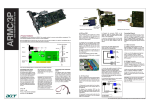
1
AOC-SIMSO/SIMSO+
SIMSO
User’s Guide
Revison 1.2a
AOC-SIMSO/SIMSO+ User’s Guide
The information in this User’s Manual has been carefully reviewed and is believed to be accurate. The
vendor assumes no responsibility for any inaccuracies that may be contained in this document, makes no
commitment to update or to keep current the information in this manual, or to notify any person or
organization of the updates. Please Note: For the most up-to-date version of this manual, please see
our web site at www.supermicro.com.
Super Micro Computer, Inc. (“Super micro”) reserves the right to make changes to the product described
in this manual at any time and without notice. This product, including software, if any, and documentation
may not, in whole or in part, be copied, photocopied, reproduced, translated or reduced to any medium or
machine without prior written consent.
IN NO EVENT WILL SUPERMICRO BE LIABLE FOR DIRECT, INDIRECT, SPECIAL, INCIDENTAL,
SPECULATIVE OR CONSEQUENTIAL DAMAGES ARISING FROM THE USE OR INABILITY TO USE
THIS PRODUCT OR DOCUMENTATION, EVEN IF ADVISED OF THE POSSIBILITY OF SUCH
DAMAGES. IN PARTICULAR, SUPERMICRO SHALL NOT HAVE LIABILITY FOR ANY HARDWARE,
SOFTWARE, OR DATA STORED OR USED WITH THE PRODUCT, INCLUDING THE COSTS OF
REPAIRING, REPLACING, INTEGRATING, INSTALLING OR RECOVERING SUCH HARDWARE,
SOFTWARE, OR DATA.
Any disputes arising between manufacturer and customer shall be governed by the laws of Santa Clara
County in the State of California, USA. The State of California, County of Santa Clara shall be the
exclusive venue for the resolution of any such disputes. Super Micro's total liability for all claims will not
exceed the price paid for the hardware product.
FCC Statement: This equipment has been tested and found to comply with the limits for a Class A digital
device pursuant to Part 15 of the FCC Rules. These limits are designed to provide reasonable protection
against harmful interference when the equipment is operated in a commercial environment. This
equipment generates, uses, and can radiate radio frequency energy and, if not installed and used in
accordance with the manufacturer’s instruction manual, may cause harmful interference with radio
communications. Operation of this equipment in a residential area is likely to cause harmful interference,
in which case you will be required to correct the interference at your own expense.
California Best Management Practices Regulations for Perchlorate Materials: This Perchlorate warning
applies only to products containing CR (Manganese Dioxide) Lithium coin cells. Perchlorate
Material-special handling may apply. See www.dtsc.ca.gov/hazardouswaste/perchlorate for further
details.
WARNING: HANDLING OF LEAD SOLDER MATERIALS USED IN THIS
PRODUCT MAY EXPOSE YOU TO LEAD, A CHEMICAL KNOWN TO THE
STATE OF CALIFORNIA TO CAUSE BIRTH DEFECTS AND OTHER
REPRODUCTIVE HARM.
Manual Revison 1.2a
Release Date: October 17, 2008
Unless you request and receive written permission from Super Micro Computer, Inc., you may not copy
any part of this document.
Information in this document is subject to change without notice. Other products and companies referred
to herein are trademarks or registered trademarks of their respective companies or mark holders.
Copyright © 2008 by Super Micro Computer, Inc.
All rights reserved.
Printed in the United States of America
ii
AOC-SIMSO/SIMSO+ User’s Guide
Table of Contents
Chapter 1 Introduction....................................................................... 1-1
1-1 Overview ............................................................................................. 1-1
1-2 1.2 IPMI Version 2.0 ......................................................................... 1-1
1-3 Product Features ............................................................................... 1-2
1-4 Checklist ............................................................................................. 1-2
1-5 Manual Images .................................................................................. 1-2
1-6 Contacting Supermicro ..................................................................... 1-3
1-7 Returning Merchandise for Service ................................................ 1-4
1-8 Safety Guidelines .............................................................................. 1-4
ESD Safety Guidelines ........................................................................... 1-4
General Safety Guidelines ...................................................................... 1-5
Chapter 2 Technical Specifications and
Hardware Installation.......................................................................... 2-1
2-1 Configuration and Card Connection ............................................... 2-1
2-2 Components and Layout .................................................................. 2-2
2-3 Connectors and Pin Definitions....................................................... 2-5
(J1) Mini Universal Serial Bus (USB) Connector .................................... 2-5
(JBT1) RISC CPU Reset......................................................................... 2-5
2-4 LED Descriptions and Pin Definitions ............................................ 2-6
(D1) Heartbeat LED Indicator ................................................................. 2-6
Dedicated LAN LED Indicators ............................................................... 2-6
2-5 Installing the AOC-SIMSO/SIMSO+ ............................................... 2-6
Chapter 3 Software Application and Usage ......................... 3-1
3-1 Configuring Addresses and Network Settings .............................. 3-1
3-2 Accessing the AOC-SIMSO/SIMSO+ Card .................................. 3-3
Log In Screen.......................................................................................... 3-4
Home Page Screen................................................................................. 3-5
3-3 Home Page Functions ...................................................................... 3-6
Remote Control....................................................................................... 3-7
KVM Console ....................................................................................... 3-7
SOL Console........................................................................................ 3-8
Remote Power ..................................................................................... 3-9
Virtual Media ......................................................................................... 3-10
iii
Table of Contents
Floppy Disk ........................................................................................ 3-10
CD-ROM Image ................................................................................. 3-12
Drive Redirection................................................................................ 3-14
Virtual Media Options......................................................................... 3-15
System Health....................................................................................... 3-17
Chassis Control.................................................................................. 3-17
Monitor Sensor................................................................................... 3-19
System Event Log .............................................................................. 3-21
Alert Settings...................................................................................... 3-22
User Management ................................................................................ 3-23
Change Password.............................................................................. 3-23
Users & Groups.................................................................................. 3-24
Permissions........................................................................................ 3-26
KVM Settings ........................................................................................ 3-27
User Console ..................................................................................... 3-27
Keyboard/Mouse ................................................................................ 3-30
Device Settings ..................................................................................... 3-31
Network .............................................................................................. 3-31
Dynamic DNS..................................................................................... 3-33
Security .............................................................................................. 3-35
Certificate ........................................................................................... 3-38
Date/Time........................................................................................... 3-40
Event Log ........................................................................................... 3-42
Maintenance ......................................................................................... 3-44
Device Information ............................................................................. 3-44
Event Log ........................................................................................... 3-45
Update Firmware................................................................................ 3-46
Unit Reset .......................................................................................... 3-47
3-4 Remote Console Screen Controls ................................................ 3-48
Drive Redirection Controls .................................................................... 3-49
Options Menu........................................................................................ 3-50
Chapter 4 Frequently Asked Questions.................................. 4-1
iv
Chapter 1
Introduction
This user's guide is written for system integrators, PC technicians and knowledgeable
PC users who intend to integrate Supermicro's unique IPMI 2.0 Management Utility with
support of KVM-over-LAN (*) into their systems. It provides detailed information for the
application and use of the AOC-SIMSO/SIMSO+ that supports remote access for
system monitoring, diagnosis and management. With the most advanced technologies
built-in, the AOC-SIMSO/SIMSO+ offers a complete, efficient, and cost-effective remote
server management.
NOTE: KVM-over-LAN is only for the AOC-SIMSO+ only.
1-1
Overview
The AOC-SIMSO/SIMSO+ is a highly efficient, highly compatible and easy-to-use IPMI
card. It allows you to take advantage of the BMC, a baseboard management controller
installed on a server motherboard, and the IPMIView, an IPMI compliant management
application software loaded in a PC, to provide serial links between the main processor
and other system components allowing network interfacing via remote access. With an
independent Raritan KIRA100 processor built-in, the AOC-SIMSO/SIMSO+ provides
you with a solution to work easier with complex and expensive systems. This card
allows an administrator to access, monitor and manage a server system by network
interfacing anywhere and anytime.
1-2
1.2 IPMI Version 2.0
The AOC-SIMSO/SIMSO+ supports the functionality of IPMI Version 2.0. Its key
features include the following:
•
Supports Serial over LAN
•
Supports KVM over LAN (For the AOC-SIMSO+ only)
•
Supports LAN Alerting-SNMP Trap
•
Supports Event Log
•
Offers OS (Operating System) Independency
•
Provides remote Hardware Health Monitoring via IPMI. Key features include the
following:
•
Temperature monitoring
•
Fan speed monitoring
•
Voltage monitoring
•
Power status monitoring, chassis intrusion monitoring
1-1
AOC-SIMSO/SIMSO+ User’s Guide
•
•
Remote power control to power-on, power-off or reboot a system
•
Remote access to text-based, graphic-based system information, including
BIOS configurations and OS operation information (KVM)
•
Remote management of utility/software applications
Provides Network Management Security via remote access/console redirection. Key
features include:
•
User authentication enhancement
•
Encryption support enhancement, allowing for password configuration security
to protect sensitive data transferring via Serial over LAN
•
Supports the following Management tools: IPMIView, CLI (Command Line Interface)
•
Supports RMCP & RMCP protocols
1-3
Product Features
The AOC-SIMSO/SIMSO+ Series (IPMI 2.0 with a Dedicated LAN) supports the
following product features:
•
Mini size (2.65" W x 1.75" H) (67.31 mm W x 44.45 mm H)
•
Supports IPMI over LAN
•
Supports 1U and above
•
Supports dedicated LAN
1-4
Checklist
If your shipping package came with missing or damaged parts, please contact
Supermicro's Technical Support. Please refer to the following checklist when contacting
us.
•
AOC-SIMSO/SIMSO+ Add-on Card
•
The SKT-0240L Kit: The SKT-0240L kit is included in the AOC-SIMSO+ shipping
package only. The SKT-0240L kit contains full-size and low profile I/O back plates, a
USB2RJ45 add-on card, and a CBL-0165L cable.
•
CDR-SIMIPMI: One Installation CD
•
White Box with Correct Barcode Label (showing AOC-SIMSO/SIMSO+).
1-5
Manual Images
The graphics shown in this user's guide were based on the latest PCB Revision
available at the time of publishing of this guide. The AOC-SIMSO/SIMSO+ card you’ve
received may or may not look exactly the same as the graphics shown in this user's
guide.
1-2
Chapter 1: Introduction
1-6
Contacting Supermicro
Headquarters
Address:
Super Micro Computer, Inc.
980 Rock Ave.
San Jose, CA 95131 U.S.A.
Tel:
+1 (408) 503-8000
Fax:
+1 (408) 503-8008
Email:
[email protected] (General Information)
[email protected] (Technical Support)
Web Site:
www.supermicro.com
Europe
Address:
Super Micro Computer B.V.
Het Sterrenbeeld 28, 5215 ML
‘s-Hertogenbosch, The Netherlands
Tel:
+31 (0) 73-6400390
Fax:
+31 (0) 73-6416525
Email:
[email protected] (General Information)
[email protected] (Technical Support)
[email protected] (Customer Support)
Asia-Pacific
Address:
Super Micro, Taiwan
4F, No. 232-1, Liancheng Rd.
Chung-Ho 235, Taipei County
Taiwan, R.O.C.
Tel:
+886-(2) 8226-3990
Fax:
+886-(2) 8226-3991
Web Site:
www.supermicro.com.tw
Technical Support:
Email:
[email protected]
Tel:
+886-2-8228-1366, ext. 132 or 139
1-3
AOC-SIMSO/SIMSO+ User’s Guide
1-7
Returning Merchandise for Service
A receipt or copy of your invoice marked with the date of purchase is required before
any warranty service will be rendered. You can obtain service by calling your vendor for
a Returned Merchandise Authorization (RMA) number. When returning to the
manufacturer, the RMA number should be prominently displayed on the outside of the
shipping carton, and mailed prepaid or hand-carried. Shipping and handling charges will
be applied for all orders that must be mailed when service is complete.
For faster service, RMA authorizations may be requested online at:
http://www. supermicro.com/support/rma/
Whenever possible, repack the chassis in the original Supermicro carton, using the
original packaging material. If these are no longer available, be sure to pack the chassis
securely, using packaging material to surround the chassis so that it does not shift within
the carton and become damaged during shipping.
This warranty only covers normal consumer use and does not cover damages incurred
in shipping or from failure due to the alteration, misuse, abuse or improper maintenance
of products.
During the warranty period, contact your distributor first for any product problems.
1-8
Safety Guidelines
WARNING: To avoid personal injury and property damage, please carefully
follow all the safety steps listed below when installing the AOC-SIMSO/SIMSO+
into your system.
ESD Safety Guidelines
Electro-Static Discharge (ESD) can damage electronic components. To prevent damage
to your system, it is important to handle it very carefully. The following measures are
generally sufficient to protect your equipment from ESD.
•
Use a grounded wrist strap designed to prevent static discharge.
•
Touch a grounded metal object before removing a component from the antistatic
bag.
•
Handle the add-on card by its edges only; do not touch its components, peripheral
chips, memory modules or gold contacts.
•
When handling chips or modules, avoid touching their pins.
•
Put the card and peripherals back into their antistatic bags when not in use.
1-4
Chapter 1: Introduction
General Safety Guidelines
•
Always disconnect power cables before installing or removing any components from
the computer.
•
Use only the correct type of bracket for the add-on card.
•
Disconnect the power cable before removing any cable from the add-on card.
•
Make sure that the SIMSO(+) add-on card is securely seated in the SIMSO slot to
prevent damage to the system due to power shortage. For SIMSO slot locations,
please refer to Section 2.4.2.
1-5
AOC-SIMSO/SIMSO+
Notes
1-6
Chapter 2
Technical Specifications and
Hardware Installation
2-1
Configuration and Card Connection
The AOC-SIMSO/SIMSO+ add-on card is connected to a dedicated LAN Ethernet port
located on the AOC-USB2RJ45 add-on card via an SMC proprietary cable (CBL-0165L)
for external LAN access. One end of the CBL-0165L cable is connected to the mini USB
connector (J1) located on the AOC-SIMSO/SIMSO+ card and the other end to that of
the AOC-USB2RJ45 card. There are two LEDs located on the LAN port to indicate
network links and activities. Refer to Figure 2-1 below for the configuration.
Figure 2-1. SKT-0240L Kit
Mini USB Connector (J1)
AOC-SIMSO/SIMSO+
Mini USB Connector (J1)
Dedicated
Ethernet
(LAN) Port
CBL-0165L Cable, or
CBL-0177L Long Cable
(See Note below)
AOC-USB2RJ45
LAN LEDs
2-1
AOC-SIMSO/SIMSO+ User’s Guide
When the two cards are connected, the AOC-SIMSO/SIMSO+ card detects the
AOC-USB2RJ45 card’s existence every time after AC power-on. When connected, the
AOC-SIMSO/SIMSO+ uses dedicated LAN as the network interface. If not connected to
the AOC-USB2RJ45 card, the AOC-SIMSO/SIMSO+ card instead uses the
Motherboard LAN1 as its network interface.
For dedicated LAN to work properly, the CBL-177L long cable is required for a
motherboard with a SIMSO IPMI module that is located far from the back plate of the
chassis. Refer to the motherboard specifications on our web site to determine if you
need this cable.
The CBL-177L cable is purchased separately from Supermicro or with the SKT-0240L
kit. The SKT-0240L kit contains full-size and low profile I/O back plates, a USB 2RJ45
add-on card, and a CBL-0165L cable. The SKT-0240L kit is included in the SIMSO+
shipping package only.
NOTE: You can also use LAN1 on the motherboard if you do not need the
dedicated LAN support. However, dedicated LAN is recommended for better
graphic support when the KVM feature is used.
2-2
Components and Layout
The AOC-SIMSO/SIMSO+ add-on card’s components are shown in the front
(Figure 2-2) and rear (Figure 2-3) layout diagrams below, and are listed and described
in Table 2-1.
2-2
Chapter 2: Technical Specifications and Hardware Installation
Figure 2-2. AOC-SIMSO/SIMSO+ Front View Layout
SIMSO
5
6
7
3
1
4
2
Figure 2-3. AOC-SIMSO/SIMSO+ Rear View Layout
9
10
8
2-3
AOC-SIMSO/SIMSO+ User’s Guide
Table 2-1. AOC-SIMSO/SIMSO+ Components
Item
Description
1
Raritan's Kira 100 RISC System on Chip
2
Firmware with Linux System & Boot ROM
3
Transformer
4
SDRAM (128Mb/133MHz)
5
J1 Mini USB 9-pin Connector
6
JBT1 Kira 100 Processor Reset
7
D1 Heartbeat Activity LED Indicator
8
SDRAM (128Mb/133MHz)
9
V-SDRAM (128Mb/166MHz) (AOC-SIMSO+ only)
10
PHY
The block diagram for the card is shown in Figure 2-4.
Figure 2-4. AOC-SIMSO/SIMSO+Block Diagram
25MHz Magnetics
PHY
8-pin
cable
RJ45
50MHz
MAC
10/100
5 Channel I2C
Flash
MEM
LPC Interface
4Mx16
KIRA100
ARM RISC CPU SYSTEM
FML Interface
2Mx32
SMC Proprietary GPIO
3.3V
1.8V
100 Mhz
DVO Video Interface
V-SDRAM
8Mx16
RMII Interface
DMA/MC
SIMSO
200-pin So DIMM Socket
USB Interface
UART Interface
RTC/PMU WDT/Timer
32.768KHz
2-4
12.288MHz
SDRAM
Chapter 2: Technical Specifications and Hardware Installation
2-3
Connectors and Pin Definitions
Connectors and pin definitions for the AOC-SIMSO/SIMSO+ add-on card are described
below.
(J1) Mini Universal Serial Bus (USB) Connector
There is a mini USB connector (J1) located on the AOC-SIMSO/SIMSO+ and another
mini USB connector is located on the AOC-USB2RJ45 card. Use Cable CBL-0165L or
CBL-0177L to connect the two mini USB connectors on both add-on cards for external
LAN access. Refer to page 2-1 for other details. See Table 2-2 below for pin definitions.
Table 2-2. Mini USB Pin Definitions (J1)
Pin
Definition
1
Eth-TX_H
2
Eth-TX_L
3
Phy-100
4
Eth-RX_L
5
Eth-RX_H
6
Phy-ACT
7
Dedicated LAN Detected
8
3V-duall
9
Ground
(JBT1) RISC CPU Reset
JBT1 is used to reset the Kira 100 Processor, NIC, UART, USB and R.T. Instead of pins,
this jumper consists of contact pads to prevent the accidental reset.
Use a metal object such as a small screwdriver to touch both pads at the same time to
short the connection. After a reset or AC power-on, the AOC-SIMSO/SIMSO+ card will
automatically detect if a CBL-0165L cable is connected.
If a cable is not detected, the AOC-SIMSO/SIMSO+ will transfer the Remote Control
Function to LAN1 on the motherboard.
If a cable is detected, the AOC-SIMSO/SIMSO+ will use the dedicated LAN on the card
to manage motherboard activities via Remote Console.
2-5
AOC-SIMSO/SIMSO+ User’s Guide
2-4
LED Descriptions and Pin Definitions
LED Descriptions and pin definitions for the AOC-SIMSO/SIMSO+ add-on card are
described below.
(D1) Heartbeat LED Indicator
Heartbeat LED (D1), located on the front side of the AOC-SIMSO/SIMSO+card,
indicates the functionality and activity of the add-on card. The blinking of the Heartbeat
LED indicates that the AOC-SIMSO/SIMSO+ is active. However, when the Linux OS
and the drivers are being loaded after each AC power-on or reset, the Heartbeat LED is
off for about a minute. Then, the Heartbeat LED will be on again to indicate that the
AOC-SIMSO/SIMSO+ is active. See Table 2-3 below for details.
Table 2-3. Heartbeat LED (D1)
State
Description
On (Blinking)
AOC-SIMSO/SIMSO+ active
Off (for 1 minute)
Loading Firmware
Off (Continuously)
SIMSO is not active
Dedicated LAN LED Indicators
Link/Activity LED
Speed LED
There are two LAN LED Indicators located on the (Dedicated) LAN port on the
AOCUSB2RJ45 Add-On Card. The green LED indicates link status, while the amber
LED may be on or off to indicate the speed of the Ethernet connection. See Table 2-4
below for more information.
Table 2-4. Dedicated LAN LED Indicators
2-5
Link/Activity LED (Amber)
Speed LED (Green)
State
Description
State
Description
Flashing
Active
Steady On
Link Status
Off
Inactive
Off
No Connection or 10 Mbps
Installing the AOC-SIMSO/SIMSO+
The AOC-SIMSO/SIMSO+ add-on card installs into a SIMSO slot on a motherboard. To
properly use the AOC-SIMSO(+), be sure to install it in the right slot. Refer to the
motherboard layout below for an example of a SIMSO slot location on a motherboard.
2-6
Chapter 2: Technical Specifications and Hardware Installation
SIMSO Slot
2-7
AOC-SIMSO/SIMSO+
Notes
2-8
Chapter 3
Software Application and Usage
With an independent I/O processor embedded in Raritan's Kira 100 RISC System Chip,
the AOC-SIMSO/SIMSO+ add-on card allows you to access, monitor, manage and
interface with systems that are in remote locations via LAN. The necessary utilities for
the access and configuration of the add-on card are included on the Supermicro boot
CDs that came with your card.
This section provides information on the configuration and the access of the IPMI card
on the network.
3-1
Configuring Addresses and Network Settings
To use either the IPMICFG utility or the Windows utility to configure IP/MAC Addresses
and other IPMI network settings.
Configuring using the IPMICFG Utility:
1. Run the IPMICFG utility from the boot CD that came with your shipment.
2. Refer to Table 3-1 below to configure the IP/MAC addresses:
Table 3-1. IPMI MAC Address Configuration
Communication
Through
Board
IPMI
MAC
IP
X7 Series with LAN
82563EB, 82575EB
IPMI Card
Available IP/
DHCP(default)
Dedicated LAN
SIMSO(+)
SIMSO(+)
Available IP/
DHCP(default)
Dedicated LAN
H8 DDR2 Memory
Available IP/
DHCP(default)
Dedicated LAN
H8QM8/E-x
SIMSO(+)
X7 Series with LAN
82573
IPMI Card
IPMI Card
IPMI Card
SIMSO(+)
LAN1
Available IP/
DHCP(default)
LAN1 on MB
LAN1 on MB
LAN1 on MB
Dedicated LAN
LAN1 on MB
3. Follow the instructions given in the Readme.txt file to configure Gateway
IP/Netmask IP addresses, to enable/disable DHCP and to configure other IPMI
settings.
NOTE: FW R1.59 and higher will have "fail over" function, meaning FW will
search for DHCP after start-up. If DHCP does not exists, FW will use static IP.
3-1
AOC-SIMSO/SIMSO+ User’s Guide
NOTE: It is recommended that if you have to use on-board LAN, then you must
use a dedicated LAN for motherboards with the Intel NIC 82573 chip. You must
must also configure IPMI MAC address the same as the MAC address of the
Intel NIC 82573 LAN1.
Also beware that:
•
The speed will be very slow, and
•
You cannot ping the static IP when it is different than that of the
on-board Intel NIC 82573 chip. In this case you can only see or use the
IPMI when using the IPMIView utility.
NOTE: The Readme.txt file is included in the CD that came with your shipment.
A copy of the Readme.txt file, dated 07/11/2008, is also included below.
IPMICFG Version 1.10 (Build 080711) Copyright 2008 SuperMicro
Computer Inc.
Usage: IPMICFG params (Example: IPMICFG -m 192.168.1.123)
-m
Show IP and MAC
-m IP
Set IP (format: ###.###.###.###)
-a MAC
Set MAC (format: ##:##:##:##:##:##)
-k
Show Subnet Mask
-k Mask
Set Subnet Mask (format: ###.###.###.###)
-dhcp
Get the DHCP status
-dhcp on
Enable the DHCP
-dhcp off
Disable the DHCP
-g
Show Gateway IP
-g IP
Set Gateway IP (format: ###.###.###.###)
-r
BMC cold reset
-garp on
Enable the Gratuitous ARP
-garp off
Disable the Gratuitous ARP
-fd
Reset to the factory default
-ver
Get Firmware revision
-vlan
Get VLAN status
-vlan on [VLANtag] Enable the VLAN and set the VLAN tag
If VLANtag is not given it uses previously
saved value.
-vlan off
Disable the VLAN
-raw
Send a RAW IPMI request and print response.
Format: NetFn LUN Cmd [Data1 ... DataN]
3-2
Chapter 3: Software Application and Usage
Configuring using the Windows Utility:
1. Start the Supermicro IPMI Configuration Utility. This brings up the IPMI
CONFIGURATION UTILITY screen (Figure 3-1).
Figure 3-1. IPMI Configuration Utility Screen
2. Refer to Table 3-1 for IPMI MAC addresses and fill out all information in the IPMI
CONFIGURATION UTILITY screen. Press SET to configure using the settings you
entered.
3-2
Accessing the AOC-SIMSO/SIMSO+ Card
Use the procedures below for accessing the SIMSO card.
Using the Onboard LAN1 Connection:
1. Choose a computer that is connected to the same network and open the IPMIView
utility.
2. Go to FILE J NEW J SYSTEM. Type the SYSTEM NAME, IP ADDRESS OF LAN1 and
DESCRIPTION in the appropriate blanks and press the ENTER key.
3. Select the system from the IPMI DOMAIN. Type the LOGIN ID and PASSWORD in the
appropriate blanks to log into the IPMIView utility’s LOGIN screen.
NOTE: For information on the IPMIView utility, refer to the IPMI View User’s
Guide. This user’s guide may be obtained from the Super Micro website and
our Supermicro FTP website (SUPPORT J SUPPORT HOME J SUPERMICRO FTP
WEBSITE).
3-3
AOC-SIMSO/SIMSO+ User’s Guide
Using the Dedicated LAN:
1. Choose a computer that is connected to the same network and open the browser.
2. Type in the IP address of each server that you want to connect to in the address bar
in your browser.
3. Once the connection is made, the LOGIN screen (Figure 3-2) for the web-based IPMI
utility, as shown below, displays.
NOTE: You may also use the IPMIView utility instead of the web-based IPMI
utility. See the IPMIView User’s guide for a description on this application’s use.
Log In Screen
Once you are connected to the remote server, the following LOGIN screen displays
(Figure 3-2).
Figure 3-2. Login Screen
3-4
Chapter 3: Software Application and Usage
Logging In to the IPMICFG Utility using the Login Screen:
1. Type in your Username in the USERNAME box.
2. Type in your Password in the PASSWORD box and click on the LOGIN button.
NOTE: The default username is ADMIN. The default password is ADMIN.
The HOME PAGE screen (Figure 3-3) appears.
Home Page Screen
The HOME PAGE screen (Figure 3-3) appears after login. Table 3-2 lists and describes its
components.
Figure 3-3. Home Page Screen
1
2
4
3
9
5
6
7
3-5
8
AOC-SIMSO/SIMSO+ User’s Guide
Table 3-2. Home Page Screen Components
Item
Name
Description
1
Home Icon
Click this icon to return to the HOME PAGE screen.
2
Console Icon
Click this icon to go to the REMOTE CONSOLE screen.
3
Remote Console
Screen
Displayed in the window is the REMOTE CONSOLE screen. Click on
this window to go to the REMOTE CONSOLE screen.
4
Logout Icon
Click on this icon to log out of the system. This will display the LOGIN
screen again (Figure 3-2).
5
Refresh Button
Click on this icon to refresh the screen of the remote console
preview.
6
Power On Button
Click on this button to power on the system of the remote host.
7
Power Down Button
Click on this button to power down the system of the remote host.
8
Reset Button
Click on this button to reset the remote host.
9
Home Page Menu
Click on these buttons to display and use their sub-menu functions
as specified in Table 3-3.
3-3
Home Page Functions
Table 3-3 contains a brief summary of HOME PAGE menu. The sub-menu functions of
this menu are further detailed in following sections.
Table 3-3. Home Page Menus
Function Key
Description
Remote Control
Click on this icon for remote access and management of Video Console
Redirection. See "Remote Control" below for further details.
Virtual Mediaa
Click on this icon to use virtual remote media devices. See "Virtual Media" below
for further details.
System Health
Click on this icon to view and manage health monitoring for remote systems. See
"System Health" below for further details.
User Management
Click on this icon for User Management. See "User Management" for further
details.
KVM Settings1
Click on this icon to configure keyboard, Video and mouse settings. See "KVM
Settings" below for further details.
Device Settings
Click on this icon to configure device settings. See "Device Settings" below for
further details.
Maintenance
Click on this icon to access, diagnose and manage hardware devices. See
"Maintenance" below for further details.
a. For large data transfers like KVM and Virtual Media, dedicated LAN (100Mb/sec) should
be used. The on-board LAN (through I2C interface, 100Kb/sec) is too slow.
3-6
Chapter 3: Software Application and Usage
Remote Control
Click on the REMOTE CONTROL button to activate the KVM Console, SOL Console and
Remote Power menu options.
KVM Console
Clicking on this menu option brings up the REMOTE CONSOLE screen (Figure 3-4) for
configuring settings for the remote host. See Table 3-4 for a list and description of major
controls and features of this console screen.
Figure 3-4. Remote Console Screen
4
5
1
2
3
Table 3-4. Remote Console Screen Controls and Features
Item
Name
Description
1
Mouse Cursor
The mouse cursor changes to reflect either Single/Synchronized
Mouse Mode or Double Mouse Mode.
In the Single/Synchronized Mouse Mode, this cursor indicates the
system that is currently active. For the Double Mouse mode, this is
the cursor for the remote host.
2
This icon indicates the number of networks (users) that are
Network Number Icon connected via Console Redirection. (The number of figure icons
indicates the number of users connected.)
3
Keyboard/Mouse Icon This icon indicates the availability of the Keyboard and Mouse.
3-7
AOC-SIMSO/SIMSO+ User’s Guide
Table 3-4. Remote Console Screen Controls and Features (Continued)
Item
Name
Description
4
Drive Redirect Icon
Click on this icon to expand out the controls for drive redirection on
the system you are viewing. See "Drive Redirection Controls" for
further details.
5
Options Button
Click on this button to see the REMOTE CONSOLE OPTIONS menu. See
"Options Menu" for further details on this menu.
SOL Console
Click on this menu option to bring up the Serial over LAN (SOL) remote console.
Figure 3-5. SOL Console Screen
1
2
3
4
5
6
Table 3-5. SOL Console Screen Controls and Features
Item
Name
Description
1
Baud Rate
Use this drop-down list box to set the Baud rate for the SOL Console
to use.
2
Start Button
Click this button to start data download to the SOL CONSOLE screen.
3
Stop Button
Click this button to stop data download to the SOL CONSOLE screen.
3-8
Chapter 3: Software Application and Usage
Table 3-5. SOL Console Screen Controls and Features (Continued)
Item
Name
Description
4
Power On Button
Click on this button to power on the system of the remote host.
5
Power Down Button
Click on this button to power down the system of the remote host.
6
Reset Button
Click on this button to reset the remote host.
Remote Power
Click on this menu option to bring up the REMOTE POWER screen (Figure 3-6) for
configuring the power settings for the Remote Console. See Table 3-6 for a list and
description of major controls in this screen.
Figure 3-6. Remote Power Screen
1
2
3
Table 3-6. Remote Power Screen Controls
Item
Name
Description
1
Power On Button
Click on this button to power on the remote host.
2
Power Down Button
Click on this button to power down the remote host.
3
Reset Button
Click on this button to reset the remote host.
3-9
AOC-SIMSO/SIMSO+ User’s Guide
Virtual Media
Click on the VIRTUAL MEDIA button to display the Floppy Disk, CD-ROM Image, Drive
Redirection and Virtual Media Options menu options.
Floppy Disk
Click on this menu option to bring up the FLOPPY DISK screen (Figure 3-7). See
Table 3-7 for a list and description of controls in this screen.
Figure 3-7. Floppy Disk Screen
1
2
3
4
5
6
Table 3-7. Floppy Disk Screen Controls
Item
Name
Description
1
Active Image (Drive1)
This section displays the data that has been uploaded to Drive 1 of
the remote host.
2
Active Image (Drive2)
This section displays the data that has been uploaded to Drive 2 of
the remote host.
3-10
Chapter 3: Software Application and Usage
Table 3-7. Floppy Disk Screen Controls (Continued)
Item
Name
3
This section allows you to upload the floppy image as FLOPPY located
in the remote host. The floppy image uploaded is in the binary format
Floppy Image Upload
with a maximum size of 1.44MB. It will be loaded to the Supermicro
SIMSO card and will be emulated to the host as a USB device.
Description
4
Virtual Drive
Drop-down List Box
Use this drop-down list to select a drive in the remote host as a
destination drive for your image data upload.
5
Floppy Image File
Click on BROWSE to preview and select the files that you wish to
upload to the host drive selected in Item 4 above.
6
Upload Button
Once the correct file name appears in the box for the FLOPPY IMAGE
FILE, click UPLOAD to upload the floppy image to the drive specified in
the remote host you selected using the VIRTUAL DRIVE drop-down list
(Item 4).
3-11
AOC-SIMSO/SIMSO+ User’s Guide
CD-ROM Image
Click on this menu option to share data stored in your local CD-ROM drive with other
users in the remote host through the Windows Share application via USB, and to bring
up the CD-ROM screen (Figure 3-8). See Table 3-8 for a list and description of controls
in this screen.
Figure 3-8. CD-ROM Image Screen
1
2
3
4
5
6
7
8
9
Table 3-8. CD-ROM Image Screen Controls
Item
Name
1
This window displays the file name of the data currently active in host
Active Image (Drive1)
Drive 1.
Description
2
Active Image (Drive2)
This window displays the file name of the data currently active in host
Drive 2.
3
Image on Windows
Share
This option allows the user to configure Windows Share settings. It
allows you to decide how you want to share the data stored in your
local CDROM with users in the remote host.
4
Virtual Drive
Specify the drive that you want to share your data with in the remote
host.
3-12
Chapter 3: Software Application and Usage
Table 3-8. CD-ROM Image Screen Controls (Continued)
Item
Name
Description
5
Share Host
Key in the IP Address or the name of the system you wish to share
data with via Windows Share.
6
Share Name
Key in the name of the system you wish to share data with in the
remote host.
7
Path to Image
Key in the location of source files that you wish to share via Windows
Share.
User/Password
(Optional)
Key in the USERNAME and PASSWORD for the person to access the
data that you want to share and click the SET button to enter your
selections.
8
9
3-13
AOC-SIMSO/SIMSO+ User’s Guide
Drive Redirection
Click on this menu option to make local drives accessible for other users via console
redirection, and brings up the DRIVE REDIRECTION screen (Figure 3-9). See Table 3-9 for
a list and description of controls in this screen.
This function allows you to share your local drives (Floppy, CD-ROM and HDDs) with
users in the remote systems.
Figure 3-9. Driver Redirection Screen
1
2
3
5
6
7
8
Table 3-9. Driver Redirection Screen Controls
Item
Name
1
This window displays the file name of the data currently active in host
Active Image (Drive1)
Drive 1.
2
Active Image (Drive2)
3
Drive Redirection
Use this window to configure Drive Redirection settings.
Disable Drive
Redirection
Check the box to disable Drive Redirection. Once this function is
disabled, local drives will not be accessible for other users in remote
host.
4
Description
This window displays the file name of the data currently active in host
Drive 2.
3-14
Chapter 3: Software Application and Usage
Table 3-9. Driver Redirection Screen Controls (Continued)
Item
Name
Description
5
Force Read Only
Check this box to allow the data stored in local drives to be read in a
remote system, but it cannot be overwritten to ensure data integrity
and system security.
6
Apply Button
Once you've configured your settings, click the APPLY button to enter
your settings.
7
Reset Default button
You can key in your own setting values and reset these values as
"default" by clicking on this button to reset the defaults.
Virtual Media Options
Click on this menu option to bring up the VIRTUAL MEDIA OPTIONS screen (Figure 3-10).
See Table 3-10 for a list and description of controls in this screen.
Figure 3-10. Virtual Media Options Screen
1
2
3
3-15
AOC-SIMSO/SIMSO+ User’s Guide
Table 3-10. Virtual Media Options Screen Controls
Item
Name
1
Use this option to disable or enable USB MASS storage in the
remote host. Check this box to disable the function of VIRTUAL MEDIA
Virtual Media Options
OPTIONS to prevent data stored in a local drive from being accessed,
Check Box
or uploaded by the user in the remote host. The default setting is
"enabled" (checked).
Description
2
Apply Button
Once you've checked the VIRTUAL MEDIA Options check box, click
APPLY to enter this value.
3
Reset to Defaults
Button
If you want to set DISABLED as the default setting for VIRTUAL MEDIA
OPTIONS, click on this button.
3-16
Chapter 3: Software Application and Usage
System Health
Click on the SYSTEM HEALTH button to display the Chassis Control, Monitor Sensor,
System Event Log and Alert Settings menu options.
Chassis Control
Click on this menu option to bring up the CHASSIS CONTROL screen (Figure 3-11). See
Table 3-11 for a list and description of controls in this screen.
Figure 3-11. Chassis Control Screen
1
2
3-17
AOC-SIMSO/SIMSO+ User’s Guide
Table 3-11. Chassis Control Screen Controls
Item
1
2
Name
Description
Chassis Information
The following remote chassis information are included:
• Power Is: This indicates if the system is on or off for the remote
host.
• Power On Counter: If power is on, then the counter indicates the
length of time the power has been turned on.
• Last Restart Cause: This item states the reason why the host
system is restarted if the system has been turned off.
• Refresh: Click the REFRESH button to update the information in
the CHASSIS INFORMATION section above.
Power Control
The following Power Control items are included:
• Power On: Click on this button to power on the system for the
remote host.
• Power Down: Click on this button to power down the system for
the remote host.
• Power Cycle: Click on this button to power down the system for
the remote host and turn it back on later.
• Reset: Click on this button to reset the remote console.
3-18
Chapter 3: Software Application and Usage
Monitor Sensor
Click on this menu option to bring up the MONITOR SENSOR screen (Figure 3-12). This
screen displays a table with health monitoring information. See Table 3-12 for details on
this table’s information. Clicking the Refresh button refreshes the data in the screen.
Figure 3-12. Monitor Sensor Screen
Table 3-12. Monitoring Sensors Table
Sensor Type
Temperature Monitoring
Sensor Name
Description
CPU1 Temperature (Temp A,
Temp B)
Temp A: CPU1 Core1 Temperature,
Temp B: CPU1 Core2 Temperature,
CPU2 Temperature (Temp A,
Temp B)
Temp A: CPU2 Core1 Temperature,
Temp B: CPU2 Core2 Temperature,
System Temperature
3-19
AOC-SIMSO/SIMSO+ User’s Guide
Table 3-12. Monitoring Sensors Table (Continued)
Sensor Type
Sensor Name
Description
CPU1 VCore
CPU1 Vcore: CPU1 Core Voltage
CPU2 VCore
CPU2 Vcore: CPU2 Core Voltage
3.3V
Voltage Monitoring
5V, 5VSB
5VSB: 5V Standby
+12V, -12V
1.5V
Fan Control
Physical Security
VBAT
VBAT: Battery Voltage
Fan1/CPU Fan
CPU Fan
Fan2/CPU Fan
CPU Fan
Fan 3 – Fan 6
System Fans/Chassis Fans
Chassis Intrusion
Monitors chassis intrusion
Power Supply
There is a 5-pin connector (PWRI2C)
on the motherboard for the power
supply (if it supports power I2C and
power fail detect functions). The IPMI
will monitor the power failure status.
Module/Board CPU0
Internal E.
Internal Error reported from CPU0. If
Quad CPU motherboard is used, that
means one of the CPUs has an error.
Module/Board CPU1
Internal E.
Internal Error reported from CPU1, if
Dual CPU motherboard is used.
Module/Board CPU
Overheat
When the CPU temperature exceeds
this preset temperature, the overheat
LED or alert will be triggered, the CPUs
will slow down, the CPU fans will be in
the full speed mode.
Module/Board Thermal Trip
There is thermal sensor in CPU that is
triggered when temperature is too high.
When this sensor is triggered, the CPU
will shut itself down automatically to
prevent damage. IPMI monitors this
signal and logs the status in the event
log.
3-20
Chapter 3: Software Application and Usage
System Event Log
Click on this menu option to bring up the SYSTEM EVENT LOG screen (Figure 3-13). This
screen displays the System Health Event Log for the remote host system. See
Table 3-13 for details on this screen’s controls and features.
Figure 3-13. System Event Log Screen
1
2
3
Table 3-13. System Event Log Screen Controls and Features
Item
Name
Description
1
System Event Log
This table lists system event log information in order of its latest
appearance.
2
Clear Button
Clicking this button clears information from the System Event Log.
3
Refresh Button
Clicking this button refreshes the data on the screen.
3-21
AOC-SIMSO/SIMSO+ User’s Guide
Alert Settings
Click on this menu option to bring up the ALERT SETTINGS screen (Figure 3-14), which
displays alert settings for the remote host system. The items monitored include a FILTER
LIST, a POLICY LIST and a LAN DESTINATION LIST. Clicking on the heading for each of
these lists displays only that display list on the screen.
Figure 3-14. Alert Settings Screen
3-22
Chapter 3: Software Application and Usage
User Management
Click on the USER MANAGEMENT button to display the Change Password, Users &
Groups and Permissions menu options.
Change Password
Click on this menu option to bring up the CHANGE PASSWORD screen (Figure 3-15). See
Table 3-14 for a list and description of controls in this screen.
Figure 3-15. Change Password Screen
1
2
Table 3-14. Change Password Screen Controls
Item
Name
1
New Password Field
Description
Key in your new password in the field.
2
Confirm New
Password Field
Key in your new password in the field again and click the APPLY
button to confirm it.
3-23
AOC-SIMSO/SIMSO+ User’s Guide
Users & Groups
Click on this menu option to bring up the USERS & GROUPS screen (Figure 3-16). See
Table 3-15 for a list and description of controls in this screen.
Figure 3-16. Users & Groups Screen
1
2
3
4
5
6
7
8
10
11
12
9
13
14
15
16
17
16
17
18
19
20
14
15
Table 3-15. Users & Groups Screen Controls
Item
Name
Description
1
User Management
This window displays the user's information.
2
Existing Users
Select an existing user for information updates. Once a user is
selected, click on the LOOKUP button on right to view user
information.
3
New User Name
Enter a new user name in this field.
4
Full User Name
Enter a full user name in this field.
5
Password
6
Confirm Password
Type the user's password in the field and then type the password
again in the next field to confirm it. The password must be four (4)
characters or longer in length.
7
Email Address
(Optional) Enter the user's email address in the field.
8
Mobile Phone
(Optional) Enter the user's mobile phone number in the field.
3-24
Chapter 3: Software Application and Usage
Table 3-15. Users & Groups Screen Controls (Continued)
Item
Name
Description
9 –12
Group Membership
This section allows you to enter Group Membership information. The
GROUP MEMBERSHIP field (Item 9) indicates the group that the user
belongs to. To select a group:
1. Click on the group name on the NOT MEMBER OF pane
(Item 10) to select it.
2. Click on the backwards arrow (Item 11) to enter the group
name in the GROUP MEMBERSHIP field (Item 9).
3. Reverse the procedure using the forwards arrow (Item 12) to
remove the user from a group.
13
IPMI Privilege Level
Click on the arrow key on the right to activate the PRIVILEGE
SELECTION menu. The IPMI PRIVILEGE LEVEL contains five
categories: NO ACCESS, USER, OPERATOR, ADMINISTRATOR and OEM.
14
Create
Click on this button to enter a new user's or group information in the
USER/GROUP MANAGEMENT fields.
15
Modify
Click on this button to modify a user's or group information in the
USER/GROUP MANAGEMENT fields.
16
Copy
Click on this button to copy a user's or group information in the USER/
GROUP MANAGEMENT fields.
Copy User
1. Choose an EXISTING USER from the selection box.
2. Enter a new user name in the NEW USER NAME field.
3. Click on the COPY button and a new user with the name you
have entered will be created.
The properties of the selected user will be copied to the new user.
Copy Group
1. Choose an EXISTING group from the selection box.
2. Enter a new group name in the NEW GROUP NAME field.\
3. Click on the COPY button and a new group with the name
you've typed in will be created.
The properties of the selected group will be copied to the new
group.
17
Delete
Click on this button to delete a user's or group information in the
User/Group Management fields.
Group Management
This section allows you to either select, modify, copy, delete or create
a group for better user management. You can either select a group
from the EXISTING GROUPS drop-down list box (Item 19), or you can
create a group by entering a name in the NEW GROUP NAME field
(Item 20) and then pressing the CREATE button.
Groups can be deleted, copied or modified by selecting them from
the EXISTING GROUPS drop-down list box (Item 19) and clicking on
the DELETE, COPY or MODIFY buttons respectively.
18 – 20
3-25
AOC-SIMSO/SIMSO+ User’s Guide
Permissions
Click on this menu option to bring up the PERMISSIONS screen (Figure 3-17). See
Table 3-16 for a list and description of controls in this screen.
Figure 3-17. Permissions Screen
1
3
2
5
4
Table 3-16. Permissions Screen Controls
Item
Name
1
Show Permissions for Use this drop-down list box to select your user/group permissions
User/Group
selection.
Description
2
Update Button
3
Effective Permissions This table column indicates the actual permissions a user/group has.
Click this button to update permissions information to correspond to
the selection you made in the SHOW PERMISSIONS FOR USER/GROUP
drop-down list box.
4
User Permissions
This table column indicates the actual permissions a user has.
5
Inherited Group
Permissions
This table column indicates the permissions a user has due to the
fact that he or she belongs to a certain group.
3-26
Chapter 3: Software Application and Usage
KVM Settings
Click on the KVM SETTINGS button to display the User Console and Keyboard/Mouse
menu options.
User Console
Click on this menu option to bring up the USER CONSOLE screen (Figure 3-18). See
Table 3-17 for a list and description of controls in this screen.
Figure 3-18. User Console Screen
1
2
3
4
5
6
7
8
9
10
11
12
13
14
15
16
17
18
19
20
21
22
23
3-27
AOC-SIMSO/SIMSO+ User’s Guide
Table 3-17. User Console Screen Controls
Item
Name
Description
1
User Selection Field
This drop-down list box allows you to select which group the user
belongs to.
2
Update Button
Once you've selected the group name, click on the UPDATE button to
save the selections.
3
Transmission
Encoding
This section allows you to decide how (the video) data is transmitted
between the local system and the remote host.
NOTE: You can only select one item from Item 4, 5 and 7.
4
Automatic Detection
Select this option to allow the OS to automatically detect the
networking configuration settings such as the bandwidth of the
connection line, and transmit data accordingly.
5
Pre-configured
This option allows you to select the data transmission setting from a
pre-defined options list. The pre-configured settings will provide the
best result because the compression and color depth settings will be
adjusted for optimization based on the network speed indicated.
6
Network speed
Once you've selected the pre-configured option above, you then can
select a desired network speed setting from this drop-down list box.
7
Manually
You can select a desired network speed setting using this option.
This allows you to adjust both Compression (Item 8) and Color Depth
(Item 9) settings individually.
8
Compression
This drop-down list box is used to specify data compression. Data
signal transmission is compressed to save bandwidth. High
compression rates will slow down network interfacing, so you can not
not use these when several users are connected to the network.
9
Color Depth
This drop-down list box is used to select either 16-bit high colors or
8-bit 256-colors. The standard color depth is 16-bit high color, and is
recommended for compression level 0. For typical desktop
interfaces, the setting of 8-bit 256-colors is recommended for faster
data transmission.
10
Remote Console
Type
This section allows you to decide which Remote Console Viewer to
use.
11
Default Java VM
(JVM)
Select this option to use the default Java Virtual Machine of your web
browser. This can be the Microsoft JVM or the Sun JVM, depending
on the configuration of your browser.
12
Sun Microsystems
Java Browser Plugin
Select this option when the JVM used to run the code for the Remote
Console is a Java Applet. If you use this function for the first time and
the appropriate Java plugin is not yet installed in your system, you
may download and install it automatically. To download and install it,
you need to check YES in the dialogs. Downloading Sun's JVM will
allow you to use a stable and identical JVM across different
platforms.
NOTE: If your internet connection is slow, please pre-install the JVM
on your administration machine.
13
Miscellaneous
Remote Console
Settings
This section allows you to specify some other Remote Console
settings.
3-28
Chapter 3: Software Application and Usage
Table 3-17. User Console Screen Controls (Continued)
Item
Name
Description
14
Check this box to enable the Start in Monitor Mode, which allows
data to be displayed in the remote monitor as soon as the Remote
Start in Monitor Mode Console is activated.
NOTE: The data displayed in the remote monitor is ready-only.
15
Start in Exclusive
Access Mode
Check this box to enable the Exclusive Access Mode immediately at
Remote Console startup. This forces all other users connected to the
network to close, and no other users can open the Remote Console
until you disable this function or log off.
16
Mouse Hotkey
This section allows you to configure a hot key combination for mouse
mode.
17
Hotkey
This drop-down list box allows you to use a hot key combination to
specify either Mouse Synchronization Mode or Single Mouse Mode.
18
Remote Console
Button Keys
This section allows you to define button keys for the remote host.
The button keys allow simulating keystrokes on a remote host or
issuing commands to a remote system. These button keys are
needed when you have a missing key or when you want to prevent
interference to the local system. After a remote console button key is
set, it will appear on the right upper corner of the remote monitor
screen.
NOTE: For details instructions in creating button keys, please click
on the link – Click here for Help.
19
Button Keys
Enter the syntax of a button key in the field provided.
NOTE: For detailed instructions in creating button keys, please click
on the link – Click here for Help.
20
Name
Key in the name of a button key in the field provided.
NOTE: For details instructions in creating button keys, please click
on the link – Click here for Help.
21
More Entries Button
Click on this button to create more Button Keys.
22
Apply Button
When you have made all your changes to this screen, click the
APPLY button to apply all your changes to the system.
23
Reset to Defaults
Button
Click this button to restore all default settings to the screen.
3-29
AOC-SIMSO/SIMSO+ User’s Guide
Keyboard/Mouse
Click on this menu option to bring up the KEYBOARD/MOUSE screen (Figure 3-19). See
Table 3-18 for a list and description of controls in this screen.
Figure 3-19. Keyboard/Mouse Screen
1
2
3
4
5
6
7
Table 3-18. Keyboard/Mouse Screen Controls
Item
Name
Description
1
Key Release Timeout
Check this box to enable this drop-down list box, which sets the time
limit for a key to be pressed by the user.
2
Timeout
after_______msec
If the KEY RELEASE TIMEOUT check box has been enabled, then use
this drop-down list box to select the time-out setting for the item
above.
3
USB Mouse Type
For the USB Mouse to function properly, please select the correct OS
for your system from this drop-down list box.
4
Mouse Speed-Auto
Select this option to allow your system to automatically set your
mouse speed.
5
Fixed Scaling
Select this selection to enable a drop-down list box for manually
setting your mouse speed.
3-30
Chapter 3: Software Application and Usage
Table 3-18. Keyboard/Mouse Screen Controls (Continued)
Item
Name
Description
6
Apply Button
Click on this button to apply your selections from this screen to the
system.
7
Reset to Defaults
Button
You can cancel your selections and switch back to the default values
by clicking on this button.
Device Settings
Click on the DEVICE SETTINGS button to display the Network, Dynamic DNS, Security,
Certificate, Date/Time and Event Log menu options.
Network
Click on this menu option to bring up the NETWORK screen (Figure 3-20). See Table 3-19
for a list and description of controls in this screen.
Figure 3-20. Network Screen
1
2
3
4
5
6
7
8
9
10
11
12
13
14
15
16
17
18
19
20
3-31
AOC-SIMSO/SIMSO+ User’s Guide
Table 3-19. Network Screen Controls
Item
Name
Description
1
Network Basic
Settings
This section allows you to configure basic settings for your network.
2
IP Auto Configuration
Select a desired item from this drop-down list for your IP Auto
Configuration. The options are NONE, DHCP, and BOODP.
3
Preferred Host Name
Enter a Preferred Host Name in the field provided.
NOTE: This field is used for DHCP settings only.
4
IP Address
Enter the IP Address for the remote host in the field provided.
5
Subnet Mask
Enter the net mask of the local network in the field provided.
6
Gateway IP Address
Enter the local network router's IP address in this field for the
accessibility of the users that are not connected to the local network.
7
Primary DNS Server
IP Address
Enter the IP Address of the Primary Domain Name Server in this
field.
8
Secondary DNS
Server IP Address
Enter the IP Address of the Secondary Domain Name Server in the
field. It will be used when the Primary DNS Server cannot be
contacted.
9
Network
This section allows you to configure Network Miscellaneous settings.
Miscellaneous Setting
10
Remote Console &
HTTPS Port
Enter the port numbers that the remote host and the HTTP server
are listening. If a number is not entered in the field, the default value
is used.
11
HTTP Port
Enter the port number that the HTTP server is listening. If a number
is not entered in the field, the default value is used.
12
SSH Port
Enter the port number the SSH server is listening. If a number is not
entered in the box, the default value is used.
13
Bandwidth Limit
Enter the maximum bandwidth value for network interfacing. The
value should be in Kbits per second.
14
Enable SSH Access
Click this check box to enable SSH Access.
15
Disable Setup
Protocol
Check this check box to disable the Setup Protocol function for the
SIMSO card.
16
LAN Interface Setting This section allows you to configure LAN Interface settings.
Use this drop-down list box to select a desired speed. The options
are: AUTO-DETECT, 10 MEGA BITS PER SECOND or 100 MEGA BITS PER
SECOND. If AUTO-DETECT is selected, the LAN Interface Speed will be
set at the optimized speed based on the system configurations
detected by the OS.
17
LAN Interface Speed
18
Use this drop-down list box to select a desired LAN Interface Duplex
Mode. The options are: AUTO-DETECT, HALF DUPLEX and FULL
LAN Interface Duplex
DUPLEX. If AUTO-DETECT is selected, the LAN Interface Duplex Mode
Mode
will be set to the optimized setting based on the system
configurations detected by the OS.
3-32
Chapter 3: Software Application and Usage
Table 3-19. Network Screen Controls (Continued)
Item
Name
Description
19
Apply Button
Click on this button to apply your selections from this screen to the
system.
20
Reset to Defaults
Button
You can cancel your selections and switch back to the default values
by clicking on this button.
Dynamic DNS
Click on this menu option to bring up the DYNAMIC DNS screen (Figure 3-21). See
Table 3-20 for a list and description of controls in this screen.
Figure 3-21. Dynamic DNS Screen
1
2
3
4
5
6
7
8
9
10
11
Table 3-20. Dynamic DNS Screen Controls
Item
Name
1
Enable Dynamic DNS Check this check box to enable the Dynamic DNS service.
Description
2
Dynamic DNS Server Click this link to access the DynDNS web site. This is the server
www.dyndns.org
name where the DDNS Service is registered.
3-33
AOC-SIMSO/SIMSO+ User’s Guide
Table 3-20. Dynamic DNS Screen Controls (Continued)
Item
Name
Description
3
DNS System
If you have enabled the Dynamic DNS (Item 1above), then you can
use this drop-down list box to select from the CUSTOM or DYNAMIC
options. Select CUSTOM to use your own system as the DNS server.
Select DYNAMIC to use the pre-configured Dynamic DNS as your
server.
4
Hostname
Enter the name you want to use for the remote host server.
5 and 6
Username/Password
Enter the username and the password for the remote host user.
7
Enter the time the SIMSO card first registers with the DNS server in
Check time (HH:MM)
the HH:MM Format. (example: 07:25, 19:30)
8
Check Interval
Enter the interval for the IPMI to report to the Dynamic DNS again.
9
Delete Button
Click on the Delete button to delete the IP Address for an external
system that has been previously entered and saved.
10
Apply Button
Click on this button to apply your selections from this screen to the
system.
11
Reset to Defaults
Button
You can cancel your selections and switch back to the default values
by clicking on this button.
3-34
Chapter 3: Software Application and Usage
Security
Click on this menu option to bring up the SECURITY screen (Figure 3-22). See Table 3-21
for a list and description of controls in this screen.
Figure 3-22. Security Screen
1
2
3
4
5
6
7
8
10
9
11
12
13
14
15
16
17
18
Table 3-21. Security Screen Controls
Item
Name
Description
1
Encryption Settings
This section allows you to configure encryption settings.
2
Force HTTPS for
Web Access
This check box allows you to enable Force HTTPS for Web Access.
If enabled, you will need to use an HTTPS connection to access to
the web.
3-35
AOC-SIMSO/SIMSO+ User’s Guide
Table 3-21. Security Screen Controls (Continued)
Item
Name
Description
3
KVM Encryption
These options allow you to configure the encryption of the RFB
protocol. RFB is used by the remote host to transmit video data
displayed in the host monitor to the local administrator machine, and
transmits keyboard and mouse data from the local administrator
machine back to the remote host. The options are as follows:
• If set to OFF, no encryption is used.
• If set to TRY, the applet (-JVM of the remote host) attempts to
make an encrypted connection, and when a connection cannot
be established an unencrypted connection is used.
• If set to FORCE, the applet makes an encrypted connection, with
an error reported if no connection is made.
4
IP Access Control
This section allows you to configure IP Access Control settings.
5
Enable IP Access
Control
This check box allows you to enable IP Access Control. This function
is used to limit user access to the network by identifying them by their
IP addresses.
NOTE: This function is available to the LAN interface only.
6
Default Policy
When IP Access Control is ENABLED, you can select either ACCEPT or
DROP, allowing access or denying access according to pre-defined
rules.
NOTE: If this option is set to DROP, and you do not have a set of
rules that will accept the internet connection, then the internet
connection over LAN is impossible. In this case, you need to change
your security settings via modem or by disabling the IP Access
Control.
7
Rule#
Enter a rule number in the box for a command (or commands) that
are used by the IP Access Control.
8
IP/Mask
Enter the IP Address or an IP Address Range for which the
command(s) will be applied.
9
Policy
This item instructs the IPMI what to do with the matching packages.
NOTE: The sequence or the order of the rules is important. The rules
are checked in the ascending order until a rule matches. All rules
below the matching one will be ignored. The default policy applies if
no matching rules are found.
10
Append Button
Click this button to add IP Address/Mask, rules or commands to the
existing ones.
11
Insert Button
Click this button to insert IP Address/Mask, rules or commands to the
existing ones.
12
Replace Button
Click this button to replace an old IP Address/Mask, rule or command
with a new one.
13
Delete Button
Click this button to delete (a part of) an existing IP Address/Mask,
rule or command.
14
User Blocking
This section allows you to set the conditions for how a user is
blocked.
3-36
Chapter 3: Software Application and Usage
Table 3-21. Security Screen Controls (Continued)
Item
Name
Description
15
Max. Number of
Failed Logins
Enter the maximum number of failed attempts or failed logins allowed
for a user. If the number of failed logins or attempts exceeds this
maximum number allowed, the user will be blocked from system.
NOTE: If this box is left empty, the user is allowed to try to login to
the server indefinitely. For network security, this is not recommended.
16
Enter the number of minutes allowed for a user to attempt to login. If
the user fails to login within this time allowed, the user will be blocked
Block Time (Minutes) from system.
NOTE: If this box is left empty, the user is allowed to try to login to
the server indefinitely. For network security, this is not recommended.
17
Apply Button
Click on this button to apply your selections from this screen to the
system.
18
Reset to Defaults
Button
You can cancel your selections and switch back to the default values
by clicking on this button.
3-37
AOC-SIMSO/SIMSO+ User’s Guide
Certificate
Click on this menu option to bring up the CERTIFICATE screen (Figure 3-23). See
Table 3-22 for a list and description of controls in this screen.
Figure 3-23. Certificate Screen
1
2
3
4
5
6
7
8
9
10
11
12
13
Table 3-22. Certificate Screen Controls
Item
Name
Description
1
Certificate Signing
Request (CSR)
This section allows you to define the Certificate Signing Request
(CSR) form. The IPMI uses the Secure Socket Layer (SSL) protocol
for encrypted network traffic between itself and the remote host
servers. When a connection is made, the IPMI has to expose its
identity to a remote host by using a cryptographic certificate.
To create a certificate that is unique to a particular IPMI card or
SIMSO card, a certification authority (CA) needs to fill out the CSR
form indicated in the CSR section.
2
Common Name
Enter the (fully qualified domain) network name of the IPMI.
3
Organization Unit
Enter the name of the department within an organization to which the
IPMI belongs.
4
Organization
Enter the name of the organization to which the IPMI belongs.
3-38
Chapter 3: Software Application and Usage
Table 3-22. Certificate Screen Controls (Continued)
Item
Name
Description
5
Locality/City
Enter the name of the city or the location where the organization is
located.
6
State/Province
Enter the name of the state/province where the organization is
located.
7
Country (ISO)
Enter the name of the country or the ISO code where the
organization is located.
8
Email
Enter the email address of a contact person that is responsible for
the IPMI.
9
Challenge Password
Enter a challenge Password for the Certification Authority to
authorize necessary changes to the certificate at a later time. The
password must be four characters or longer.
10
Confirm Challenge
Password
Enter a challenge Password one more time to confirm it.
11
Key Length (bits)
This is the length of key generated in bits.
12
Create Button
Click on this button to create a certificate from the information you
have entered on this screen.
13
Reset to Defaults
Button
You can cancel your selections and switch back to the default values
by clicking on this button.
3-39
AOC-SIMSO/SIMSO+ User’s Guide
Date/Time
Click on this menu option to bring up the DATE/TIME screen (Figure 3-24). See
Table 3-23 for a list and description of controls in this screen. This screen allows you to
set the internal real-time clock for your SIMSO card.
Figure 3-24. Date/Time Screen
1
2
3
4
5
6
7
Table 3-23. Date/Time Screen Controls
Item
Name
1
UTC Offset
Description
This window allows you to offset the UTC Timer.
2
User Specified Time
This option allows the user to enter the time values for the SIMSO
internal real-time clock.
3
Synchronize with
NTP Server
Enabling this option allows you to enter the IP Address for the NTP
(Network Time Protocol) Server that you want to synchronize with
your SIMSO internal real-time clock.
3-40
Chapter 3: Software Application and Usage
Table 3-23. Date/Time Screen Controls (Continued)
Item
Name
Description
4 and 5
Enter the IP Address for the primary NTP Server and the secondary
NTP Server that you want your SIMSO internal real-time clock to
Primary Time Server/ synchronize with.
Secondary Time
NOTE: Daylight saving time cannot be automatically adjusted.
Server
Please manually set up the UTC offset twice a year for your timer to
work properly.
6
Apply Button
Click on this button to apply your selections from this screen to the
system.
7
Reset to Defaults
Button
You can cancel your selections and switch back to the default values
by clicking on this button.
3-41
AOC-SIMSO/SIMSO+ User’s Guide
Event Log
Click on this menu option to bring up the EVENT LOG screen (Figure 3-25). See
Table 3-24 for a list and description of controls in this screen.
Figure 3-25. Event Log Screen
1
2
3
4
5
6
7
8
9
10
11
12
13
14
15
16
17
18
3-42
Chapter 3: Software Application and Usage
Table 3-24. Event Log Screen Controls
Item
Name
Description
1
Event Log Targets
This section allows you to manually set event log targets and
settings.
2
Checking this box activates the event-logging list. To show the event
log list, click on the EVENT LOG menu option from the MAINTENANCE
menu.
List Logging Enabled NOTE: The maximum number of log list entries is 1,000 events.
Every entry that exceeds this limit automatically overrides the oldest
one in the list. If the RESET button is pressed, all logging information
is saved; however, all logging data is also lost if a hard reset is
performed or the system loses power.
3
Entries Shown Per
Page
Enter the number of entries you want to display on a page into this
field.
4
Clear Button
Click this button to clear the internal event log from the memory.
5
NFS Logging Enable
Checking this box enables NFS Logging, which creates a Network
File System (NFS) for the event logging data.
6
NFS Server
Enter the IP Address of the NFS Server into this field.
7
NFS Share
Enter the path of the Network File System in which the event logging
data is stored into this field.
8
NFS Log File
Enter the filename of the Network File System in which the event
logging data is stored into this field.
9
SMTP Logging
Enable
Checking this box enables SMTP (Simple Mail Transfer Protocol)
logging.
10
SMTP Server
Enter the IP Address for the SMTP Server into this field.
11
Receiver Email
Address
Enter the email address into this field that the SMTP event logging
data is sent.
12
Sender Email
Address
Enter the email address from which the SMTP event logging data is
sent into this field.
13
SNMP Logging
Enable
Checking this box enables SNMP (Simple Network Management
Protocol) logging.
14
Destination IP
Enter the IP address where the SNMP trap is sent into this field.
15
Community
Enter in this field the name of the community if the receiver requires
a community string.
16
Event Log
Assignments
This section allows you to specify the types and the destination for
event logging. For each event listed in this section, check the box
next to it if you want to list it for your event log.
17
Apply Button
Click on this button to apply your selections from this screen to the
system.
18
Reset to Defaults
Button
You can cancel your selections and switch back to the default values
by clicking on this button.
3-43
AOC-SIMSO/SIMSO+ User’s Guide
Maintenance
Click on the MAINTENANCE button to display the Device Information, Event Log, Update
Firmware and Unit Reset menu options.
Device Information
Click on this menu option to bring up the DEVICE INFORMATION screen (Figure 3-26). See
Table 3-25 for a list and description of controls in this screen.
Figure 3-26. Device Information Screen
1
2
3
Table 3-25. Device Information Screen Controls
Item
Name
Description
1
Device Information
This section displays information on the SIMSO card and its
firmware.
2
View the Data File for Click on this link to view the XML file which contains product
Support
information needed for technical support.
3
Connected Users
This section lists the name(s), the IP Address(es) and the status of
the connect person(s).
3-44
Chapter 3: Software Application and Usage
Event Log
Click on this menu option to bring up the EVENT LOG screen (Figure 3-27). This brings
up the EVENT LOG list, which contains the information of events that are recorded by the
SIMSO in the order of Date/Time, Types, and the descriptions of the events including
the IP address(es), person(s) and activities involved.
Figure 3-27. Event Log Screen
3-45
AOC-SIMSO/SIMSO+ User’s Guide
Update Firmware
Click on this menu option to bring up the UPDATE FIRMWARE screen (Figure 3-28). See
Table 3-26 for a list and description of controls in this screen.
Figure 3-28. Update Firmware Screen
1
2
Table 3-26. Update Firmware Screen Controls
Item
Name
Description
1
Firmware File
Enter the name of the firmware you want to update or click on the
BROWSE button to select the firmware file.
Upload Button
Click on the UPLOAD button to upload the firmware file to the server
for the update.
NOTE: This process is not reversible once the firmware is updated,
so proceed with caution. It might take a few minutes to complete the
procedure.
2
3-46
Chapter 3: Software Application and Usage
Unit Reset
Click on this menu option to bring up the UNIT RESET screen (Figure 3-29). See
Table 3-27 for a list and description of controls in this screen.
Figure 3-29. Unit Reset Screen
1
2
Table 3-27. Unit Reset Screen Controls
Item
Name
Description
1
Reset USB
Click the RESET button to reset the USB module.
2
Reset Device
Click the RESET icon to cold reset the device.
3-47
AOC-SIMSO/SIMSO+ User’s Guide
3-4
Remote Console Screen Controls
The REMOTE CONSOLE screen (Figure 3-30) contains additional controls and display
icons. These include a button for displaying DRIVE REDIRECTION controls, an OPTIONS
menu and icons for displaying the status of the mouse and keyboard on the system.
Figure 3-30. Remote Console Options
Options Menu Button
Drive
Redirection
Controls
Display
Button
Keyboard/Mouse Icons
3-48
Chapter 3: Software Application and Usage
These controls are further detailed and explained below.
Drive Redirection Controls
The DRIVE REDIRECTION controls (Figure 3-31) display is toggled on and off when the
DRIVE REDIRECTION CONTROLS DISPLAY button is clicked in the REMOTE CONSOLE
screen. See Table 3-28 for a description of each of the controls shown in this display.
Figure 3-31. Drive Redirection Controls – Displayed
1
2
3
2
3
1
Table 3-28. Drive Redirection Controls
Item
Name
Description
1
Connect Drive
Clicking this button brings up the SELECT A DRIVE TO REDIRECT
window (Figure 3-32) for locating a drive and making it accessible for
remote console interaction.
In this window select a drive from the drop-down list box provided
and press OK to confirm your selection. You may additionally click
the REFRESH LIST button to refresh the list in the drop-down list box,
and you may click the ENABLE WRITE SUPPORT check box enable
write support for the drive selected.
Once you have clicked CONNECT, and have specified the drive you
wish to redirect to, all users logged in remote servers will have
access to the local drive that you have selected.
2
Connect ISO
Click this button to allow you to redirect an CD/DVD ISO image. This
brings up a CHOOSE ISO IMAGE TO REDIRECT window, which allows
you to locate and select a CD ISO image.
3
Disconnect
Click this button to cancel the connection established between a
local drive and a remote server. Once you click this button, the drive
you have selected will not be accessible for remote console
interface.
Figure 3-32. Select a Drive to Redirect Window
3-49
AOC-SIMSO/SIMSO+ User’s Guide
Options Menu
After the remote console screen appears, click on the OPTION button on the very upper
right corner to display the OPTIONS menu for console video settings and options.
Table 3-29 contains a complete list and description of all the menu options in the
OPTIONS menu.
Table 3-29. Remote Console Options Menu Options
Menu Option
Description
Monitor Only
Select the MONITOR ONLY menu option to turn on or off the MONITOR ONLY
function.
If MONITOR ONLY is selected, the KB/MOUSE icon on the lower right corner
will be crossed out, you can only view or monitor remote console activities,
and any remote console interaction is now no longer available.
Exclusive Access
By selecting the EXCLUSIVE ACCESS menu option, with the appropriate
permission, you can use this function to force other users to quit the
remote console and claim the console for your own exclusive use.
Please note that when this function is selected, the second user icon on
the lower left corner of the screen will be crossed out.
Readability Filter
Select this menu option to turn the READABILITY FILTER function on or off.
Turn on this function preserves most of the screen details even when the
screen image is substantially scaled down.
NOTE: This item is available for a system with a JVM 1.4 or higher.
Scaling
Clicking this menu option allows you to scale the remote console screen to
a desired size. Clicking on this menu option accesses its submenu for you
to select a desired setting from the following options: 25%, 50%, 100% and
SCALE TO FIT.
Local Cursor
This function allows you to choose the desired shape for the local cursor
pointer. Clicking on this menu option allows you to access its submenu and
select a desired shape from the following options: TRANSPARENT, DEFAULT,
BIG, PIXEL, and CROSSHAIR.
The availability of the shapes depends on the Java Virtual Machine used.
Chat Window
This function allows you to communicate with other users logged in to the
same remote host. By clicking on the CHAT WINDOW menu option, you
bring up a CHAT window (Figure 3-34) for communicating with other users.
Encoding
This sub-menu contains menu options for setting video encoding settings.
Predefined
This sub-menu sets the video encoding for a predefined setting.
Video Optimized
Hi-color
Sets the predefined video setting to optimized for hi-color video display.
Video Optimized
Sets the predefined video setting to optimized for video display.
LAN Hi-color
Sets the predefined video setting to hi-color video at LAN speeds.
LAN
Sets the predefined video setting to LAN download speeds.
DSL
Sets the predefined video setting to DSL download speeds.
UMTS
Sets the predefined video setting to UMTS download speeds.
ISDN
Sets the predefined video setting to ISDN download speeds.
Modem
Sets the predefined video setting to modem download speeds.
3-50
Chapter 3: Software Application and Usage
Table 3-29. Remote Console Options Menu Options (Continued)
Menu Option
Description
GPRS
Sets the predefined video setting to GPRS download speeds.
GSM
Sets the predefined video setting to GSM download speeds.
Compression
This sub-menu is used to set video compression.
Video Optimized
Select this option for the optimized video compression.
0-None
Set this option for no video compression.
1-Fastest to 9-Best
Set one of these nine settings for varying amounts of video compression
from Fastest (least) to Best (full) compression.
Use this sub-menu to set color depth for the REMOTE CONSOLE screen.
Color Depth
16-bit Hi-color
Sets the color depth to a full 16-bit hi-color level.
8-bit 256 colors
Sets the color depth to only 8-bit 256 colors.
4-bit 16 colors
Sets the color depth to only 4-bit 16 colors.
4-bit Grayscale
Sets the color depth to only 4-bit grey scale.
2-bit Grayscale
Sets the color depth to only 2-bit grey scale.
1-bit Black White
Lossy
Sets the color depth to only 1-bit black and white.
This setting toggles the Lossy setting on or off.
Soft Keyboard
Select this menu option to use the soft keys, which have been pre-installed
in the "Soft Keyboard" of the particular language selected using the LOCAL
KEYBOARD sub-menu (see below). After you have selected the SOFT
KEYBOARD menu option, the SOFT KEYBOARD window is displayed as
shown in Figure 3-33.
Local Keyboard
Select this sub-menu to manually change the local keyboard setting for
remote console interaction and to change the language mapping of your
browser machine running the remote console host. The sub-menu displays
a list of major languages in the world that you may map your keyboard to.
Hotkeys
This submenu displays a list of hot keys for you choose. Selecting one hot
key from the list displays it on the console screen in the upper left corner
for you to use as a control button.
NOTE: You need to use the USER CONSOLE screen (see Figure 3-18) to set
hot keys.
Figure 3-33. Example of a Soft Keyboard Window
3-51
AOC-SIMSO/SIMSO+ User’s Guide
Figure 3-34. Chat Window
3-52
Chapter 4
Frequently Asked Questions
Below for your reference are a couple of frequently asked questions and their answers.
Question: How do I flash the firmware of an IPMI card such as a SIMSO card or a
SIMSO+ card?
Answer:
1. Log on to the web interface page of the IPMI card by typing the IP address of the
card.
2. Click on the MAINTENANCE button.
3. Click BROWSE to select the correct file to flash the firmware.
4. Click on the UPDATE FIRMWARE button and proceed with firmware flashing.
Question: How do I setup the IP address and MAC address for the AOCSIMSO(+)
Add-On card?
Answer:
1. Boot the system into DOS.
2. Run the IPMICFG utility for either DOS, Windows or Linux.
3. Follow the prompts to setup the IP Address and MAC address for the
AOCSIMSO(+).
Contacting Technical Support:
If you still have problems after trying out all the recommended solutions, please contact
our Technical Support at
(408) 503-8000
or visit our web site at
www.supermicro.com/support/
4-1
AOC-SIMSO/SIMSO+
Notes
4-2