1
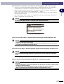
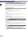
YAMAHA SINGLE-AXIS ROBOT
YMS
FLIP-X series
User’s Manual
ENGLISH
E
YAMAHA MOTOR CO., LTD.
IM Operations
882 Soude, Naka-ku, Hamamatsu, Shizuoka 435-0054.Japan
URL http://www.yamaha-motor.jp/robot/index.html
E36-Ver. 1.04
Introduction
The YAMAHA YMS series is a family of single-axis industrial robots that use the absolute positioning method as a standard feature to improve ease of use, resistance to environmental conditions
and maintenance work. A wide varaiety of product lineup allows you to select the desired robot
model that best matches your application.
This instruction manual describes the safety measures, handling, adjustment and maintenance of
YMS series robots for correct, safe and effective use. Be sure to read this manual carefully before
installing the robot. Even after you have read this manual, keep it in a safe and convenient place
for future reference.
This instruction manual should be used with the robot and considered an integral part of it. When
the robot is moved, transferred or sold, send this manual to the new user along with the robot. Be
sure to explain to the new user the need to read through this manual.
Specifications of robot models other than standard models may be omitted in this manual if they
are common to those of standard models. In this case, refer to the specifications of standard models.
For details on specific operation and programming of the robot, refer to the separate "YAMAHA
Robot Controller User's Manual".
NOTES
• The contents of this manual are subject to change without prior notice.
• Information furnished by YAMAHA in this manual is believed to be reliable. However, if you
find any part unclear or inaccurate in this manual, please contact YAMAHA sales office or
dealer.
YAMAHA MOTOR CO., LTD.
IM Operations
i
MEMO
ii
General Contents
Chapter 1
Safety
1-1
1-2
1-3
1-4
1-5
1-6
1-7
1-8
1-9
1-10
1-11
Chapter 2
Product Features And Operating Cautions
2-1
2-2
2-3
Chapter 3
Safety Information ............................................................................................ 1-1
Essential Caution Items ..................................................................................... 1-2
Special Training for Industrial Robot Operation ............................................... 1-6
Robot Safety Functions ..................................................................................... 1-6
Safety Measures for the System ........................................................................ 1-7
Trial Operation ................................................................................................. 1-7
Work Within the Safeguard Enclosure .............................................................. 1-8
Automatic Operation ........................................................................................ 1-8
Adjustment and Inspection ............................................................................... 1-9
Repair and Modification ................................................................................... 1-9
Warranty .......................................................................................................... 1-9
Product Features ............................................................................................... 2-1
Robot part names (Fig. 1) ................................................................................. 2-2
Operating Cautions .......................................................................................... 2-3
Installation and Connections
3-1
3-2
Installation Cautions ......................................................................................... 3-1
Installing the robot ........................................................................................... 3-2
3-2-1
3-2-2
3-3
3-4
Attaching the end effector ................................................................................ 3-5
Connections ...................................................................................................... 3-6
3-5
3-6
Setting the parameters ...................................................................................... 3-6
Trial Operation ................................................................................................. 3-6
3-4-1
Chapter 4
Connecting the robot cables ................................................................................ 3-6
Periodic inspection and maintenance
4-1
Chapter 5
Installation Using The Body Mounting Taps ......................................................... 3-2
Installation Using The T-Slots .............................................................................. 3-3
Before beginning work ..................................................................................... 4-1
Specifications
5-1
Robot specifications ......................................................................................... 5-1
5-1-1
5-1-2
YMS45 ................................................................................................................. 5-1
YMS55 ................................................................................................................. 5-2
i
MEMO
ii
Chapter 1
1-1
Safety
Safety Information
Warning information in this manual is shown classified into the following items.
w
w
c
n
DANGER
FAILURE TO FOLLOW DANGER INSTRUCTIONS WILL RESULT IN SEVERE INJURY OR DEATH TO THE
ROBOT OPERATOR, BYSTANDERS OR PERSONS INSPECTING OR REPAIRING THE ROBOT.
WARNING
FAILURE TO FOLLOW WARNING INSTRUCTIONS COULD RESULT IN SEVERE INJURY OR DEATH TO THE
ROBOT OPERATOR, BYSTANDERS OR PERSONS INSPECTING OR REPAIRING THE ROBOT.
CAUTION
Failure to follow CAUTION instructions may result in injury to the robot operator, bystanders or persons
inspecting or repairing the robot, or damage to the robot and/or robot controller.
NOTE
Explains the key point in the operation in a simple and clear manner.
It is not possible to list all safety items in detail within the limited space of this manual. So it is
essential that the user have a full knowledge of basic safety rules and also that the operator makes
correct judgments on safety procedures during operation.
This manual and warning labels supplied with or affixed to the robot are written in English. If the
robot operator or service personnel does not understand English, do not permit that person to
handle the robot.
1-
1
1
Safety
Industrial robots are highly programmable, mechanical devices that provide a large degree of
freedom when performing various manipulative tasks.
To ensure correct and safe use of YAMAHA industrial robots, carefully read this manual and make
yourself well acquainted with the contents. FOLLOW THE WARNINGS, CAUTIONS AND
INSTRUCTIONS INCLUDED IN THIS MANUAL. Failure to take necessary safety measures or
mishandling due to not following the instructions in this manual may result in trouble or damage to
the robot and injury to personnel (robot operator or service personnel) including fatal accidents.
1-2 Essential Caution Items
1-2
Essential Caution Items
Particularly important cautions for handling or operating the robot are described below. In addition, safety information about installation, operation, inspection and maintenance is provided in
each chapter. Be sure to comply with these instructions to ensure safe use of the robot.
Safety
1
(1) Observe the following cautions during automatic operation.
• Install a safeguard (protective enclosure) to keep any person from entering within the movement
range of the robot and suffering injury due to being struck by moving parts.
• Install a safety interlock that triggers emergency stop when the door or panel is opened.
• Install safeguards so that no one can enter inside except from doors or panels equipped with
safety interlocks.
• The warning labels shown in Fig. 1-1 are supplied with the robot and should be affixed to conspicuous spots on doors or panels equipped with safety interlocks.
w
DANGER
SERIOUS INJURY OR DEATH WILL RESULT FROM IMPACT WITH MOVING ROBOT.
• KEEP OUTSIDE OF GUARD DURING OPERATION.
• LOCK OUT POWER BEFORE APPROACHING ROBOT.
(2) Use caution to prevent hands or fingers from being pinched or crushed.
Warning labels 2 (Fig. 1-2) are affixed to the robot.
When moving the robot or performing teaching, use caution to prevent hand or fingers from being
pinched or crushed by the robot movable parts.
w
WARNING
MOVING PARTS CAN PINCH OR CRUSH.
KEEP HANDS AWAY FROM ROBOT ARMS.
DANGER
Serious injury or death
will result from impact
with moving robot.
• Keep outside of guard
during operation.
• Lock out power before
approaching robot.
Fig. 1-1 Warning label 1
2
1-
WARNING
Moving parts can
pinch or crush.
Keep hands away
from robot arms.
Fig. 1-2 Warning label 2
1-2 Essential Caution Items
(3) Follow the instructions on listed on warning labels and in this manual.
• Be sure to read the warning labels and this manual carefully and make sure you thoroughly
understand their contents before attempting installation and operation of the robot.
• Before starting robot operation, be sure to reread the procedures and cautions relating to your
work as well as descriptions in this chapter (Chapter 1, "Safety").
• Never install, adjust, inspect or service the robot in any manner that does not comply with the
instructions in this manual.
• The warning labels shown in Fig. 1-3 are supplied with the robot and should be affixed to the
robot or conspicuous spots near the robot.
Safety
w
1
WARNING
IMPROPER INSTALLATION OR OPERATION CAN RESULT IN SERIOUS INJURY OR DEATH.
READ THE USER'S MANUAL AND ALL WARNING LABELS BEFORE OPERATION.
WARNING
Improper Installation or operation
can result in serious injury or
death.
Read user's(owner's)
manual and all warning labels
before operation.
Fig. 1-3 Warning label 3
(4) Do not use the robot in environments containing inflammable gas, etc.
w
WARNING
• THIS ROBOT WAS NOT DESIGNED FOR OPERATION IN ENVIRONMENTS WHERE INFLAMMABLE OR
EXPLOSIVE SUBSTANCES ARE PRESENT.
• DO NOT USE THE ROBOT IN ENVIRONMENTS CONTAINING INFLAMMABLE GAS, DUST OR LIQUIDS.
EXPLOSIONS OR FIRE MIGHT OTHERWISE RESULT.
(5) Do not use the robot in locations possibly subject to electromagnetic interference, etc.
w
WARNING
AVOID USING THE ROBOT IN LOCATIONS SUBJECT TO ELECTROMAGNETIC INTERFERENCE, ELECTROSTATIC DISCHARGE OR RADIO FREQUENCY INTERFERENCE. MALFUNCTIONS MIGHT OTHERWISE
OCCUR.
(6) Use caution when releasing the brake of a vertical use robot.
w
WARNING
THE VERTICAL AXIS WILL SLIDE DOWN WHEN THE BRAKE IS RELEASED, CAUSING A HAZARDOUS
SITUATION.
• PRESS THE EMERGENCY STOP BUTTON AND PROP UP THE VERTICAL AXIS WITH A SUPPORT STAND
BEFORE RELEASING THE BRAKE.
• BE CAREFUL NOT TO LET YOUR BODY GET CAUGHT BETWEEN THE VERTICAL AXIS AND
INSTALLATION BASE WHEN RELEASING THE BRAKE TO PERFORM DIRECT TEACH.
3
1-
1-2 Essential Caution Items
(7) Provide safety measures for end effector (gripper, etc.).
w
Safety
1
WARNING
• END EFFECTORS MUST BE DESIGNED AND MANUFACTURED SO THAT THEY CREATE NO HAZARDS
(FOR EXAMPLE, A WORKPIECE THAT COMES LOOSE) EVEN IF POWER (ELECTRICITY, AIR PRESSURE,
ETC.) IS SHUT OFF OR POWER FLUCTUATIONS OCCUR.
• IF THERE IS A POSSIBLE DANGER THAT THE OBJECT GRIPPED BY THE END EFFECTOR MAY FLY OFF
OR DROP, THEN PROVIDE APPROPRIATE SAFETY PROTECTION TAKING INTO ACCOUNT THE OBJECT
SIZE, WEIGHT, TEMPERATURE AND CHEMICAL PROPERTIES.
(8) Cautions when removing the motor and brake. (Vertical use robots)
w
WARNING
THERE IS A HIGH RISK THAT THE UP/DOWN AXIS WILL FALL WHEN REMOVING THE MOTOR AND
BRAKE.
• TURN OFF THE ROBOT CONTROLLER AND PROP UP THE VERTICAL AXIS WITH A SUPPORT STAND
BEFORE REMOVING THE MOTOR.
• BE CAREFUL NOT TO LET YOUR BODY GET CAUGHT BETWEEN THE VERTICAL AXIS PARTS AND
INSTALLATION BASE.
(9) Take the following safety precautions during inspection of controller.
w
WARNING
• WHEN YOU NEED TO TOUCH THE TERMINALS OR CONNECTORS ON THE OUTSIDE OF THE
CONTROLLER DURING INSPECTION, ALWAYS FIRST TURN OFF THE CONTROLLER POWER SWITCH
AND ALSO THE POWER SOURCE IN ORDER TO PREVENT POSSIBLE ELECTRICAL SHOCK.
• NEVER TOUCH ANY INTERNAL PARTS OF THE CONTROLLER.
• REFER TO THE "YAMAHA ROBOT CONTROLLER USER'S MANUAL" FOR PRECAUTIONS ON
HANDLING THE CONTROLLER.
(10) Consult us for corrective action when the robot is damaged or malfunctions occur.
w
WARNING
IF ANY PART OF THE ROBOT IS DAMAGED OR ANY MALFUNCTION OCCURS, CONTINUING THE OPERATION MAY BE VERY DANGEROUS. PLEASE CONSULT YOUR YAMAHA SALES OFFICE OR DEALER FOR
CORRECTIVE ACTION.
Damage or Trouble
Possible Danger
Damage to machine harness or robot cable
Electrical shock, malfunction of robot
Damage to exterior of robot
Flying outwards of damaged parts during robot
operation
Abnormal operation of robot
(positioning error, excessive vibration, etc.)
Malfunction of robot
Z-axis brake trouble
Dropping of load
(11) Be careful not to touch the motor or speed reduction gear casing when hot.
w
1-
4
WARNING
THE MOTOR AND SPEED REDUCTION GEAR CASING ARE EXTREMELY HOT AFTER AUTOMATIC OPERATION, SO BURNS MAY OCCUR IF THESE ARE TOUCHED.
BEFORE HANDLING THESE PARTS DURING INSPECTION OR SERVICING, TURN OFF THE CONTROLLER,
WAIT FOR A WHILE AND CHECK THAT THE PART HAS COOLED.
1-2 Essential Caution Items
(12) Do not remove, alter or stain the warning labels.
w
(13) Protective bonding
w
WARNING
BE SURE TO GROUND THE ROBOT AND CONTROLLER TO PREVENT ELECTRICAL SHOCK.
(14) Be sure to make correct parameter settings.
c
CAUTION
The robot must be operated with correct acceleration coefficients according to the tolerable moment of
inertia and manipulator tip mass or moment of inertia. If these are not correct, drive unit service life may
end prematurely, and damage to robot parts or residual vibration during positioning may result.
1-
5
1
Safety
WARNING
IF WARNING LABELS ARE REMOVED OR DIFFICULT TO SEE, THEN ESSENTIAL PRECAUTIONS MIGHT
NOT BE TAKEN, RESULTING IN ACCIDENTS.
• DO NOT REMOVE, ALTER OR STAIN THE WARNING LABELS ON THE ROBOT.
• DO NOT ALLOW THE WARNING LABELS TO BE HIDDEN BY DEVICES INSTALLED ONTO THE ROBOT BY
THE USER.
• PROVIDE PROPER LIGHTING SO THAT THE SYMBOLS AND INSTRUCTIONS ON THE WARNING LABELS
CAN BE CLEARLY SEEN EVEN FROM OUTSIDE THE SAFEGUARD ENCLOSURE.
1-3 Special Training for Industrial Robot Operation
1-3
Special Training for Industrial Robot Operation
Companies or factories using industrial robots must make sure that every person, who handles the
robot such as for teaching, programming, movement check, inspection, adjustment and repair, has
received appropriate training and also has the skills needed to perform the job correctly and safely.
Since the YMS series robots fall under the industrial robot category, the user must observe local
regulations and safety standards for industrial robots, and provide special training for every person
involved in robot-related tasks (teaching, programming, movement check, inspection, adjustment,
repair, etc.).
Safety
1
1-4
Robot Safety Functions
(1) Overload detection
This function detects an overload applied to the motor and shuts off the servo power.
If an overload condition occurs, take the following measures.
1. Insert a timer in the program.
2. Reduce the acceleration coefficient.
(2) Soft limits
Soft limits can be set on each axis to limit the working envelope in manual operation after returnto-origin and during automatic operation.
Note: The working envelope is the area limited by soft limits.
(3) Mechanical stoppers
If the servo power is suddenly shut off during high-speed operation by emergency stop or safety
functions, these mechanical stoppers prevent the axis from exceeding the movement range.
Note: The movement range is the area limited by mechanical stoppers.
w
WARNING
AXIS MOVEMENT WILL NOT STOP IMMEDIATELY AFTER THE SERVO POWER SUPPLY IS SHUT OFF BY
EMERGENCY STOP OR OTHER SAFETY FUNCTIONS.
(4) Vertical axis brake
An electromagnetic brake is installed on the vertical use robot to prevent the vertical axis from
sliding down when servo power is turned off. This brake is working when the controller is off or
the vertical axis servo power is off even when the controller is on.
The vertical axis brake can be released by means of the programming unit or by a command in the
program when the controller is on.
w
6
1-
WARNING
THE VERTICAL AXIS WILL SLIDE DOWN WHEN THE BRAKE IS RELEASED, CREATING A HAZARDOUS
SITUATION.
• PRESS THE EMERGENCY STOP BUTTON AND PROP THE VERTICAL AXIS WITH A SUPPORT STAND
BEFORE RELEASING THE BRAKE.
• USE CAUTION NOT TO LET YOUR BODY GET CAUGHT BETWEEN THE VERTICAL AXIS AND
INSTALLATION BASE WHEN RELEASING THE BRAKE TO PERFORM DIRECT TEACH.
1-5 Safety Measures for the System
1-5
Safety Measures for the System
1-6
Trial Operation
After making installations, adjustments, inspections, or maintenance or repairs to the robot, make a
trial run using the following procedures.
(1) If a safeguard enclosure has not yet been provided right after installation
of the robot, rope off or chain off around the movement area of the manipulator in place of the safeguard, and observe the following points.
1. Use sturdy, stable posts which will not fall over easily.
2. The rope or chain should be easily visible by everyone around the robot.
3. Place a sign to keep the operator or other personnel from entering the movement range of the
manipulator.
(2) Check the following points before turning on the controller.
1.
2.
3.
4.
5.
6.
Is the robot securely and correctly installed?
Are the electrical connections to the robot correct?
Are items such as air pressure correctly supplied?
Is the robot correctly connected to peripheral equipment?
Have safety measures (safeguard enclosure, etc.) been taken?
Does the installation environment meet the specified standards.
(3) After the controller is turned on, check the following points from outside
the safeguard enclosure.
1.
2.
3.
4.
5.
6.
7.
8.
Does the robot start and stop as intended? Can the operation mode be selected correctly?
Does each axis move as intended within the soft limits?
Does the end effector move as intended?
Are the signal transmissions to the end effector and peripheral equipment correct?
Does emergency stop work?
Are the teaching and playback functions normal?
Are the safeguard enclosure and interlock working as intended?
Does the robot move correctly during automatic operation?
1-
7
1
Safety
Since the robot is commonly used in conjunction with an automated system, dangerous situations
are more likely to occur from the automated system than from the robot itself. Accordingly, appropriate safety measures must be taken on the part of the system manufacturer according to the
individual system. The system manufacturer should provide a proper instruction manual for safe,
correct operation and servicing of the system.
1-7 Work Within the Safeguard Enclosure
1-7
Work Within the Safeguard Enclosure
(1) Work within the safeguard enclosure
1
Safety
When work is required inside the safeguard enclosure, always turn off the controller and place a
sign indicating that the robot is being adjusted or serviced in order to keep any other person from
touching the controller switch or operation panel, except for the following cases.
1) Soft limit settings (See Section 4 in Chapter 4.)
2) Teaching
For item 1), follow the precautions and procedure for each section. To perform item 2), refer to the
description in (2) below.
(2) Teaching
When performing teaching within the safeguard enclosure, comply with the instructions listed
below.
1) Check or perform the following points from outside the safeguard enclosure.
1. Make sure that no hazards are present within the safeguard enclosure by a visual check.
2. Check that the programming unit HPB or TPB operates correctly.
3. Check that no failures are found in the robot.
4. Check that emergency stop works correctly.
5. Select teaching mode and prohibit automatic operation.
2) Never enter the movement range of the manipulator while within the safeguard enclosure.
1-8
Automatic Operation
Automatic operation described here includes all operations in AUTO mode.
(1) Check the following before starting automatic operation.
1.
2.
3.
4.
No one is within the safeguard enclosure.
The programming unit and tools are in their specified locations.
The alarm or error lamps on the robot and peripheral equipment do not flash.
The safeguard enclosure is securely installed with safety interlocks actuated.
(2) Observe the following during automatic operation or in cases where an error occurs.
1) After automatic operation has started, check the operation status and warning lamp to ensure that
the robot is in automatic operation.
2) Never enter the safeguard enclosure during automatic operation.
3) If an error occurs in the robot or peripheral equipment, observe the following procedure before
entering the safeguard enclosure.
1. Press the emergency stop button to set the robot to emergency stop.
2. Place a sign on the start switch, indicating that the robot is being inspected in order to keep
any other person from touching the start switch and restarting the robot.
8
1-
1-9 Adjustment and Inspection
1-9
Adjustment and Inspection
Do not attempt any installation, adjustment, inspection or maintenance unless it is described in this
manual.
Safety
1-10 Repair and Modification
1
Do not attempt any repair, parts replacement and modification unless described in this manual.
These works require technical knowledge and skill, and may also involve work hazards.
1-11 Warranty
For information on the warranty period and terms, please contact our distributor where you purchased the product.
This warranty does not cover any failure caused by:
1.Installation, wiring, connection to other control devices, operating methods, inspection or maintenance that does not comply with industry standards or instructions specified in the YAMAHA
manual;
2.Usage that exceeded the specifications or standard performance shown in the YAMAHA manual;
3.Product usage other than intended by YAMAHA;
4.Storage, operating conditions and utilities that are outside the range specified in the manual;
5.Damage due to improper shipping or shipping methods;
6.Accident or collision damage;
7.Installation of other than genuine YAMAHA parts and/or accessories;
8.Modification to original parts or modifications not conforming to standard specifications designated by YAMAHA, including customizing performed by YAMAHA in compliance with distributor or customer requests;
9.Pollution, salt damage, condensation;
10. Fires or natural disasters such as earthquakes, tsunamis, lightning strikes, wind and flood damage,
etc;
11. Breakdown due to causes other than the above that are not the fault or responsibility of
YAMAHA;
The following cases are not covered under the warranty:
1.Products whose serial number or production date (month & year) cannot be verified.
2.Changes in software or internal data such as programs or points that were created or changed by
the customer.
3.Products whose trouble cannot be reproduced or identified by YAMAHA.
4.Products utilized, for example, in radiological equipment, biological test equipment applications
or for other purposes whose warranty repairs are judged as hazardous by YAMAHA.
THE WARRANTY STATED HEREIN PROVIDED BY YAMAHA ONLY COVERS DEFECTS IN
PRODUCTS AND PARTS SOLD BY YAMAHA TO DISTRIBUTORS UNDER THIS AGREEMENT. ANY AND ALL OTHER WARRANTIES OR LIABILITIES, EXPRESS OR IMPLIED,
INCLUDING BUT NOT LIMITED TO ANY IMPLIED WARRANTIES OF MERCHANTABILITY
OR FITNESS FOR A PARTICULAR PURPOSE ARE HEREBY EXPRESSLY DISCLAIMED BY
YAMAHA. MOREOVER, YAMAHA SHALL NOT BE HELD RESPONSIBLE FOR CONSEQUENT OR INDIRECT DAMAGES IN ANY MANNER RELATING TO THE PRODUCT.
Ver.1.00_201205
9
1-
MEMO
10
1-
Chapter 2
Product Features And Operating Cautions
2-1
Product Features
This is a single-axis robot with a linear motion rod that permits positioning to any desired position.
1. Compact Design
2
The built-in YMS series motor features a no-coupling, compact design, resulting in an overall
length that is the shortest in its class.
Although the built-in motor is connected directly to the ballscrew, the motor can be removed
independently. This permits quick and easy maintenance, with minimal downtime in the event of a
problem.
3. Durable
Long-term maintenance-free operation is achieved due to a lubrication unit that uses a high oil
content fiber net for the ballscrew nut section, and a contact scraper for the rod bearing section.
Long-term maintenance-free operation is especially important on rod type robots due to the difficulty in disassembling them. Moreover, the contact scraper also serves to prevent instability (looseness) when the rod is extended.
4. High Reliability
The position detection mechanism features a resolver that ensures highly reliable operation in a
wide variety of environments.
5. Low Cost
High level functions at a low cost. Paired with the multi-function ERCD controller which now
offers a new pulse train input function, this robot reduces both the time and cost of constructing a
system.
6. Absolute function
This robot can also be paired with the ERCX controller to enable an absolute position function
which requires no return-to-origin at power ON.
1
2-
Product Features And Operating Cautions
2. Superior Maintainability
2-2 Robot part names (Fig. 1)
2-2
Robot part names (Fig. 1)
Built-in AC servo motor
Lubrication port
2
Lubrication unit using high oil content fiber net
Product Features And Operating Cautions
Ball screw
T-slot
Contact scraper
Body mounting tap
Mechanical stopper position adjusting bolt *
Rod
* The mechanical stopper is factory-adjusted to the optimal position, and its adjusting bolt should
never be loosened. If accidentally loosened, please contact your YAMAHA representative for
assistance.
w
2
2-
WARNING
POSITIONAL DEVIATIONS WILL OCCUR IF THE MECHANICAL STOPPER ADJUSTING BOLT LOOSENED.
2-3 Operating Cautions
2-3
Operating Cautions
• Do not exceed the load weight capacity specified in the catalog.
• Specify the appropriate parameter settings with reference to Chapter 3, Section 3-5 (Setting the
parameters).
• This robot's return-to-origin direction is toward the motor only, and must not be changed.
2
Product Features And Operating Cautions
Motor
Return-to-origin direction
• Be sure that the robot's return-to-origin motion range is free of external interference/obstacles.
w
WARNING
MALFUNCTIONS WILL OCCUR IF THE RETURN-TO-ORIGIN DIRECTION IS SET IN THE DIRECTION OPPOSITE FROM THE MOTOR. MOREOVER, THE PRESENCE OF OBSTACLES/INTERFERENCE IN THE RETURNTO-ORIGIN RANGE WILL RESULT IN POSITIONAL DEVIATIONS.
2-
3
MEMO
4
2-
Chapter 3
Installation and Connections
3-1
Installation Cautions
* Install in a manner which ensures that radial loads are not applied to the rod.
3
Installation and Connections
* The rotation direction's inertial moment must not applied to the rod.
* When the robot body is mounted in a horizontal posture, the load must be supported by the linear
guide and the bushing.
(Fig. 1)
Linear guide
Ball bushing
CAUTION
Applying radial loads and the inertial moment to the rod win‚ shorten the robot life, and cause robot
failures.
3-
1
3-2 Installing the robot
3-2
Installing the robot
3-2-1
Installation Using The Body Mounting Taps
Install the robot using the 4 body mounting taps located at the end of the robot body, as shown
below.
(Fig. 2)
Installation and Connections
3
* Mount the robot body using all 4 of the taps. Failure to secure all 4 of the screws may result in
insufficient rigidity.
YMS45
Mounting bolt type: M4 × 0.7
Mounting bolt nominal length:
The mounting tap depth is 10mm. The selected screws should therefore have an engaged nominal
length of between 6mm and 10mm.
YMS55
Mounting bolt type: M5 × 0.8
Mounting bolt nominal length:
The mounting tap depth is 12mm. The selected screws should therefore have an engaged nominal
length of between 8mm and 12mm.
2
3-
3-2 Installing the robot
3-2-2
Installation Using The T-Slots
The robot body can also be mounted by using the T-slots located on the side of the robot body (see
Fig. 3). Place nuts in the T-slots, then use bolts to secure the body.
(Fig. 3)
3
* Mounting nuts
w
Installation and Connections
* Mounting bolts
YMS45: M3
YMS55: M4
Use commercially available square nuts (material: steel or SUS).
WARNING
BE SURE TO USE STEEL OR SUS SQUARE NUTS. USING SQUARE NUTS OF OTHER MATERIALS CAN
CAUSE THREAD FAILURE AND BEARING SURFACE PITTING, ETC., RESULTING IN INSUFFICIENT
MOUNTING TIGHTNESS.
3-
3
3-2 Installing the robot
* Mounting bolt quantity:
4 bolts or more
Use Both the T-slots on each face, with 2 or more bolts in each T-slot.
* Bolt positions
The outermost bolts should be located near the ends of the T-slots, and the bolt pitch should be
uniform.
(Fig. 4) Layout
: Good example/Bad example
Installation and Connections
3
Pitch
w
: Good example/Bad example
WARNING
BE SURE TO USE BOTH THE T-SLOTS, WITH 2 OR MORE BOLTS BEING SECURED IN EACH T-SLOT
(TOTAL OF 4 OR MORE BOLTS).
* Mounting bolt nominal length:
After verifying the T-slot dimensions at the outline drawing (Chapter 5, Specifications), select a
bolt nominal length which provides adequate engagement with the nut.
w
w
4
3-
WARNING
A BOLT WHICH HAS INSUFFICIENT ENGAGEMENT WITH THE NUT CAN CAUSE LOOSENESS AND
THREAD FAILURE, RESULTING IN INSUFFICIENT MOUNTING TIGHTNESS.
WARNING
IF THE ROBOT BODY IS MOUNTED IN A VERTICAL POSTURE USING THE T-SLOT MOUNTING FORMAT,
BOLT LOOSENING CAN CAUSE THE ROBOT BODY TO FALL, POSSIBLY RESULTING IN A SERIOUS
ACCIDENT. SAFETY MEASURES SHOULD THEREFORE BE TAKEN TO PREVENT BOLT LOOSENING AND
ROBOT FALLS.
3-3 Attaching the end effector
3-3
Attaching the end effector
To mount the end effector, insert its mounting hole onto the rod's threaded end, then secure it with
a nut, as shown below.
(Fig. 5)
3
Installation and Connections
* If the robot is mounted in a vertical posture, configure so that the end effector and workpiece
center of gravity is aligned with that of the rod. In cases where this is not possible, support the
offset load with the bushing and linear guide, etc., so that the inertial moment is not applied
directly to the rod.
* If the robot is mounted in a horizontal posture, support the load with the bushing and linear
guide, etc., so that the inertial moment is not applied directly to the rod.
* Take appropriate measures to prevent nut loosening.
w
WARNING
FAILURE TO TAKE MEASURES TO PREVENT LOOSENING CAN CAUSE THE END EFFECTOR TO FALL
OFF DURING OPERATION, POSSIBLY RESULTING IN A SERIOUS ACCIDENT.
3-
5
3-4 Connections
3-4
Connections
3-4-1
Connecting the robot cables
Plug the cable from robot body into the robot cable connector, then cover the connection with the
hood.
Installation and Connections
3
3-5
Setting the parameters
Specify a load capacity parameter setting (PRM3) which is equivalent to the sum of the end effector and workpiece weights. For setting procedure details, refer to the ERCD/ERCX controller
user's manual.
3-6
Trial Operation
Execute a return-to-origin operation.
Begin automatic operation in the low-speed mode.
If no problems are observed, execute high-speed automatic operation.
3-
6
Chapter 4
4-1
Periodic inspection and maintenance
Before beginning work
Periodic inspection and maintenance are essential to ensure safe and efficient operation of
YAMAHA robots. This chapter describes periodic inspection items and procedures for the YMS
series. Before beginning work, read the precautions below and also in Chapter 1 "Safety" and
follow the instructions.
w
WARNING
• WHEN THE ROBOT DOES NOT NEED TO BE OPERATED DURING ADJUSTMENT OR MAINTENANCE,
ALWAYS TURN OFF THE CONTROLLER AND THE EXTERNAL SWITCH BOARD.
• DO NOT TOUCH INTERNAL PARTS OF THE CONTROLLER FOR 5 SECONDS AFTER THE CONTROLLER
HAS BEEN TURNED OFF.
• WHEN ONLY MAKING ELECTRICAL INSPECTIONS AND REQUIRING NO MECHANICAL MOVEMENT OF
THE ROBOT, KEEP THE EMERGENCY STOP BUTTON PRESSED.
• USE ONLY LUBRICANT AND GREASES SPECIFIED BY YAMAHA SALES OFFICE OR REPRESENTATIVE.
• USE ONLY PARTS SPECIFIED BY YAMAHA SALES OFFICE OR REPRESENTATIVE. TAKE SUFFICIENT
CARE NOT TO ALLOW ANY FOREIGN MATTER TO CONTAMINATE THEM DURING ADJUSTMENT, PARTS
REPLACEMENT OR REASSEMBLY.
• DO NOT MODIFY ANY PARTS ON THE ROBOT OR CONTROLLER. MODIFICATION MAY RESULT IN
UNSATISFACTORY SPECIFICATIONS OR THREATEN OPERATOR SAFETY.
• WHEN ADJUSTMENT OR MAINTENANCE IS COMPLETE, RETIGHTEN THE BOLTS AND SCREWS
SECURELY.
• DURING ROBOT ADJUSTMENT OR MAINTENANCE, PLACE A SIGN INDICATING THAT THE ROBOT IS
BEING ADJUSTED OR SERVICED TO PREVENT OTHERS FROM TOUCHING THE CONTROL KEYS OR
SWITCHES. PROVIDE A LOCK ON THE SWITCH KEYS OR ASK SOMEONE TO KEEP WATCH AS
NEEDED.
When applying grease to the internal linear guide, take the following precautions.
w
WARNING
PRECAUTIONS WHEN HANDLING GREASE:
• INFLAMMATION MAY OCCUR IF THIS GETS IN THE EYES.
BEFORE HANDLING THE GREASE, WEAR YOUR SAFETY GOGGLES TO ENSURE THE GREASE WILL
NOT COME IN CONTACT WITH THE EYES.
• INFLAMMATION MAY OCCUR IF THE GREASE COMES INTO CONTACT WITH SKIN. BE SURE TO WEAR
PROTECTIVE GLOVES TO PREVENT CONTACT WITH SKIN.
• DO NOT TAKE ORALLY OR EAT. (EATING WILL CAUSE DIARRHEA AND VOMITING.)
• HANDS AND FINGERS MIGHT BE CUT WHEN OPENING THE GREASE CONTAINER, SO USE
PROTECTIVE GLOVES.
• KEEP OUT OF THE REACH OF CHILDREN.
• DO NOT HEAT THE GREASE OR PLACE NEAR AN OPEN FLAME SINCE THIS COULD LEAD TO SPARKS
AND FIRES.
EMERGENCY TREATMENT:
• IF GREASE GETS IN THE EYES, WASH LIBERALLY WITH PURE WATER FOR ABOUT 15 MINUTES AND
CONSULT A PHYSICIAN FOR TREATMENT.
• IF GREASE COMES IN CONTACT WITH THE SKIN, WASH AWAY COMPLETELY WITH SOAP AND WATER.
• IF TAKEN INTERNALLY, DO NOT INDUCE VOMITING BUT PROMPTLY CONSULT A PHYSICIAN FOR
PROPER TREATMENT.
4-
1
4
Periodic inspection and maintenance
w
DANGER
IF THE INSPECTION OR MAINTENANCE PROCEDURE CALLS FOR OPERATION OF THE ROBOT, STAY
OUT OF THE WORKING AREA OF THE ROBOT DURING OPERATION. DO NOT TOUCH ANY PARTS INSIDE
THE CONTROLLER.
KEEP WATCHING THE ROBOT MOVEMENT AND SURROUNDING AREA SO THAT THE OPERATOR CAN
PRESS THE EMERGENCY STOP BUTTON IF ANY DANGER OCCURS.
4-1 Before beginning work
Daily inspection
Check the following points on a daily basis, before and after robot operation.
Checkpoints
Check items
Cables
Check for scratches, dents, excessive bends. Verify that the
connector is securely plugged in.
Robot
Check for unusual vibration and noise.
Six-month inspection
Applying grease
Lubricate by using a grease gun to apply grease at the lubrication port.
(1) Lower the shaft by manual operation to a point 50mm above the origin position.
Periodic inspection and maintenance
4
(2) Open the lubrication port cover.
(3) Use a grease gun to apply grease (several cc) to the ballscrew.
Grease gun
2
4-
Chapter 5
Specifications
5-1
Robot specifications
5-1-1
YMS45
Basic specifications
YMS45
Robot model
30
Motor output (W)
±0.02
Repetitive positioning accuracy (mm)
Ball screw (C10 Class)/φ8mm
Reduction mechanism
Ball screw lead (mm)
12
6
600
300
Horizontal use
4.5
6
Vertical use
1
2
Thrust rating (N)*1
32
64
Stroke (mm)
50 to 200 (50 pitch)
Cable length
3.5m (standard cable), 5m or 10m
Maximum speed (mm/sec)
Maximum payload (kg)
5
Specifications
ERCD/ERCX (3A)*2
Compatible controllers
*1 : The thrust control accuracy is not guaranteed.
*2 : This is the required power supply capacity. An insufficient power supply capacity can reduce performance.
*Be sure that radial loads are not applied to the rod.
YMS45 (BK spec.)
1.5
10 9
22
8.5 (Width across flats)
(5)
(42.5)
2
φ41
Ballscrew
lubrication hole
54.5
φ20
20
M10 x 1.25
Effective stroke
(5)
4-M4 x 0.7 Depth10
(90° evenly spaced)
45
25
14
45°
A
P.C
.D
.53
t1 cover
1.9
38 (with brake) (Screw height) (Not used when brake is installed)
Approx. 250 (Motor cable length)
B
L1
14
25
45
L
45
Mounting nut dimension
Effective stroke
L1
L
Weight (kg)*1
50
136.5
212.5
1.1
100
186.5
262.5
1.3
150
236.5
312.5
1.5
200
286.5
362.5
1.7
52
5.8
22.5
1.5
3.5
M10 x 1.25
17
(19.6)
6
3.3
Detail of section B
VIEW A
*1: Weight without brake. When a brake is installed, the weight is 0.2kg heavier than
the table values for the brakeless body weight.
1
5-
5-1 Robot specifications
5-1-2
YMS55
Basic specifications
YMS55
Robot model
30
Motor output (W)
±0.02
Repetitive positioning accuracy (mm)
Ball screw (C10 Class)/φ12mm
Reduction mechanism
Ball screw lead (mm)
12
6
Maximum speed (mm/sec)*1
600
300
Horizontal use
5
9
Vertical use
1.5
4
32
64
Maximum payload (kg)
Thrust rating
Stroke (mm)
50 to 300 (50 pitch)
Cable length
3.5m (standard cable), 5m or 10m
ERCD/ERCX (4.5A)*3
Compatible controllers
*1 : When the stroke is 300mm, the maximum speeds are 450mm/sec and 225mm/sec (75%).
*2 : The thrust control accuracy is not guaranteed.
*3 : This is the required power supply capacity. An insufficient power supply capacity can reduce performance.
*Be sure that radial loads are not applied to the rod.
YMS55 (BK spec.)
Ballscrew
lubrication hole
54.5
(5)
(45.5)
2
φ50
50
24
9.5 (Width across flats)
M12 x 1.25
φ25
25
1.5
10 10
(5)
Effective stroke
4-M5 x 0.8 Depth12
(90° evenly spaced)
55
30
17
45°
A
P.C
.D
t1 cover
1.9
(Screw height) (Not used when brake is
38 (with brake)
installed)
B
L1
Approx. 250 (Motor cable length)
1.5
Mounting nut dimension
Effective stroke
L1
L
Weight (kg)*1
5-
2
50
150.5
228.5
1.7
100
200.5
278.5
2
150
250.5
328.5
2.4
200
300.5
378.5
2.7
250
350.5
428.5
3.1
7.3
4.3
Detail of section B
300
400.5
478.5
3.4
56
M12 x 1.25
6.5
19
4.5
7
17
30
55
L
22 (21.9)
Specifications
5
(N)*2
55
VIEW A
*1: Weight without brake. When a brake is installed, the weight is 0.2kg heavier than
the table values for the brakeless body weight.
.65
MEMO
Revision record
Manual version Issue date
Description
Ver. 1.03
Jan. 2011
The description regarding "Warranty" was changed. The
external view in "5-1 Robot specifications" was modified.
Ver. 1.04
Jul. 2012
The description regarding "Warranty" was changed.
User's Manual
FLIP-X series
Single-axis Robot
YMS
Jul. 2012
Ver. 1.04
This manual is based on Ver. 1.05 of Japanese manual.
YAMAHA MOTOR CO., LTD. IM Operations
All rights reserved. No part of this publication may be reproduced in
any form without the permission of YAMAHA MOTOR CO., LTD.
Information furnished by YAMAHA in this manual is believed to be
reliable. However, no responsibility is assumed for possible
inaccuracies or omissions. If you find any part unclear in this manual,
please contact your distributor.