1
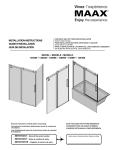
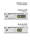
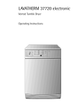
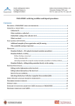
INSTRUCTION MANUAL
FOR
BENCH TOP CENTRIFUGE
Z 300
Z 400
Labnet International
PO Box 841
Woodbridge, NJ 07095
Phone: 732-417-0700
Fax: 732-417-1750
Z 300 / Z 400 / Jan. 2002
INDEX .................................................................................................................................... Page
1.
2.
3.
4.
5.
6.
7.
8.
9.
General Information
1.1 Precautions and hazards ..............................................................................
1.2 Description ....................................................................................................
1.3 Safety standards ...........................................................................................
1.4 Technical data Z 300 ....................................................................................
Technical data Z 400 ....................................................................................
1.5 Accessories supplied with each centrifuge unit ............................................
1.6 Warranty ........................................................................................................
Installation
2.1 Unpacking the centrifuge ..............................................................................
2.2 Transport .......................................................................................................
2.2 Required space .............................................................................................
2.3 Installation .....................................................................................................
How to install and load a rotor
3.1 Mounting and securing a swing out rotor ......................................................
3.2 Mounting and securing an angle rotor ..........................................................
3.3 Mounting and securing a hematocrit rotor ....................................................
3.4 Overloading of rotors.....................................................................................
3.5 Removing of the rotor....................................................................................
Operation
4.1 Power switch .................................................................................................
4.2 Lid release .....................................................................................................
4.3 Lid lock ..........................................................................................................
4.4 Preselection of speed ...................................................................................
4.5 Preselection of operating time ......................................................................
4.6 Keyboard - Starting the centrifuge - "quick"-key ...........................................
4.7 Key "stop" ......................................................................................................
Temperature
5.1 Temperature ..................................................................................................
Safety facilities
6.1 Imbalance ......................................................................................................
Service and Maintenance
7.1 Service and inspection of the centrifuge .......................................................
7.2 Cleaning the centrifuge .................................................................................
7.3 Cleaning the centrifuge after breakage of glass tubes/bottles .....................
7.4 Disinfection ....................................................................................................
Breakdown
8.1 Emergency lid release...................................................................................
8.2 Check list / Trouble shooting .........................................................................
Appendix
9.1 Chart for determining g-values ......................................................................
4E
5E
5E
6E
7E
8E
8E
8E
8E
8E
9E
9E
10 E
10 E
11 E
11 E
12 E
12 E
12 E
13 E
14 E
14 E
14 E
15 E
15 E
16 E
16 E
17 E
17 E
17 E
18 E
22 E
1.
General Information
1.1
Precautions and hazards
Before putting the centrifuge into operation, please read this instruction
manual carefully.
The centrifuge must not be operated by unqualified persons not familar with the
correct use and intended purpose of the machine. Please use only the original
spare parts.
For personal and enviromental safety, special attention has to be paid to the
following precautions:
The Hermle Centrifuges are neither explosion proof nor intert gas shielded and
should therefore never be operated in explosion-hazardais locations.
Never stay in the safety zone of 30 cm around the centrifuge or deposite
dangerous goods inside this zone during centrifugation.
The centrifugation of the flammable or explosive or radioactive samples is not
allowed.
Further more do not spin samples reacting chemically with each other with high
energy when explosed to air.
Never spin toxical or phatological material without adequate safety precautions i.e.
centrifuging of buckets/tubes without or with defective hermetic sealing is not
allowed.
The enduser is engaged to performe appropriate disinfection procedures in case
dangerous goods have contaminated the centrifuge or its accessories.
The general universal laboratory precautions should be observed in case infection
materials are centrifuged. If necessary, please contact your local security officer!
It is prohibited to run the centrifuge with rotors not suited for this centrifuge model.
Under no circumstances, the lid at the centrifuge should be opened while the rotor
is still turning respectively running with a speed of more than 2 meter per second.
The following rules must be strictly adhered to:
Do not operate the centrifuge in case it is not installed correctly.
Never operate the centrifuge in a dismounted state ( e.g. without covering sheet
metal)
Do not run the centrifuge when electrical or mechanical assembly groups have
been tampered with by unauthorized persons.
Never use accessories such as rotors and buckets which are not exclusively
approved by Hermle Labortechnik GmbH
GmbH, except commercially available
centrifuge tubes of glas or plastic.
Do not spin corrosive samples which may cause damages in material and impair
the mechanic resistance.
never operate the centrifuge with rotors or buckets which show any signs of
corrosion or mechanical damage
The manufacturer is only responsible for the security and reliability of the
centrifuge if:
The unit is operated according to the instruction manual.
Modifications, repairs and new adjustments are performed by HERMLE authorized
persons and the electrical installation of the location where the centrifuge is
operated corresponds to the IEC-regulations.
1.1
Description
The model Z 300 and Z 400 are a universal centrifuge which covers many fields of
applications by offering a wide range of accessories.
The centrifuges are equipped with the Hermle Standart-Control panel.
Speed and running time are set with easy to use control knobs.
The precise parameters selected are shown on the large digital LED display.
1.3
Safety standards
The centrifuge corresponds to the general requirements set by German law for
medical apparatus, "MedGV" group 3.
The following standards have been considered for the production of our
centrifuges:
- Accident prevention rules for centrifuges, UVV-VBG 7z.
- Accident prevention rules for electrical equipment & installations, UVV-VBG 4.
- International Standart IEC 1010-1 and IEC 1001-2-D
- European Standart PR EN 61010-1 and PR EN 61010-2-2
- Electrical interference suppression according to interference degree B as
per VDE 0871.
1.4
Technical data
______________________________________________________________________
Manufacturer
Hermle Labortechnik GmbH
______________________________________________________________________
Type
Z 300
______________________________________________________________________
Dimensions:
Width
35,5 cm
Depth
33 cm
Height
47,4 cm
______________________________________________________________________
Weight
27 kg
______________________________________________________________________
Noise level
65 dB(A)
______________________________________________________________________
Max. speed
Max. Volume
Max. RCF
Admiss. density
13.500 rpm
400 ml
17310 x g
1,2 kg/dm3
Admiss. kinetic energy
3 052 Nm
______________________________________________________________________
Electrical connection
Current
Connected load
230 V/50 Hz 1Ph
3,8 A
580 Watt
120 V/60 Hz 1Ph
4,0 A
460 Watt
______________________________________________________________________
Interference suppression
VDE 0871, interference degree B
______________________________________________________________________
Service dept. at Hermle
0 74 26 / 96 22 55
______________________________________________________________________
Address of service:
_________________________________
_________________________________
_________________________________
______________________________________________________________________
Address of agent:
_________________________________
_________________________________
_________________________________
1.4
Technical data
______________________________________________________________________
Manufacturer
Hermle Labortechnik GmbH
______________________________________________________________________
Type
Z 400
______________________________________________________________________
Dimensions:
Width
41 cm
Depth
37,5 cm
Height
56,5 cm
______________________________________________________________________
Weight
33 kg
______________________________________________________________________
Noise level
65 dB(A)
______________________________________________________________________
Max. speed
Max. Volume
Max. RCF
Admiss. density
13.500 rpm
1 000 ml
17310 x g
1,2 kg/dm3
Admiss. kinetic energy
4 000 Nm
______________________________________________________________________
Electrical connection
Current
Connected load
230 V/50 Hz 1Ph
3,8 A
650 Watt
120 V/60 Hz 1Ph
4,0 A
480 Watt
______________________________________________________________________
Interference suppression
VDE 0871, interference degree B
______________________________________________________________________
Service dept. at Hermle
0 74 26 / 96 22 55
______________________________________________________________________
Address of service:
_________________________________
_________________________________
_________________________________
______________________________________________________________________
Address of agent:
_________________________________
_________________________________
_________________________________
1.5
Accessories supplied with each centrifuge unit
2 Replacement fuses, 1 Instruction manual, 1 Tool for removing the rotor
1.6
Warranty
The centrifuge has been subjected to thorough testing and quality control.
In the unlikely event of any manufacturing faults occuring, the centrifuge and rotors
are covered by warranty for a period of one year from date of delivery.
This warranty becomes invalid in case of wrong operation, use on non-appropriate
spare parts or accessories and non-authorized modification of rotor or centrifuge.
The manufacturer reserves the right for any technical modifications of the
product in respect to technical improvement.
2.
Installation
2.1
Unpacking the centrifuge
The centrifuges are supplied in a carton. Remove the tightening
straps . Open the carton and take the centrifuge together with the styropore
packing out of the carton.
The instruction manual and the accessories mentioned under 1.5 should be kept
with the centrifuge.
2.2
Transport
Avoid impacts during transportation and do not drop the unit to perserve it from
being damaged.
2.3
Required space
The centrifuge should be installed on a rigid, even surface. The Z 300 and Z 400
should only be operated on a stable laboratory table/cabinet etc..
Balance the centrifuge with a spirit level.
To guarantee the necessary heat dissipation, the unit has to be placed in that way,
that there is a space of minimum 15 cm on each side of the unit.
Never place the centrifuge in positions subject to excessive heat, e.g., strong
sunlight, as the performance of the unit is based upon an ambient temperature
of +23°C.
!
Attention:
The new safety rules require a safety operation cycle of 30 cm around the
centrifuge. Mark this area to indicate that no person and now dangerous
material (e.g. comprising inflammable or infectious liquids) are present
during centrifugation.
2.4
Installation
- Check that the power supply corresponds to that on the manufacturer's rating
label which is mounted on the rear panel, then connect the power cord to the
centrifuge and the socket.
- The line voltage circuit breaher is maximum a 16 Amp. type K slow release for
commonly used instruments.
- That an ermergency switch is installed out side the room to disconnect the power
supply in case of a troubled run
- The power switch is at the rear side of the unit. Switch it on.
- The digital indications on the display are lighting up.
- Press key "lid". You can open the centrifuge lid now.
3.
How to install and load a rotor
3.1
Mounting and securing a swing out rotor
Clean the motor shaft, as well as the rotor mounting hole with a piece of cloth and
place the rotor on the motor shaft ensuring that the pins align correctly with the
rotor slots (see sketch 1).
Incorrect
Correct
sketch 1
Hold the rotor with one hand and secure the rotor to the shaft by turning the
rotor nut counter-clockwise.
When loading the buckets and tube racks you should proceed according to
sketch 2. It is very important to load the rotor with the complete set of buckets/tube
racks. The bucket insert bolts of the rotor should be regularly greased with
silicone grease.
Fill the tubes equally by eye-measuring and insert them into the tube-holes or tube
racks. The difference in weight between the buckets should not exceed 10 grams.
Incorrect
Correct
sketch 2
It is also allowed to operate for example a 4-place swing out rotor with 2 loaded and
2 unloaded buckets, but it is important that the loaded buckets are then opposite
each other.
3.2
Mounting and securing an angle rotor
Clean the motor shaft, as well as the rotor mounting hole with a piece of cloth and
place the rotor on the motor shaft ensuring that the pins align correctly with the rotor
slots (see page 6 /sktech 1).
Hold the rotor with one hand and secure the rotor to the shaft by turning the rotor
nut counter-clockwise.
ATTENTION!
Before operation, secure the rotor lid to the rotor by pressing the snap connector on
the rotor nut. Load the rotor according to sketch 3.
Fill the tubes equally by eye-measuring and insert them into the tube-holes of the
rotor. The difference in weight between the tubes should not exceed 2 - 3 grams.
It is also allowed to operate a 6-place rotor with 2 or 4 loaded tubes only, but it
is important that the 2 or 4 occupied bore-holes are opposite each other (see
figure 1a and 1b). When using tubes without lid in angle rotors please note that the
tubes should only be filled partly i.e. 60-75% of the maximum tube volume.
Incorrect
3.3
Correct
sketch 3
Mounting and securing a hematocrit rotor
Clean the motor shaft and the rotor mounting hole with a piece of cloth and
place the rotor on the motor shaft ensuring that the pins align correctly with
the rotor slots.
Hold the rotor with one hand
and secure the rotor to the
shaft by turning the rotor nut
counter-clockwise
(see figure 7).
When loading the rotor, make sure that the sealing is in good
condition. The rubber should not be brittle, dirty or damaged by the
capillaries. If necessary replace the sealing (order number of
the sealing : 23-5147).
To remove or to close the rotor lid press both locking bolts together.
3.4
Overloading of rotor
The max. load permitted for a rotor, which is determined by the manufacturer, as
well as the max. speed allowed with the rotor (see indications on the rotor itself)
must not be exceeded.
The liquids with which the rotors are loaded should have an average homogeneous
density of 1,2 g per ml or less, when the rotor is running at maximum speed.
To spin liquids of a higher density, the speed should be reduced according to the
following formula:
Reduced speed
n red =
Example :
n red =
1,2
x max. speed (n max)
higher density value
1,2
1,7
x 4000 = 3360 rpm
In case of any questions please contact the manufacturer!
3.5
Removing of the rotor
Take off the rotor lid and hold the rotor with one hand. Turn the rotor nut clockwise,
until the rotor is loose and take the rotor vertically off the shaft.
!
ATTENTION:
Never operate the centrifuge with rotors or buckets which show any signs of
corrosion or mechanical damage.
Never operate with strongly corrosive materials which could damage rotor
and buckets.
4.
Operation
4.1
Power switch
Connect the cord plug to the appropriate wall socket.
After connecting the digital displays will light up.
The control panel is equipped with a stand by function
4.2
Lid release
When the green control lamp of the key "lid" lights, the rotor stands still and
centrifuge lid is ready to open.
Press key "lid" (see figure 5) to open the lid. The green control lamp will extinguish
as soon as the lid will be opened or the unit started.
Control lamp ( rotor is stationary ):
Shows that the lid is closed correctly.
Key "lid".
To open the centrifuge lid
Figure 5
4.3
Lid lock
Close the centrifuge lid, after the rotor has been fixed correctly as described.
The centrifuge can only be started when the lid is closed correctly.
The green control lamp of the key "lid" will light as soon as the lid is closed
correctly.
When the rotor starts accelerating the control lamp of the key "lid" extinguishes and
the lid cannot be opened.
4.4
Preselection of speed / RCF
You can preset the speed between 250 rpm amd 13500 rpm in steps of
250 rpm
4
1
5
3
2
When the centrifuge lid is open, you can preset the required speed or rcf with the
knob(2).
If the centrifuge lid is closed and during the run, the speed can be changed as
follows:
Press key "preset" (5), hold it and at the same time change speed with the knob
(2).
The preselected speed will be indicated in the speed display (4).
The centrifuge will accelerate only to the max. allowed speed of the inserted rotor.
The allowed max. speed for all rotors please see table under.
Z 400
Z 300
Rotor
220.86
220.27
220.50
220.81
220.82
220.59
V01
V02
V05
V05
V01
V06
max. Speed
Rotor
3 500 rpm
4 000 rpm *
3 500 rpm
3 500 rpm
6 000 rpm
13 500 rpm
220.72
220.50
220.81
220.82
220.59
*with bucket 611.015 3500 rpm
max. Speed
V04
V05
V05
V01
V06
4 000 rpm
3 500 rpm
3 500 rpm
6 000 rpm
13 500 rpm
4.5
Preselection of operating time
You can adjust the desired operating time between 1 and 60 minutes or hold.
With the centrifuge lid open you can preset the operating time with the knob (3).
During the run and with the centrifuge lid closed you have to press additionally key
"preset" (1) to change operating time during the run.
The preselected running time will be indicated on the time display (5).
At the end of a run the preset operating time will be kept for further runs.
For continuous runs turn the knob clockwise to the limit stop. The continuous run
will be indicated on the digital indication with two minus signs "--".
You can stop a continuous run with key "stop".
4.6
Keyboard - Starting the centrifuge - "quick"-key
1
Key "quick": for short time runs
2
Key "lid": to open the centrifuge lid. If the green LED
of the key "lid" is lighting the lid is closed correctly.
3
Key "start": to start the centrifuge.
4
Key "stop": to stop the centrifuge before the preset
operating time has expired or to stop the centrifuge
at continuous run.
Figure 6
Starting the centrifuge
The rotor has to be fixed correctly and completely loaded (see point 3).
Close the centrifuge lid. As soon as the green LED of the key "lid" is lighting the
centrifuge can be started. Therefore press key "start".
"quick"-key - Short time runs
For short centrifuge runs you can start the run with the key "quick". Press the
key "quick". The centrifuge starts and keeps running as long as you press the
"quick"-key. The operating time will be indicated in seconds on the digital
indication "time".
4.7
Key "stop"
Press the key "stop" if you want to interrupt a centrifuge run. The centrifuge
decelerates according to the fix adjusted brake intensity. You can not change the
brake intensity.
5.
Temperature Features
5.1
Temperature
During centrifugation, heat is generated by air friction between the rapidly
spinning rotor and the air inside the rotor camber.
The temperature rise depends on the rotor ( swing-out or angle rotor ),bucket type,
ambient temperature, running time and the speed of the rotor.
The continous air flow through the centrifuge housing is restricting the
temperature rise of the samples to the standard value of 40°C with each rotor even
at maximum speed.
6.
Safety facilities
6.1
Imbalance
In case of unequal loading of opposite buckets/tube racks or tube-holes, the
operation will be interrupted during the acceleration phase. The rotor will be
decelerated to standstill. Additionally the error message "ERROR" appears on the
preset display "speed".
If the actual display "speed" shows error no. 1, the difference in weight of the
samples is too big. Fill the tubes and load the rotor as described under point 3.
If the actual display "speed" shows error no. 2, there can be several reasons for:
- The imbalance switch is not adjusted correctly.
- The imbalance switch is defective.
7.
Service and Maintenance
7.1
Service and inspection of the centrifuge
Centrifuge service and inspection should be done regularly and only by authorized
and qualified personnel.
Use only original spare parts!
7.2
Maintenance and cleaning
Maintenance
The maintenance of the centrifuge confines esentially to keeping clean the rotor
chamber, the rotor and the accessories as well as to the regular lubrication at the
rotor inserts bolts of the swing out rotor.
Vaseline, available in nearly each store, is the most suited lubricat. However,
please ensure that the vaseline has to be free of resin and acid. The use of
lubricants containing molykote and graphite is not allowed.
Please pay special attention to anodized aluminium parts. Breakage of rotors can
be caused even by slight damages.
In case the rotor, buckets or tube racks get in touch with corrosive liquids, the
respective spots and parts have to be cleaned carefully.
Corrosive liquids are for example:
alkaline soup-solution
alkaline amino
strong acids
solutions containg heavy metals
waterfree and chlorinated solvents
salt solutions e.g. sea-water
Cleaning:
The purpose of a thorough cleaning is, beside hygienical reasons, the avoidance of
corrosion by soiling. In order to avoid the damage of anodized parts such as rotors,
reduction plates ect., only neutral cleaning agents with a ph-value 6-8 should be
used.
Never use an alkaline cleaning agents ( ph > 8 ). After cleaning please ensure that
all parts are dried thoroughly by hand or in a warm-air-cabinet
( max. temperature +50°C ).
It is recommended that all anodized aluminum parts are regularly treated with anti
corrosion oil, so that their durability will be increased and the corrosion risk
reduced.
By humidity and non hermetically closed samples, condensate (mist) may be
formed. The condensate (mist) has to be removed regulary with a cloth from the
rotor chamber.
7.3
Cleaning of centrifuge after breakage of glass tubes/glass bottles
With high g-values, there is a possibility that tube breakage will occur. Should this
happen, the centrifuge, rotor, buckets, adapters and the rotor chamber must be
thoroughly cleaned and all broken particles removed immediately.
If this is not done, they could scratch the protective coating of the rotor.
If the rotor chamber has not been properly cleaned, this will produce a fine black
dust which can cause significant damage to the centrifuge chamber, rotor, buckets
and the samples.
7.4
Disinfection
If, for example through tube breakage, infectious material is spilled into the
centrifuge, the rotor, rotor chamber, buckets etc. should be disinfected !!!
Rotor and swing out buckets must not be autoclaved.
Rotor and rotor chamber should then be treated with a neutral disinfection agent,
for example on formalin basis. A disinfectant spray should be used to thoroughly
clean the rotor chamber, rotor, bucket, tube rack etc..
8.
Breakdown
8.1
Emergency lid release
In case of power failure or any malfunction, the lid can be opened manually to
protect your samples.
Please proceed as follows:
- Switch off the centrifuge and unplug the power cord.
- There is a plastic plug at the left side of the centrifuge housing. Behind that
plastic plug there is a red cord.
- Remove the plastic plug and pull the red cord.
The lid can then be opened (see figure 15).
figure 15
8.2
Check list / Trouble shooting
The error message will be indicated by a certain number on the digital speed
display. At the same time "ERROR" appears on the preset display.
There is a distinction between two different kinds of errors. The digits on the
indication "speed" have the following meaning:
Error no. 1 - 49 (Forced stop)
If one of those errors occurs, the rotor will be braked from the preset speed to 0.
As soon as the rotor has stopped, the error message can be reset by opening and
closing the centrifuge lid.
Error no. 50 - 99 (Emergency stop)
If this occurs, the frequency converter will be switched off. This means that the
rotor will be stopped brakeless. To reset the error message you have to plug off
and plug in the power cord.
If the unit stops due to an error indication you should restart the unit to check if the
error occurs again.
The error numbers which are not listed in this chapter are not in use at the time of
publication and they are reserved for future use in widening the error recognition
program.
Error no.: 1
Imbalance
Reason:
Incorrect loading of the rotor
Action:
Balance your samples
Reason:
Incorrect adjustment of the imbalance switch
Action:
Imbalance switch has to be readjusted (call service)
Error no.: 2
Permanent imbalance signal
Reason:
Position of the imbalance switch not correct
Action:
Imbalance switch has to be readjusted (call service)
Reason:
Imbalance switch is defective
Action:
Imbalance switch has to be replaced (call service)
Error no.: 10
Overtemperature in the rotor chamber (more than + 50 ° C)
Reason:
Breakdown of the refrigeration system / Electronic failure
Action:
Call service
Reason:
Temperature sensor defective / Electronic failure
Action:
Call service
Error no.: 11
Temperature sensor
Reason:
Short circuit at the temperature sensor or at the sensor cable
Action:
Call service
Reason:
Chamber temperature is too low, below - 25°C
Action:
Solenoid valve is not working. Call service
Error no.: 20
No rotor identification
Reason:
No rotor inserted
Action:
Insert rotor into the unit
Reason:
Rotor identification sensor defective
Action:
Call service
Reason:
Inserted rotor has no indicator ring
Action:
Use a correct rotor
Reason:
Rotor is not fixed correctly to the motor shaft
Action:
Insert rotor correctly. The pins has to align correctly with the
rotor slots (see chapter 3)
Error no.: 21
Start Bit is missing
Reason:
A magnet of the indicator ring is missing
Action:
Check indicator ring and call service
Error no.: 22
Rotor is not mentioned in the rotor chart
Reason:
Rotor is not authorized for this unit
Action:
Insert only rotors authorized for this unit
Error no.: 25
Power failure
Reason:
Power failure while rotor is in motion
Action:
Open and reclose the lid, restart the centrifuge
Error no.: 30
Radius correction
Reason:
Radius correction value too big
Action:
Adjust the radius correction to the correct value
Error no.: 36
Relay for the frequency converter cannot be released
Reason:
Defect on the power board
Action:
Call service
Error no.:50,51 Memory failure
Reason:
Internal or external memory failure
Action:
Restart the unit, if the failure occurs again, call service
Error no.: 55
Overspeed
Reason:
Overspeed sensor or engine speed sensor defective
Action:
Call service
Error no.: 60
Engine speed sensor signal is missing
Reason:
Engine speed sensor defective or parting of a cable at the sensor
Action:
Call service
Error no.: 70
Interface of the frequency converter
Reason:
Communication of controller, power board, interface cable
and frequency converter is not working
Action:
Call service
Error no.: 82-83 Cutoff power board - frequency converter
Reason:
Overcurrent or undervoltage due to power supply fluctuations
Action:
Restart the unit, take care that the power supply is stable
Error no.: 84
Overtemperature at the driving
Reason:
Temperature at the converter or motor too high
Action:
Switch off the centrifuge. Wait for about 15 min. and switch
the unit on again
Error no.: 85-87 Failures
Reason:
Internal defect
Action:
Call service
Error no.: 90
Emergency lid release
Reason:
The centrifuge lid has been opened by the emergency lid release
during the run
Action:
Close centrifuge lid. Danger of accident!
Reason:
Control switch of the lid lock is defective
Action:
Call service
Error no.: 94
Voltage loss during run
Reason:
The power supply is below the tolerance for a short moment
Action:
Wait till stillstand of the rotor. Open centrifuge lid after the yellow
LED "lid" is lighting. Switch off and on the main switch.
9.
Appendix
9.1 Chart for determining g-values