1
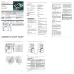
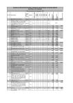
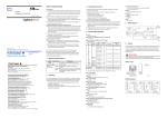
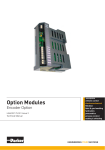
EA15A2
Generator Automatic Voltage Regulator
Operation Manual
Self Excited Automatic Voltage Regulator
15Amp AVR For General Generators
1. INTRODUCTION
Sensing Input
Voltage
Frequency
Power Input
Voltage
Output
Voltage
Current
Resistance
190 ~ 500 VAC, 1 phase 2 wire
Jumper selectable
50 / 60 Hz, Jumper selectable
Thermal Drift
0.03% per °C change in AVR ambient
External Volts Adjustment
± 15% with 5K ohm 1 watt trimmer
100 ~ 300 VAC, 1 phase 2 wire
Unit Power Dissipation
Max. 10 watt
Max. 90 VDC @ 240 VAC input
Continuous 15A
Intermittent 20A for 10 sec
Min. 9 ohm
ADD 150k ohm 4 watt resistor
for 4 ohm exciter field resistance
Under Frequency Protection ( Factory Setting )
60 Hz system presets knee point at 55 Hz
50 Hz system presets knee point at 45 Hz
Voltage Regulation
< ± 0.5% ( with 4% engine governing )
Voltage Build-up
Residual voltage at AVR terminal > 5 VAC
Soft Start Ramp Time
2 sec.
Dimensions
150mm L * 100mm W * 64mm H
Weight
600g ± 2%
2. WIRING ( Refer to Fig4, Fig5 )
2.1 Terminals F+ & F–
3. NOTICE OF USE
● The DC output port of the regulator.
The EA15A can be mounted in various place, like
generator control panel, switchgear cabinets, ect.
But prevent high temperature, high moisture, or
severe vibration places.
● F+ is positive normally connected to the field of
generator marked ‘F+’ , ‘F1’ or ‘J’.
● F− is negative normally connected to the field of
generator marked ‘F–’ , ‘F2’ or ‘K’.
See figure 1 for mounting dimensions.
2.2 Terminals VS & VS
The EA15A surface temperature will be over 60°C
when operations. DO not touch the heat sink.
The power and sensing port of the regulator
( Sensing voltage had been setting on 220V, if you
need another voltage input, please select the
correct input terminal that you want.)
3.1 Startup Procedure
2.3 Terminals VR & VR
1. Ensure all the wire of the regulator are correctly
connected and the proper fuse (15A250V) is
installed.
For external voltage adjustment if required.
2. Turn voltage potentiometer full anticlockwise
( lowest voltage level ).
2.4 Terminals 50 & COM
3. If used, turn external voltage potentiometer to the
middle position.
● Under frequency protection selection.
● Connect a jumper from COM to the 50Hz terminal
for 50 Hz operation, or leave the two terminals
unconnected for 60Hz operation.
4. Turn stability potentiometer
( highest stability level ).
full
clockwise
5. Connect a 110VDC meter across the field with
proper polarity.
______________________________________________________________________________________
2
EA15A
6. Connect a 300VAC meter across line to neutral
7. Start and run the generator at no load and rated
speed.
of generator.
response time If rotated too for CCW, the
generator voltage my oscillate (hunt).
The generator output voltage should build up to a
minimum level if the voltage does not build up, It
may cause by low residual voltage of generator.
Refer to field flashing section in generator
manual.
3. Rotated the front panel STAB control CCW until
the system start oscillating and then rotate cw
just past the point where oscillation occurred.
8. Slowly adjust voltage potentiometer until the
generator voltage reach the proper value.
9. Turn the stability potentiometer clockwise until
instability is shown, and then turn it anticlockwise
slightly still both meter mention in (5) and (6)
shown stable.
10.Interrupt regulator power for a short time
(approximately 1 to 2 second). If the voltage still
stable, the adjustment is now completed.
Otherwise increase the stability slightly, repeat
procedure (10) until stability is reached.
4. ADJUSTMENTS
4.1 Frequency Roll-Off Adjustment
● Connect a jumper from COM to the 50Hz terminal
for 50Hz operation, or leave the two terminal
unconnected for 60Hz operation.
4.4 Droop Adjustment
The droop adjustment allows for adjustment of the
amount of droop which will occur in the generator
output voltage for a given amount of reactive load
current. A CT should be selected which will supply
the A.V.R with 3 to 5 amperes of current with rated
load and power factor on the generator. With 5
Amps of current supplied by the CT, at 0.8 power
factor, the amount of droop can be adjusted from 0
to 6% of nominal generator voltage.
5. FIELD FLASHING
When the regulator is operated with the generator for
the first time, the polarity of residual magnetism may
be reversed or too small to achieve the necessary
build-up voltage for the regulator. If reversing the field
connections does not induce build-up, and the residual
voltage is less than the specified value of 5 Vac, shut
down the Prime-mover and proceed with the following
steps :
● To reset the frequency roll-off, proceed as follow :
1. Startup engine and build voltage.
2. Adjust the prime mover RPM to the desired
frequency compensation ( corner frequency roll
-off) point.
3. Adjust the front panel FREQ control until the
output voltage low about 5V than nominal
voltage. ( For 50Hz applications, the frequency
“roll-off” is factory preset to 45Hz, for 60Hz
operation, the frequency is 55Hz ).
4.2 Voltage Adjustment
1. Adjust the front panel VOLT to vary the generator
nominal voltage.
2. If used, a 5000Ω 1watt potentiometer may be
connected to terminals VR and VR, refer to
Figure4,5.
1. With the Prime-mover at rest and the regulator’s
field output wires disconnected, apply a DC
source ( NOT grounded ) of not more than 3~12
Vdc with Positive to F+ and Negative to F-, in
series with a current-limiting resistor of 3~5 ohms
20 watt. ( The set battery is a suitable source.)
2. Allow approximately 3 seconds before removing
the DC source.
3. With the voltage regulator disconnected ( wires 3
and 4 ), start the prime mover and measure the
“ Residual ” voltage available at the auxiliary
winding. If this voltage is greater than 5 Vac,
reconnect voltage regulator, and voltage build-up
should be successful. If less than 5 Vac is
measured, repeat field flashing procedure.
4. If repeating steps a. and b. does not result in
generator voltage build-up, and residual is
greater than 5 Vac, replace voltage regulator.
4.3 Stability Adjustment
1. Adjust the front panel STAB control the system
stable.
6. PARALLEL FUNCTION
6.1 Parallel Compensation
2. Rotation of the front panel STAB control in the
counter-clockwise (CCW) direction will speed
1. When it is required to operate the regulator in
parallel with an isolated or utility bus, in addition
______________________________________________________________________________________
EA15A
3
to the regulator provisions, a 10VA current
transformer (CT) is required ( See Figure 6 ). The
CT is connected in a generator line and should
deliver from 3 to 5 ampers secondary current at
rated load.
2. The phase relationship of CT signal to the
regulator sensing voltage must be correct or the
system will not parallel properly. The CT must be
installed in the line of the three phase generator
that does not supply sensing to the regulator.
3. Figure 6 shown the correct CT polarity for R.S.T
phase rotation sequence. If the phase rotation
sequence is R.S.T, the CT’s secondary leads
must be interchanged.
6.2 Reactive Droop Compensation
1. For reactive droop compensation, connect the
CT to it’s respective regulator as shown on
Figures 6.
2. A unit-parallel switch shorts the parallel CT
secondary to prevent any droop signal from
being injected into the regulating system during
single unit operation. The switch may not be
required on parallel droop compensation
applications where a voltage drop is not
objectionable.
100
80
50HZ
60HZ
60
40
20
0
10
20
30
40
50
FREQUENCY (HZ)
Frequency Compensation Curves
Figure 2
60
120
100
( % OF MONINAL)
GENERATOR OUTPUT VOLTAGE
120
( % OF MONINAL)
GENERATOR OUTPUT VOLTAGE
Outline Drawing
Figure 1
80
60
40
20
0
1
2
SOFT START (V/Sec)
Soft Start Curve
Figure 3
______________________________________________________________________________________
4
EA15A
CONNECT "CC" TO "380V" THEN
SENSING VOLTAGE IS 380V
WHEN SENSING VOLTAGE IS 220V THEN
MUST CONECT "CC" TO "220V"
AND VF MAY PARALLEL TO VS
(80%~125%)
CONNECT "CC" TO "440/480V" THEN
SENSING VOLTAGE IS 440 OR 480V
(80%~125%)
No Current Compensation Diagram
Figure 4
CONNECT "CC" TO "380V" THEN
SENSING VOLTAGE IS 380V
WHEN SENSING VOLTAGE IS 220V THEN
MUST CONECT "CC" TO "220V"
AND VF MAY PARALLEL TO VS
(80%~125%)
CONNECT "CC" TO "440/480V" THEN
SENSING VOLTAGE IS 440 OR 480V
(80%~125%)
Current Compensation Diagram
Figure 5
7. TROUBLE SHOOTING
SYMPTOM
Voltage does not
build up
Out voltage low
Out voltage high
Out voltage instable
CAUSE
CORRECTION
Residual voltage below 5VAC
Flash generator field with proper method
Incorrect wiring
Check wiring diagram for proper connection
Power/sensing or field wires not
connected
Connect the wires properly
Generator not up to speed
Increase generator speed
Over-excitation
Restart the generator
Poor adjustment is made
Read start procedure carefully and adjust again
Frequency roll-off
Increase generator speed
Incorrect voltage selection
Read user’s manual to select correct voltage
Poor adjustment is made
Read start procedure carefully and adjust again
Incorrect voltage selection
Read user’s manual to select correct voltage
Poor adjustment is made
Read start procedure carefully and adjust again
Field voltage requirement lower
the rang of regulator
Inquire our distributor to solve
P.S. Please use the fuse of the original plant.
______________________________________________________________________________________
EA15A
5
PARALLEL
SWITCH
PARALLEL
SWITCH
PARALLEL
SWITCH
Note!!
(1) When paralleling over 3 generators, the wire connect show in Figure 6.
(2) The polar of paralleling CT show in Figure 6.
Reactive Differential Compensation Diagram
Figure 6
______________________________________________________________________________________
6
EA15A