1
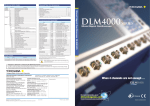
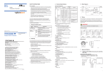
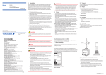
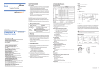
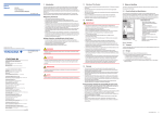
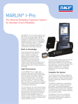
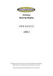
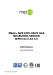
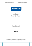
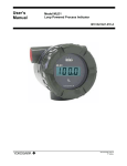
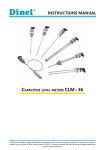
User’s
Manual
YTA50
Temperature Transmitter
IM 01C50C01-01EN
7th Edition: July 2011 (YK)
All Rights Reserved, Copyright © 1998, Yokogawa Electric Corporation
IM 01C50C01-01EN
7th Edition
SAFETY INSTRUCTIONS
3. Handling Precautions
Ex installation:
For a safe installation of YTA50 in hazardous area the following must be observed.
The module must only be installed by qualified personnel who are familiar with
the national and international laws, directives and standards that apply to this
area.
Year of manufacture can be taken from the first two digits in the serial number.
The sensor circuit is not infallibly galvanically isolated from the input circuit.
However, the galvanic isolation between the circuits is capable of withstanding
a test voltage of 500 Vac during 1 minute.
The transmitter must be mounted in an enclosure in order to provide a degree of
ingress protection of at least IP20.
In explosive atmospheres caused by air/dust mixtures:
The transmitter may only be installed in a potentially explosive atmosphere caused
by the presence of combustible dust when mounted in a metal enclosure form
B according to DIN 43729 that is providing a degree of ingress protection of at
least IP 6X in accordance with EN 60529, that is suitable for the application and
is correctly installed.
Cable entries and blanking elements shall be used that are suitable for the
application and correctly installed.
For an ambient temperature ≥60°C, heat resistant cables shall be used with a
rating of at least 20 K above the ambient temperature.
Special Conditions for Safe Use:
If the enclosure in which the transmitter is mounted is made of aluminium and
installed in Zone 0, 1 or Zone 20, 21 or 22 it shall not contain by weight more
than 6% in total of magnesium and titanium.
The additional enclosure of the apparatus shall be designed and/or installed in
such a way that, even in the event of rare incidents, ignition sources due to
impact and friction sparks are excluded.
(1) Read this manual thorughly and carefully before handling the instruments.
Observe the instructions.
(2) Store the product in location that meets the following requirements.
• No exposure to rain or water
• No major mechanical vibration or shock
• Humidity and Temperature limitations
• Ordinary conditions (25°C, 65%) is preferable.
Otherwise, as of specified in “Standard Specifications.”
(3) Avoid corrosive atmosphere for storage and installation.
(4) For safe installation of the transmitter in hazardous area, the following must be
observed. The module must only be installed by qualified personnels who are
familiar with the national and international laws, directives, and standards that
apply to this area.
(5) Yokogawa will not be liable for malfunctions or damage resulting from any
modification made to this instrument by the customer.
The YTA50 is a head mount type of temperature transmitter that accepts
thermocouple or RTD input and converts it to a 4 to 20 mA DC signal for
transmission. The YTA50 conforms to the standard DIN form B head mounting.
It is imperative that usres observe the instructions in this manual to ensure the
protection and safety of operators.
B
T/C
1. Model and Suffix Codes
YOKOGAWA ELECTRIC CORPORATION
5 Bedok South Road, 469270 SINGAPORE
Phone : 65-6241-9933 Fax : 65-6241-2606
YOKOGAWA ELECTRIC KOREA CO., LTD.
14-1, Yangpyongdong-4Ga, Youngdeungpo-Gu, Seoul, 150-866 KOREA
Phone : 82-2-2628-6000 Fax : 82-2-2628-6400
YOKOGAWA AUSTRALIA PTY. LTD.
Tower A, 112-118 Talavera Road, Macquarie Park,
N.S.W.2113, AUSTRALIA
Phone : 61-2-8870-1100 Fax : 61-2-8870-1111
YOKOGAWA INDIA LTD.
Plot No.96 Electronic City Complex, Hosur Road, Bangalore 560100, INDIA
Phone : 91-80-4158-6000 Fax : 91-80-2852-1442
YOKOGAWA CHINA CO., LTD.
3F TowerD Cartelo Crocodile Building
No.568 West Tianshan Road, Shanghai 200335, CHINA
Phone : 86-21-62396262 Fax : 86-21-62387866
50
N
-180 to 1300
100
R
-50 to 1760
200
S
-50 to 1760
200
T
-200 to 400
50
-100 to 900
50
-200 to 600
75
DIN43710
Output Signal
-A . . . . . . . .
4 to 20 mA DC
RTD
CENELEC ATEX (KEMA) intrinsically safe
approval
DC Voltage [mV]
/KS2
FM intrinsically safe/Nonincendive and CENELEC
ATEX (KEMA) intrinsically safe approval
combination
The warranty period of the instrument is as of condition shown when purchasing.
Any trouble arising during the warranty period shall be replaced at free of charge.
The following problems or troubles shall not be eligible of charge-exempt repair.
• Caused by improper usage or storage of the customer which exceeds the
specification requirements.
• Caused by mishandling or modification.
• Caused by fire, earthquake or other acts of God that are not directly a result of
problems of the instrument.
YOKOGAWA ELECTRIC ASIA PTE. LTD.
50
-180 to 1372
Temperature Transmitter (Head Mount Type)
YOKOGAWA EUROPE B. V.
Praca Acapulco, 31 - Santo Amaro. Sao Paulo/SP - BRAZIL
Phone : 55-11-5681-2400 Fax : 55-11-5681-4434
-100 to 1200
K
..........
2. Warranty
YOKOGAWA AMERICA DO SUL LTDA.
J
Suffix code
YOKOGAWA CORPORATION OF AMERICA
Euroweg 2, 3825 HD Amersfoort, THE NETHERLANDS
Phone : 31-88-4641000 Fax : 31-88-4641111
Branch Sales Offices / Wien (Austria), Zaventem (Belgium),
Ratingen (Germany), Madrid (Spain), Runcorn (United Kingdom),
Milano (Italy), Velizy-Villacoublay (France), Budapest (Hungary),
Stockholm (Sweden), Sola (Norway), Warszawa (Poland),
Vila Nova de Gaia (Portugal), Bucharest (Romania), Dublin (Ireland)
50
Model
/DS2
2 Dart Road, Newnan, Georgia 30265-1094, U.S.A.
Phone : 1-800-888-6400 Fax : 1-770-254-0928
200
YTA50
Optional
Specifications
Headquarters
2-9-32, Nakacho, Musashino-shi, Tokyo, 180-8750 JAPAN
Branch Sales Offices
Nagoya, Osaka, Hiroshima, Fukuoka, Sendai, Ichihara, Toyota,
Kanazawa, and Kitakyusyu.
400 to 1820
-100 to 1000
U
Descriptions
Minimum
span °C
E
L
IEC584
Input
ranges °C
W3
+
4 mA
+
-
Accuracy *1
MUX
PGA
A/D
0_16
mA
D/A
EEPROM
2
supply 4–20 mA
A
F01E.ai
Temperature
effect *1
±0.1% or ±2.0°C
±0.1% or ±2.0°C
±0.1% or ±1.0°C
±0.1% or ±0.5°C
±0.1% or ±2.0°C
±0.1% or ±2.0°C
±0.1% or ±1.0°C
±0.1% or ±0.5°C
±0.1% or ±2.0°C
±0.1% or ±2.0°C
±0.1% or ±0.2°C
±0.1% or ±0.1°C
ASTM
E988-90
0 to 2300
200
0 to 2300
200
Pt100
IEC751
-200 to 850
25
Ni100
DIN43760
-60 to 250
25
-10 to 800 mV
5mV
±0.1% or ±0.01mV ±0.1% or ±10µV
0 to 5000Ω
30Ω
±0.1% or ±0.1Ω
6. Wiring
See wiring diagram. For output signal, use twisted pair or cables with performance
equivalent to 600V vinyl insulate cable. For wiring in high or low temperature, use
a wire or cable suitable for such temperature. Use cables and wires which meet
atmospheric conditions. Take necessary measure to avoid corrosion or damage of
cables and wires.
IMPORTANT
When mounting on a sensor head, do not overtighten the screws.
n Dimensions
1
Unit: mm
(Approx. inch)
2
±0.1% or ±0.1Ω
6
*1: The value whichever is greater. value in % indicates the % of span.
Power Supply Effects
±0.005% of FS per Volt
RFI Effects
Tested per EN 61326, field intensity up to 10 V/m.
EMC Conformity
EN 61326
Maximum Zero Offset
±50% of the maximum temperature
Input Signal Source Resistance (for T/C input)
10 MΩ, or 3 kΩ at power-off
Input Lead Wire Resistance (for RTD input)
5 Ω per wire or lower
Burnout
High (21.6 mA or more) or Low (3.6 mA or less)
Output
Two wire 4 to 20 mA DC
Response Time
1 to 60 sec (as specified upon shipment)
Ambient Temperature Limits (Option code may affect limit.)
–40 to 85°C (–40 to 185°F)
Ambient Humidity Limits
5 to 90% RH at 40°C (104°F)
Supply Voltage
7 to 35 V DC
7 to 30 V DC for Intrinsically safe type
Comm.
CPU
Int.
CJC
4
-
3
W5
Resistance [Ω]
supply +
1 7–35VDC
mV RTD.lin.R TC
-Wire
4 3 2
6
mV
Accuracy
See table in the right.
Cold Junction Compensation Accuracy (For T/C only)
±1°C (±1.8°F)
Ambient Temperature Effects (per 10°C Change)
See table below
Standard
5. Block Diagram
5
4. Standard Specifications
Type
Load Resistance (Limitation)
0 to (E–7)/0.023 [Ω], where E is power supply voltage.
Ex. 739 Ω max. @ 24 V DC
Isolation
Input/output isolated to 1500 V AC.
Mounting
DIN form B head mounting
Terminals
M3 screws
Weight
50 g (0.11 lb)
ø6
(0.24)
4
5
3
20.2
(0.80)
33 (1.30)
ø44 (1.73)
F02E.ai
n Wiring Diagram
1
2
3
4
5
6
(+)
SUPPLY
(–)
(–)
(+)
T/C or
DC milivolts
1
2
3
4
5
6
(+)
SUPPLY
(–)
(B)
(A)
Two-wire
RTD or ohm
1
2
3
4
5
6
(+)
SUPPLY
(–)
(B)
(B)
(A)
Three-wire
RTD or ohm
1
2
3
4
5
6
(+)
SUPPLY
(–)
(B)
(B)
(A)
(A)
Four-wire
RTD or ohm
F03E.ai
June '10
1
7. Approval Options
CENELEC ATEX Intrinsically safe model (/KS2, /DS2)
ATEX Certificate: KEMA 06 ATEX 0191
Applicable Standard: EN 60079-0: 2006, EN 60079-11: 2007, EN 60079-26: 2007,
EN 61241-0: 2006, EN 61241-11: 2006
II1G Ex ia IIC T4 or T6, II1D Ex iaD
[ Installation diagram ]
Hazardous Area
Zone 0, 1, 2, 20, 21, 22
Non-hazardous Area
1+
6
T4: -40 ≤ Ta ≤ 85°C
T6: -40 ≤ Ta ≤ 60°C
5
4
Terminal: 3, 4, 5, 6
Uo: 9.6 VDC
Io: 25 mA
Po: 60 mW
Lo: 33 mH
Co: 2.4 μF
2-
3
YTA50
Barrier
Terminal: 1, 2
Ui: 30 VDC
Ii: 120 mA
Pi: 0.84 W
Li: 10 μ H
Ci: 1.0 nF
F04E.ai
Intrinsically safety rating (maximum value)
Supply/output circuit: Ui=30 V, Ii=120 mA, Pi=0.84 W, Ci=1 nF, Li=10 μH
Sensor circuit: Uo=9.6 V, Io=25 mA, Po=60 mW, Co=2.4 μF, Lo=33 mH
Applicable in Zone
0, 1, 2, 20, 21, or 22
Maximum Ambient Temperature for gas-proof
For T4: 85°C, For T6: 60°C
Maximum Surface Temperature for dust-proof
For T4: T105°C (Ambient Temperature: –40 to 85°C)
For T6: T85°C (Ambient Temperature: –40 to 60°C)
FM Intrinsically safe/Nonincendive model (/DS2)
Applicable Standard: FM 3600, FM 3610, FM 3611, FM 3810
Installation diagram
[ Intrinsically safe ]
Non-hazardous Location
Hazardous (Classified) Location
Ambient temperature limits
T4: -40 to +85 deg. Celcius
T6: -40 to +60 deg. Celcius
sensor
Class I,Division1, Groups, A,B,C,D
Class II Division 1 Groups E,F,G or
Class I, Zone 0, IIC
6
1+
5
4
YTA50
2-
3
Terminal 3,4,5,6
Only passive, or non-energy
storing devices such as RTD's
and Thermocouples may be
connected.
Terminal 1 , 2
Vmax or Ui: 30 V
Imax or Ii: 120 mA
Pmax or Pi: 0.84 W
Ci: 1 nF
Li: 10 uH
Associated Apparatus
or Barrier
with
entity Parameters:
UM ≤ 250V
Voc or Uo ≤ Vmax or Ui
Isc or Io ≤ Imax or Ii
Po ≤ Pi
Ca or Co ≥ Ci + C cable
La or Lo ≥ Li + L cable
This device must not be
connected to any
associated apparatus
which uses or generates
more than 250 VRMS
[ Nonincendive ]
Non-hazardous Location
Hazardous (Classified) Location
Class I,Division2, Groups, A,B,C,D
Class I, Zone 2, IIC
Ambient temperature limits
T4: -40 to +85 deg. Celcius
T6: -40 to +60 deg. Celcius
sensor
6
1+
Associated Apparatus
or Barrier
2-
Voc or Vt ≤ Vmax
Ca ≥ Ci + C cable
La ≥ Li + L cable
5
4
YTA50
3
Terminal 1 , 2
Vmax: 35 V
Ci: 0 μ F
Li: 10 uH
This device must not be
connected to any
associated apparatus
which uses or generates
more than 250 VRMS
F05E.ai
2