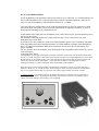
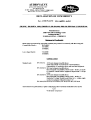
1
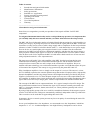
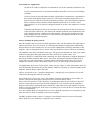
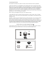
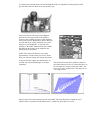
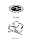
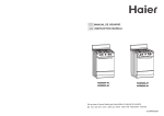
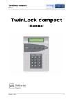
User Manual
for the
RKV - Mark II
tube headphone amplifier
We congratulate you with the purchase of this superb AUDIO VALVE HiFi component.
This handcrafted product has been manufactured according to your wishes,
and will allow you many years of musical joy.
AUDIO VALVE guarantees that this amplifier has been produced under the strictest manufacturing
guidelines, established through decades of tube amplifier design. Your RKV headphone amplifier
has been thoroughly tried and tested in all detail.
I personally guarantee the quality of this product
H. Becker
Manager Production & Development
Table of contents
1.
Introduction and general information
2.
Manufacturers information
3.
Safety precautions
4.
Intended use / Application
5.
Factory assembly & getting started
6.
Operating instructions
7.
Technical data
8.
Use of the Impedancer
9.
Warranty
_____________________________________
1.Introduction and general information
Dear client, we congratulate you with your purchase of this superb AUDIO VALVE HiFi
component.
To safeguard maximum functionality and to avoid problems up operation, it is important that
you carefully study this user manual and that you follow all instructions therein precisely!
The RKV Mk II excels through a number of technical details that are unique for a tube based device
in this price category. By design only tubes are found inside the signal path of the RKV. Solid state
electronics are only used to create a stable voltage supply and to compensate for the low production
tolerances of tubes. The RKV ist build in double mono, i.e. each channel has its own power supply.
Even in devices at a much higher price range this feature is not a standard. For the technicians
amongst us; the RKV has been build as a differential amplifier, and therefore the output voltage is
always in phase with the input signal. Of course an ALPS potentiometer is used to control volume.
Like all other Audio Valve amplifiers the RKV is build inside a hard-coated case of laser cut steel
with gold-plated terminals. A few important notes:
The most successful Audio Valve tube amplifier is the RKV, that has been launched in 1984.
Traditional tube technology has been discarded and through new and uncommon solutions a
concept has been created, that was and is unique in the construction of amplifiers. However,
modern solid-state technology was not discarded and thus a product was build that reflects 40 years
of electronical development. The concept is copy protected by the patent DE 3200 51T.
Why a headphone amplifier? Can't we simply use the output of a receiver? The answer is a clear
NO. To faithfully reproduce the extreme dynamic range that modern CD-players allow, high quality
dynamic headphones need driving voltages that are much higher than those provided by the power
supplies of transistor devices. To allow adequate output levels was one of the requirements for the
new amplifier. In addition short-circuit protection and a technically impeccable reproduction with a
typical tube sound were major design goals. All these requirements were fulfilled with the RKV.
The concept of the RKV has no output transformer. It is a typical example of an OTL design. The
only problem that remained was to eliminate the signs of wear and tear normally associated with
tubes, e.g. increasing tolerances, humm, microfonie, etc. These problems generally take a lot of
effort to deal with.
By using a high-quality opamp a DC-servo could be created that eliminates all the negative aspects
of tubes. Even the base line settings are automatically stabilised, independent of the age of the tube.
Thus even tubes can be used that are approaching their end of life.
In summary, the servo control system prevents any losses in quality of sound during the entire lifetime of the tubes.
In case your headphone has a low impedance, we recommend to use the "Impedanzer" which has
outputs for 8 - 16 - 32 - 64 Ohm headphones. Also high-efficiency loudspeakers can be driven.
2. Manufacturers information
Factory address:
AUDIO VALVE, H. Becker,
Auf dem Streken 7
D-32689 KALLETAL
GERMANY,
Tel.:
Fax:
0049 - (0) 5264 77 99
0049 - (0) 5264 65 44 77
VAT.-ID.
125 673 965
Email:
website:
[email protected]
www.audiovalve.de
3. Safety precautions
Important: Please read the user manual before assembly and operation of the amplifier
Anyone, unable to comprehend the instructions stated in the user manual should not operate the
device.
Children and minors are not to use the device and should be kept at a safe distance from the device
while it is running.
The user is responsible for operating the device in an appropriate fashion and takes full
responsibility towards third parties. At first use electrical safety is to be checked through
professional assessment
Please check that the mains voltage printed on the rear panel of the amplifier corresponds with the
mains voltage in the country where you intend to use the amplifier.
Always check powercords and plugs for damage before use.
Disconnect the powercord before any service to the amplifier.
In the unlikely event of a failure of the device repairs may be performed by AUDIO VALVE
authorized technicians only.
Use ORIGINAL spare parts only!
Please take note of the fact that we decline product liability for damages caused by our devices,
parts and components as a result of:
a) Unprofessional and/or faulty and/or correct repairs that have been performed in other than
the by AUDIO VALVE approved repair facilities,
b) Usage of other than ORIGINAL and approved spare parts.
The RKV-Amplifier is subject to and complies with German security class 1 for devices with metal
housing. The device is grounded, and may not –by manipulation or otherwise- be ungrounded for
any reason! To prevent humm as a result of ground loops the electrical circuitry internally has been
disconnected from grounded mass!!
4. Intended use / Application
AUDIO VALVE Hi-Fi Amplifiers are intended for use for the situations listed below only:
-
To play and transfer music of any make and fashion when this occurs in private dwellings
or studios.
-
All devices must be operated under moderate climatological circumstances, comparable to
those under which human beings usually live. When the surrounding temperature is too
high, the device will heat up beyond its optimal parameters. This can damage the amplifier.
Proper ventilation will be needed, and the amplifier should not be covered in. Allow
approximately 3 cm of air sidewise and approximately 4 cm above the amplifier to cool the
amplifier.
-
Unusually high humidity of the air increases the risk of shortcircuits in the device because
of the increased conductivity. This reduces the internal insulation values dramatically and
will eventually result in a malfunction of the amplifier. This increased conductivity also
might endanger the user of the device. In general terms the amplifier should not be used
for other than its intended purpose.
Factory assembly & getting started
Once the amplifier has arrived at its desired destination, make sure the amplifier has ample time to
adjust to the climate at its new location. It is likely that the changes in temperature and humidity
between the last location and the new one, has caused condensation to build up somewhere in the
amplifier. This can damage the device. Please allow the amplifier at least two hours to acclimatise.
The amplifier comes fully assembled, ready to go. The powercord should not be used as yet, please
connect all other input and output connectors first (cinch cables, speaker cables, etc).
The decive MUST be switched off while connecting it to other components, it might be damaged if
this is done with the amplifier under power. The person operating the amplifier might be hurt as
well in this case, since powerspikes, operating currents and voltage charges may occur! Check
whether the ON/OFF switch is in the OFF position. If so, you can now plug in the powercord.
Use high quality cables only! Usage of DIY cables, low spec cables or cables intended for other use
voids all warranty and cancels any product liability. Make sure all plugs are connected tightly to the
amplifier. When in doubt, replace the cable.
Allways use the device in a ’complete configuration’ , damages may occur when devices are not
connected to the amplifier when it is being run.
Never lift the device by its glass cover. The amplifier should be positioned at a level surface, in
time the construction of the glass housing may fail as a result of tensile forces.
Please check all connectors. If all connectors are undamaged, make sure the switch is in the OFF
position, connect the powercord and swith the amplifier on. You can make sure the amplifier is
properly connected by checking the tubes and the blue LED at the front of the amplifier. Only the
inside of each tube should glow. If the steel coverjacket glows as well, the device is faulty and must
be serviced immediately.
As a rule of thumb the device should work now. Don’t push the volume up to its maximum yet and
allow the device to burn in smoothly and avoid powerspikes.
The RKV-Amplifier needs at least a 10 Ampere circuit breaker between its powercord and the
mains. Make sure your wallsocket is equiped in such a fashion.
6. Operating instructions
The frontside of the RKV has a number of controls, whose functions need some explanation.
At the left you find two 6.3 mm headphone jacks. Internally these jacks are connected in parallel.
Both can be used to connect headphones with an load impedance of 100 - 2000 Ohm. Please do not
connect devices with a lower impedance, the output of the amplifier is "shortened " and the life time
of the tubes is reduced drastically. You may also connect an impedanzer to one of the headphone
jacks which allows you to use low impedance headphones. Please do not connect an additional
headphone in case the impedanzer is used. It might be forgotten and be loaded with an uncontrolled
high output level. This could damage the heaphone.
Please connect your headphone to the jacks at low sound levels only.
At the middle of the front you find the ALPS potentiometer to control volume. It has a 51 kOhm
impedance which is at the same time the input impedance of the amplifier. The potentiometer has a
logarithmic scale.
The RKV is capable of extremely high sound levels. This has the danger of severe hearing damage.
While listening to headphones we lack several feedback mechanisms on volume level that are
present when we listen to loudspeakers. Much less distortion, no feeling of the lower frequencies by
our body and no psychological restraints not to annoy our fellow-men easily seduces us to listen at
volume levels that are detrimental to our hearing. Hearing damage from regular exposure to high
sound levels progresses slowly but is irreversible and can result in permanent hearing loss.
!! Please choose your volume setting with caution !!
At the right side of the front the power switch and the power indication LED are found. The blue
LED is lid with the power ON and mutes as soon as you switch the amplifier OFF.
Headphone
Main Power
Right
Left
Input
Volume
The black jack at the upper left of the backside is the IEC power inlet. Inside the power inlet a fuse
can be found as a protection against overload.
For the 117 V version the value of the fuse should be 1 Ampere Slow.
For the 235 V version the fuse is 0,63 Ampere Slow.
Please only change the fuse with the powercord disconnected and if you're sure that the amplifier is
not defective!
Below the power inlet you find two pairs of RCA-inputs to connect the source of your audio signal.
The two pairs of inputs are connected in parallel. Thus you can bypass the input signal to another
amplification or recording device. Please use either the lower or the upper pair of RCA-inputs to
connect your source.
Whenever the device is to be serviced, please disconnect the powercord. Only a knowledgable
technician should have access to the amplifier.
This survey of the PCB's will explain the most important elements for service.
The four tubes are all equal and of the type PCL 805. Thereby the amplifier is relatively secure
from overload. The two tubes at the left side belong to the same audio channel.
To be mentioned are 4 fuses for the two mono channels. The 0.5 Ampere fuses are for the anodal
current regulation and the large 3,15 Ampere versions protect the heating circuitries. Normally,
these fuses will hardly fail, as the inrush current at power ON is reduced to acceptable levels by a
guarding circuitry. In case a fuse is to be exchanged, please make sure you use the same value and
not a higher one.
If you want to exchange tubes, please disconnect the power cord. Also make sure that all pins are
properly mounted into the sockets. It is not uncommon that a pin is bend and doesn't enter the
socket.
7. Technical data:
•
•
•
•
•
•
•
•
•
•
•
•
•
•
•
OTL - transformer outless tube amplifier
double mono construction
Alps volume control
2 stereo jackets 6,3 mm for headphones
tubes: 4 * PCL 805 (PCL 85 or 18 GV 8 - german old TV "vertikal" ampl. tube )
power output: each channel 3 watt SINUS, ( between 100 and 400 ohm loads )
bandwidth: 15 - 100 000 hz
damping factor: 3600 !
distortion 0,002 % at 1 Watt-200 Ohm load
maximum output voltage 80V
IC - fullautomatically - controlled bias
class-A
power consumption 60 watt
size 360*200*120 mm (d.w.h.)
weight 7.2 kg
•
more interesting links example in : www.head-fi.com
A softstart prevents high initial currents through the cold, low impedance, heating element. This
prevents the element to break at its most narrow spot.
Of special interest with respect to headphone
protection is the suppression of all amplifier
activity at the warming up phase of the amplifier
and at power-down. During these phases charging
currents and large voltage variations may cause
damage to your headphone. To prevent such
damages a „BLOOB“ Eliminator has been added
that shortens the outputs of the amplifier and
thereby protects the phone.
NOTE: The output will become active after
approximately 1 minute after power ON. Please
keep your volume settings low during this period.
At power OFF the outputs are shortened for 10
seconds only. Internal discharges are by then
completed.
The picture shows the fuses and their values for
one audio channel. In case of a defect they have to
be exchanged by versions of the same value. The
lower one is 0,63 Ampere Slow. The upper one is
3,15 Ampere Slow
These pictures show the distortion spectra of the RKV. The main distortion component is K2,
which results in a pleasent sound characteristic, if audible at all at these low levels.
8. Use of the IMPEDANZER
In case headphones with impedances below 100 Ohm are to be connected, it is recommended to use
the so-called Impedanzer for a better match between amplifier and load impedance. This device
allows to connect headphones with impedances between 8 – 64 Ohm.
Also high efficiency loudspeakers can be connected through the two pairs of connectors at both
sides of the front. The rotary switch selects the right amount of impedance matching. In case of
doubt optimal matching can be established by ear.
At the middle of the front plate two headphone jacks can be found. Again, optimal matching can be
selectec by the switch.
The backside of the Impedanzer has a cable connector that is to be connected to one of the
headphone jacks of the RKV.
If you like to use two headphones of the same load impedance please select a matching impedance
at the Impedanzer that equals half the impedance of each headphone. Example: Both headphones
have a 32 Ohm load impedance and both are connected. Please select the 16 Ohm setting for a
proper matching.
The two pictures show the frontplate and a photograph of the Impedanzer and visualize the various
control elements.
(Upgrading Febr. 2004)
The Impedanzer is equipped with a bypass switch that completely removes the built-in transformer from the
circuit, a so-called true bypass. This feature allows the RKV owner to hook up headphones such as the AKG
K-1000 directly to the speaker binding posts of the Impedanzer using the headphone's standard cables and
without any need for custom terminations. At the same time the RKV's output impedance remains
unchanged, resulting in a perfect impedance match between RKV and headphone.
When the bypass switch is facing upwards, the Impedanzer's impedance selector is activated and may be
adjusted to loads of 8, 16, 32 and 64 Ohms. When the bypass switch is facing downwards, the impedance
selector is bypassed, and the RKV will work best into loads of approximately 100 Ohms or higher.
A word of warning: The volume control of the RKV should always be turned all the way down before
operating the bypass switch. Bypassing the Impedanzer will otherwise result in a considerable jump in
volume, which may damage your hearing or your equipment.
RKV- Mark II impedancer
16
32
8
Speaker
64
Ohms
Speaker
PRE AMPLIFIER
RKV
Mark II
Voltage
V~ 50/60Hz
VA Si
WARRANTY
AUDIO VALVE warrants its components for a three-year period on all electronics and a 90-day
period on the tubes from the purchase date.
In the event of a failure of your amplifier , AUDIO VALVE will repair or readjust this unit or ,
should the occasion arise , will replace it provided that all conditions stipulated in this warranty are
met.
In order to initiate service of any kind it is necessary to obtain distributor or dealer authorization
prior to shipping the unit for service.
Any of the following conditions shall void the warranty:
•
Operation not in accordance with this manual.
•
Abuse , accidental damage or unauthorized modifications , as determined by AUDIO VALVE
or its agents exclusively.
•
Removal , defacing or falsifying of the serial numbers.
•
Shipping without the original complete factory crates.
WARRANTY REGISTRATION
Please fill out and return this warranty form to the distributor within 15 days of the purchase
date, or visit the AudioValve homepage for ONLINE warranty registration (its cheaper and
faster)
•
MODEL : _______________________________________________
•
SERIAL NUMBER : _______________________________________
•
PURCHASE DATE : ______________________________________
•
AUTHORIZED AUDIO - VALVE DEALER:
•
PURCHASER`S NAME : ___________________________________
•
STREET ADDRESS : ______________________________________
•
CITY : __________________________________________________
•
ZIP / POSTAL CODE : _____________________________________
Send to :
AUDIO VALVE, H. Becker,
Auf dem Streken 7
D-32689 KALLETAL
GERMANY,