1
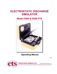
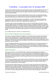
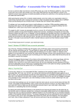
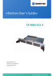
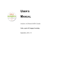
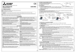
Journal of Network and Computer Applications (1996) 19, 405-413
A microcontroller based pacemaker tester
D. Radhakrishnan
Division of Computing Systems, School of Applied Science, Nanyang Technological University,
Nanyang Avenue, Singapore 639798
The design of a microcontroller based pacemaker tester is presented in this paper. Both invasive and noninvasive (transthoracic) pacemakers can be tested using this device. Two test loads are provided; a 500
ohms load for testing invasive pacemakers and a 50 ohms load for testing non-invasive pacemakers. A
two line LCD display is used to indicate the test parameters, test results and the test in progress. The test
results can be conveniently transferred to a PC or to a printer through the RS232C serial port provided. The
unit can be packaged inside a small package and hence can be used as a handheld tester.
1.
Introduction
Electrocardiogram (ECG) is one of the common tools used today for the diagnosis of a large
number of diseases. The number of heart patients is growing at an enormous rate each year. The
use of pacemakers (external and implanted) to correct any malfunctioning of the heart is a very
common practice among cardiac patients. Since a pacemaker is a very crucial device, the
importance of its testing and calibration need not be overemphasized. The pacemaker tester
described in this paper can be used to test a large variety of external pacemakers used today.
Since the range of parameters and complexity of operation varies considerably among different
manufacturers, it is a very difficult task to integrate all these requirements into a single tester.
The design of pacemaker testers must be made based on easily available components. The
selection of a specific microcontroller plays a major role in the design. Since the pacer widths of
earlier pacemakers were below 1MS, analog-to-digital converters (ADC) must be carefully
selected to provide the required accuracy. The overall cost of the system must also be a major
consideration.
2.
Terminology
The different parameters related to pacer pulses are given below.
•
Pacer rate is the number of pacer pulses delivered per minute (PPM) by the pacemaker.
•
Pacer Width is the duration of a pacer pulse (MS).
•
Pacer Amplitude is the current delivered by the pacemaker at a particular output setting.
•
Refractory period is the time interval during which the pacemaker is insensitive to any
external inputs. If a QRS is detected during this period, the pacemaker ignores it. On the
otherhand, if a QRS is detected outside the refractory interval, then the pacemaker resets its
internal timer and the next pacer pulse is generated after a delay of one period from this QRS
wave. There are two refractory periods; pacing and sensing.
405
Journal of Network and Computer Applications (1996) 19, 405-413
•
Pacing Refractory period is the maximum time interval after the generation of a pacer pulse
during which time the presence of a QRS wave is ignored by the pacemaker.
•
Sensing Refractory period is the maximum time interval after a QRS wave is sensed by the
pacemaker during which time the presence of a second QRS wave is ignored.
•
Sensitivity is the minimum QRS amplitude required to cause the pacemaker to operate in the
demand mode. (A QRS wave of this amplitude will be sensed by the pacemaker.)
•
A-V delay is the interval between an atrial stimulus and the subsequent ventricular stimulus.
•
Noise Immunity is the maximum amplitude of noise signal that will not affect the correct
performance of the pacemaker.
A few pacemaker testers are available in the market today [10-11]. These testers are equipped to
measure the above mentioned parameters. But none of them have the capability for automatic
measurement of any of the above test parameters. For example, the measurement of pacing
refractory period is carried out by manually selecting different time intervals on the tester and
continuously monitoring the pacemaker until an appropriate response is received. The last tester
setting gives the pacing refractory period. On the otherhand the tester described in this paper
measures each test parameter automatically without any manual intervention.
3.
System Design
A block diagram of the pacemaker tester is shown in Figure 1. The microcontroller houses the
program and controls all peripherals. The external static RAM stores all the data collected during
the normal test operation and is also used as temporary storage during floating point calculations.
The pacemaker output directly feeds into an input selection logic network which selects the test
load using a multiplexer (MUX) based on the manufacturer’s specifications. The output of this
network feeds into an ADC for converting the analog signals into digital data for subsequent
processing. The digital data output of the ADC is saved in the RAM. A digital-to-analog
converter (DAC) is used to generate different test waveforms for the pacemaker. An LCD display
is used for menu display and output indications. The keypad selects the particular test to be
performed. The power supply unit provides regulated ±5V dc for the whole system and +2.5V
dc to the reference inputs of ADC and DAC. This power is derived from a 9V dc battery using a
charge pump and a few voltage regulator chips.
3.1
Microcontroller
The microcontroller selected is a derivative of the well-known 80C31: the Philips 80C52 [1].
This is an 8 bit microcontroller which contains an 8kx8 ROM, a 256x8 RAM, four 8-bit ports
(P0, P1, P2, P3 ), three 16-bit counters/timers, a six-source, two-priority level
406
Journal of Network and Computer Applications (1996) 19, 405-413
Figure 2. Microcontroller, Address Decoder and Control Signals
nested interrupt structure, a serial I/O port, and on-chip oscillator and clock circuits. The main
program is written in assembly code and the compiled code is stored in the internal ROM. The
program code depends on the different measurements to be carried out.
The Ports P2 and P0 are used as address and data busses respectively. Port P1 is used for
controlling the keypad and Port P3 is used for controlling the analog-to-digital converter (ADC).
An 8 bit latch L2 is used for generating extra control signals for the LCD display, digital-toanalog converter (DAC) and the multiplexer (MUX). A simple RC circuit is used for initializing
407
Journal of Network and Computer Applications (1996) 19, 405-413
the microcontroller on power up (RST) as shown in Figure 2. A good choice is R=10k and
C=10uF. A crystal of 11.0592 MHz is a good choice for clock frequency. An 8 bit latch 74C373
(L1) is used for latching the lower order address byte from P0 bus. The higher order 8 bits of the
address is available directly from P2 port. A 3X8 address decoder is used to generate the chip
select (CS) signals for the different devices in the tester. The CMOS decoder 74C138 is used for
this purpose. The 3 enable signals together with the 3 address lines in ‘138 can be carefully
selected to generate the proper decoder outputs. The RXD (P3.0 ) and TXD (P3.1 ) leads can be
used to transfer data to a PC through an RS232C interface.
Figure 3. Input Selection Logic and Analog-to-digital Converter
3.2
Input Selection Logic
The pacemaker output leads feed directly into the input selection logic. For normal testing these
outputs are connected to the “Ventricular input” leads of the tester as shown in Figure 3. The
“Atrial input” leads are connected to the “Atrial output“ leads on the pacemaker during A-V
delay measurement. The input network is responsible for the selection of different loads to be
connected to the pacemaker and also for amplifying the pacer pulses before feeding to the input
of ADC. Two loads are provided; one a 50Ω and another 500Ω. Invasive pacemakers are always
tested using the 500Ω load and non-invasive ones using the 50Ω load. A slide switch S1 is used
for selecting the load. When S1 is open, the load seen at the ventricular input leads is 500Ω,
otherwise 50Ω ( for transthoracic pacemakers). In transthoracic pacemakers the current level
could go to as high as 200mA. Hence an input attenuation network is included to scale down the
voltage. This attenuation network feeds into a dual channel multiplexer (DG409). The scale
factors used are 1:10 and 1:100 at X0 and X1 inputs of the MUX. Similar attenuation values are
provided on the atrial pacer input leads for X2 and X3 respectively.
The MUX output is amplified by a differential amplifier (gain ≅ 10) before feeding to the
analog-to-digital converter.
408
Journal of Network and Computer Applications (1996) 19, 405-413
3.3
Analog-to-digital Converter (ADC)
An 8 bit parallel analog-to-digital converter (ADC1205) is used for converting the pacer signal to
digital data. The ADC control leads (WR, RD, INT, STS, and CLK) are fed from the
microcontroller. The chip select (CS) line is controlled from the address decoder logic. The ALE
output of the microcontroller feeds the clock input (CLK) to ADC. The frequency of this signal is
1/6 of the microcontroller clock frequency. The data output lines are tied to the data bus on the
microcontroller.
Figure 4. Waveform Generator using Digital-to-analog Converter
3.4
Digital-to-analog Converter (DAC)
A dual channel 8 bit DAC (AD7528) is used to generate the test waveforms Sine (SIN), Square
(SQR), and Haversine (SSQ) as shown in Figure 4. Three separate look-up tables are used to
store these waveforms. The SQR and SSQ waveforms are used to test the sensitivity of the
pacemaker as well as its refractory period. The SIN waveform is used for testing the noise
immunity. Of the two channels in the DAC one of them is used to control the amplitude of the
generated waveform (Channel A). This allows 256 different amplitude selections for the
waveform.
4.
Test Generation
A comprehensive set of tests for the pacemaker include the measurement of pacer amplitude,
pacer width, pacer rate, refractory periods, sensitivity, A-V delay and noise immunity. In fact, the
pacemaker must be tested for its full range of parameter values as specified by the manufacturer.
Hence for example, pacer amplitude measurement must be done under varying test loads at
various current settings, refractory period and sensitivity measurements using signals of varying
shapes, pacer rate at various rate settings and so on. To this end, the individual characteristics and
parameter ranges of different pacemakers are first tabulated [2-9]. A comprehensive set of such
409
Journal of Network and Computer Applications (1996) 19, 405-413
requirements is given in Table 1. This table lists the pacemaker parameter ranges for both
invasive and non-invasive pacemakers. Furthermore Square and Haversine waveforms are
recommended by different manufacturers for testing the refractory periods as well as the demand
sensitivity. Based on the parameter ranges given in Table 1, and the test waveform requirements,
a comprehensive list of tester parameters with appropriate test ranges are identified. This is given
in Table 2.
Table 1. Pacemaker Parameter Test Ranges
Test Parameters
Invasive Pacemakers
Non-invasive Pacemakers
Rate (PPM)
Current (mA)
Load (ohms)
Pacer Width (MS)
Refractory Period (MS)
Sensitivity (mV)
A-V Delay (MS)
50/60 Hz Noise Immunity
30-180
0.1-20
300-1200
0.8-1.8
90-335
1-100
0-300
100mV at max. sensitivity
30-180
0-200
0-1k
20-40
200-340
Table 2. Parameter Specifications for the Pacemaker Tester
Test Parameters
Invasive Pacemaker
Non-invasive Pacemaker
Test Load (ohms)
Amplitude (mA)
Pacer Rate (PPM)
Pacer Width (MS)
Refractory Period/
Sensitivity
500
0.1-25
20-1000
0.8-80
10,25,40,100,200MS
SQ, SSQ Waves
50
1-200
20-1000
0.8-80
10,25,40,100,200MS
SQ, SSQ Waves
4.1
Algorithm
The first requirement in generating an algorithm is to detect the pacer waveform in the presence
of noise signals. This depends on the signal level of the waveform. As the signal level decreases,
detecting the waveform becomes more and more difficult. A three point detection method is used
to detect the presence of a pacer wave. First a minimum signal threshold value is selected so that
when the input level is below (above) this represents the absence (presence) of a pacer wave.
This is fixed based on the minimum pacer amplitude. Once the threshold value is fixed, the
following criteria is used for the selection of the three points.
1. The first point is selected to be lower than the specified threshold value.
410
Journal of Network and Computer Applications (1996) 19, 405-413
2. The second point identifies the starting of a waveform. The magnitude at this point must be
greater than the selected threshold value.
3. The third point is chosen so that the waveform can be separated from transient noise spikes
and also to indicate the presence of a sustained pacer wave. The signal level at this point must be
higher than that for point 2.
Once the pacer is on, the next step is to detect the termination of the pacer. This is achieved
simply by comparing the input signal level with the selected threshold value. Once the signal
level falls below this value the pacer is assumed to have ended. Having detected the occurrence
of a pacer the next step is to perform various measurements. These tests are selected from the
displayed menu using the keypad.
To measure the pacer rate a 1MS timer is started whenever the tester senses the beginning of
a pacer pulse. The timer is stopped at the beginning of the next consecutive pacer pulse. Now a
count of the number of 1MS timer interrupts is a good measure of the pacer rate. One of the
microcontroller timers is used for this purpose.
Pacer width is measured based on the total number of ADC samples while the pacer is on.
Hence pacer width accuracy depends on the sampling rate of ADC.
Pacer amplitude measurement is done by measuring the voltage developed across the
precision load resistance with the pacemaker output current flowing through it. This voltage
when divided by the precision load resistance gives the amplitude.
A-V delay is measured by counting the number of lMS timer interrupts between an atrial
pacer and the subsequent ventricular pacer.
The measurement of paced refractory period uses a few cycles of the pacemaker output. First
the tester measures the pacer-to-pacer interval T. Then it puts out a SQR/SSQ wave 40MS wide
delayed by an interval 'D', which is more than the pacing refractory period, from the last pacer
pulse. The pacemaker senses this wave. The delay time 'D' is then decremented in steps during
every cycle until the SQR/SSQ waveform is not sensed by the pacemaker. The maximum value
of the interval 'D' for which the pacemaker does not sense this wave is the pacing refractory
period.
The sensed refractory period is measured in a similar manner, except that the tester now
generates two SQR/SSQ waves instead of one. The first wave is generated at a fixed delay from a
pacer pulse which is greater than the paced refractory period. The pacemaker always senses this
wave. The second one is generated at a delay 'D' from the first wave. Initial value of 'D' is
selected to be greater than the sensed refractory period. Hence the first time on, the pacemaker
senses both the waves. On subsequent cycles, the delay 'D' is reduced in steps until the
pacemaker is unable to sense the second one. The maximum value of 'D' for which the
pacemaker does not sense the second wave is the sensed refractory period.
For sensitivity measurement also different waveforms (Square and Haversine) are selectable
with widths varying in steps from 10 to 200MS. Once a waveform with a particular width is
selected, the tester first generates this waveform with an amplitude of 100mV irrespective of the
sensitivity control setting and pacer rate control setting on the pacemaker as long as the pacing
rate is set below 150PPM. This waveform is delayed from the pacer pulse so that it is outside the
pacing refractory period. The tester then checks whether or not this wave is sensed by the
pacemaker. If it is not sensed, then, a message "exceeded" is displayed which means that the
pacemaker needs an amplitude more than 100mV for sensing at that setting. If the wave is
sensed, the tester then reduces the amplitude in steps until it reaches the lowest value required for
411
Journal of Network and Computer Applications (1996) 19, 405-413
the pacemaker to sense it. (The algorithm used here converges to the lowest value in the least
number of cycles.) This lowest value is the sensitivity.
Noise immunity measurements are done by feeding sine waveforms at 50 & 60 Hz to the
pacemaker. These waveforms are generated by the waveform generator of Figure 4. During this
test the amplitudes of these waveforms are varied until they exceed the rated noise immunity
level (100mV). The pacemaker sensitivity must be set to its maximum value during this test.
4.2
Auto Test Mode
This is a very powerful feature provided wherein the tests are performed in a semi-automatic
manner without much user intervention. Test and documentation time can be greatly reduced
using this feature. For each parameter being tested, a number of different test values are
preprogrammed in the tester. The user has the option of running all these tests with the given
default values, or running one or more of them with user selectable values, or skipping one or
more of these tests. If the user modifies a value, this modified value can be saved so that it can be
used for subsequent tests as long as the unit is not switched Off. (The user can also leave the
modified value unsaved so that the original default values will be output during subsequent
tests.) The test sequence continues until all the parameters are tested.
Once a test is run on the tester, it stores the measured value for future reference. At the
completion of the test sequence, the results can either be sent to a printer or to a PC through the
RS232C interface. At this time both the set and measured values can be compared and if there is
a mismatch of more than a certain percentage, then a comment to that effect can be printed.
5.
Conclusion
A simple low cost pacemaker tester is presented here. The design is based on the Philips 80C52
microcontroller. All test results are based on three elements, the crystal oscillator, voltage
reference source and the precision load resistance. Time measurements use a lMS timer,
controlled by the crystal oscillator running at 11.0592MHz. Voltage and current measurements
use a precision load resistance and the reference voltage source. The reference voltage source
(Vref) is set at +2.5V dc.
References
1. Philips, 1994. 80C51-Based 8-Bit Microcontrollers, The Netherlands
2. Medtronic 5375 Pulse Generator Technical Reference Manual
3. Medtronic 5880A - External Demand Pacemaker Technical Reference Manual
4. Medtronic 5330 - AV Sequential Demand Pacemaker Technical Reference Manual
5. Medtronic 5345 - DDD Temporary Pacemaker Technical Reference Manual
6. Physio-Control LIFEPAK 9P Pacemaker/Defibrillator Technical Reference Manual
7. HP CodeMaster Defibrillator/Pacemaker Technical Reference Manual
8. MDE Escort 300A Defibrillator/Pacemaker Technical Reference Manual
9. Zoll PD100 Pacemaker/Defibrillator Technical Reference Manual
10. Bio-Tek Pacemaker Tester - User Manual
11. Environics PaceAlyzer PFA-1A Technical Reference Manual
412
Journal of Network and Computer Applications (1996) 19, 405-413
Damu Radhakrishnan received the B.Sc. degree in Electronics and Communication Engineering from the University
of Kerala, India in 1968 and M.Tech. and Ph.D. degrees from the Indian Institute of Technology, Kanpur, India and
the University of Idaho, Moscow, Idaho, USA, both in Electrical Engineering, in 1975 and 1983, respectively. From
1983 to 1985 he was an Assistant Professor in the Department of Electrical Engineering, Old Dominion University,
Norfolk, Virginia and from 1985 to 1990 with the Department of Electrical Engineering, University of Idaho,
Moscow, Idaho. From 1990 to 1994 he served as the Director of R&D at Netech Corporation, New York. Presently
he is with the School of Applied Science at Nanyang Technological University in Singapore. His research interests
include VLSI design, fault tolerant design of digital systems, microcomputer applications and switching theory.
413