1
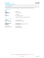
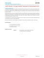
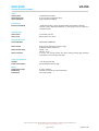
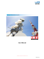
VA-700
Analogue Video Distribution Amplifier
User Manual
IRT Electronics Pty Ltd | www.irtelectronics.com
Revision 09
VA-700
ANALOGUE VIDEO DISTRIBUTION AMPLIFIER
Revision History:
Revision
01
02
03
Date
21/03/1996
02/07/1996
25/07/1996
By
AJP
AJP
AJP
04
05
27/11/1996
12/01/2001
AJP
AL
06
07
05/07/2002
11/09/2002
AL
AL
08
22/10/2010
AL
09
22/05/2012
AL
Change Description
Original Issue.
AVD-3120 sub-document included.
Front & rear panels redrawn to scale with handle
omitted.
CVA-3120 sub-document included.
IRT Border page added for PDF format,
00COMMON.doc file contents added
Link paths reset
Drawing list updated and all relevant test
procedures (hidden) added.
Obsolescence of sub-board information noted, test
procedures (hidden) removed.
Reformatted layout.
Applicable to:
S/N ≥ 9500000
S/N ≥ 9500000
S/N ≥ 9500000
S/N ≥ 9500000
S/N ≥ 9500000
S/N ≥ 9500000
S/N ≥ 9500000
S/N ≥ 9500000
S/N ≥ 9500000
IRT Electronics Pty Ltd | www.irtelectronics.com
Page 2 of 23
Revision 09
VA-700
USER MANUAL
Table of Contents:
Section
Page
Revision History
2
Operational Safety
4
General Description
5
Technical Specifications
6
Configuration
7
Location of links & user settings
8
Installation
9
Front and rear layouts
10
Sub-modules (NOTE: Obsolete – No Longer Available. Information for existing modules only)11
DL-700 Delay & filter sub-module
11
General Description
11
Technical Specifications
12
Configuration
13
Installation
13
AVD-3120 Video sync failure detector
14
General Description
14
Technical Specifications
15
Configuration
16
Installation
16
CVA-3120 Remote gain control
17
General Description
17
Technical Specifications
18
Configuration
19
Installation
20
EQ-1227 Equaliser sub-board
21
General Description
21
Technical Specifications
21
Installation
22
Maintenance & Storage
23
Warranty & Service
23
Equipment return
23
This instruction book applies to Serial Numbers ≥ 9500000.
IRT Electronics Pty Ltd | www.irtelectronics.com
Page 3 of 23
Revision 09
VA-700
OPERATIONAL SAFETY
WARNING
Operation of electronic equipment involves the use of voltages and currents that
may be dangerous to human life. Note that under certain conditions dangerous
potentials may exist in some circuits when power controls are in the OFF position.
Maintenance personnel should observe all safety regulations.
Do not make any adjustments inside equipment with power ON unless proper
precautions are observed. All internal adjustments should only be made by suitably
qualified personnel. All operational adjustments are available externally without
the need for removing covers or use of extender cards.
IRT Electronics Pty Ltd | www.irtelectronics.com
Page 4 of 23
Revision 09
VA-700
GENERAL DESCRIPTION
BLOCK DIAGRAM VA-700 SIGNAL PATH
ANALOGUE
VIDEO I/P
CABLE
EQUALISATION
& HUM
REJECTION
VDA
+ DC OFFSET
CLAMPING
CCT
O/P 1
O/P 2
O/P 3
O/P 4
O/P 5
O/P 6
O/P 7
O/P 8
O/P 9
O/P 10
MON O/P
The VA-700 is a video distribution amplifier of modular Eurocard construction having facilities for cable
equalisation, longitudinal hum reduction, and clamping.
The input is a bridging loop through type to facilitate connection to other equipment. Ten 75 Ω outputs are
provided on the rear with an additional output on the front panel for ease of monitoring.
The input and output grounds are separated to provide rejection of longitudinally developed hum. The input is AC
coupled and the output DC restored with options for no clamping or clamping to the internal or an external signal.
The external clamping facility may be used to provide correct DC restoration in YUV & RGB signal situations.
The video gain may be varied by ± 3 dB from the front panel. Internal preset controls allow adjustment of the
amplifier frequency response, optimisation of the longitudinal hum rejection, and stage output DC voltages.
Cable equalisation is provided for up to 300 metres of 75 Ω high quality cable with adjustment via the front panel.
The VA-700 may also be used as a pulse distribution amplifier. (Only 6 outputs may be used for 4 Vp-p)
The VA-700 is manufactured on an extended Eurocard board for mounting in IRT Eurocard frames.
Standard features:
•
•
•
•
•
•
•
•
•
IRT Eurocard construction
Loop through input
Ten BNC outputs on rear
>30 MHz bandwidth
Front panel monitoring output
Cable equalisation to 300 metres
Various clamping options
Longitudinal hum stripping
Front panel EQ & gain adjustment
IRT Electronics Pty Ltd | www.irtelectronics.com
Page 5 of 23
Revision 09
VA-700
TECHNICAL SPECIFICATIONS
Input:
Type
Number
Impedance
Return loss
Hum rejection
Maximum level
Differential AC coupled.
2.
Looping.
> 46 dB to 6 MHz.
> 40 dB.
> 2 Vp-p (0 dB gain).
Outputs:
Type
Number
Impedance
Return loss
Overload
DC coupled.
11 (Ten on rear and one on front panel).
75 Ω source terminated.
> 40 dB to 6 MHz.
3.0 Vp-p on 4.43 MHz sine wave;
2.5 Vp-p on pulse.
Adjustable to 0 V.
DC level
Performance:
Gain
Frequency response
Differential gain
Differential phase
Noise
Cross talk
Transit time
Cable Equalisation
± 3 dB. Adjustable from front panel.
± 0.1 dB from 20 Hz to 20 MHz;
± 0.2 dB from 20 Hz to 30 MHz.
< 0.1% at 4.43 MHz (12.5% - 87.5% APL).
< 0.1° at 4.43 MHz (12.5% - 87.5% APL).
< -70 dB (unweighted).
< -75 dB (between modules).
< 22° at 4.43 MHz.
Up to 300 m, for Beldin YR23769 cable.
Power requirement:
Voltage
Power consumption
28 Vac CT (14-0-14) or ±16 Vdc.
< 3.5VA (all outputs loaded in 75 Ω).
Other:
Temperature
Mechanical
Finish
Dimensions
Front panel
Rear assembly
0 - 50°C ambient.
Suitable for mounting in IRT 19" rack chassis with input, output and power
connections on the rear panel.
Grey background, black lettering & red IRT logo.
Detachable silk-screened PCB with direct mount connectors to Eurocard and
external signals.
6 HP x 3 U x 220 mm IRT Eurocard.
Due to our policy of continuing development, these specifications are subject to change without notice.
IRT Electronics Pty Ltd | www.irtelectronics.com
Page 6 of 23
Revision 09
VA-700
CONFIGURATION
The VA-700 may be configured for several modes of operation. This is achieved by various link settings as outlined
below.
The VA-700 is normally delivered set for internal clamp operation and no sub-modules fitted.
1.
No sub-module
LK 2 - LK 3 soldered on board.
LK 6 - LK 7 soldered on board.
2.
Sub-module:
See instructions for each module (Obsolete – no longer available. Reference for
previous modules sold already in existence).
Cable compensation:
Circuitry provides compensation for up to 300 metres of Beldin YR23769 cable, links 8a and 8b are used to provide
ranging of the compensation.
A short on link 8a will allow for cable lengths of 75 m - 300 m to be compensated.
Moving the link to position 8b will allow for cable lengths of 0 - 75 m to be compensated.
Clamping option:
Decide if the clamp feature of the VA-700 is required. In general the clamp feature is useful if the video signal is
always composite.
If you are using the VA-700 to distribute pulses or sub-carrier the clamp feature should be disabled (LK 1 installed),
otherwise LK 1 should be removed.
External clamp reference:
An external video signal can be used to provide the reference for the clamp pulse generator circuit in the VA-700.
The signal path from outputs 9 and/or 10 can be wired to the input of the clamp reference buffer amplifier.
On the VDA remove the link between LK 10 - LK 12,
and complete links LK 12 - LK 13, LK 14 - LK 15 and LK 16 - LK 17.
Remove R 70 and R 71 connect a wire link between the rear pads of the R 70 position, the R 71 position and
the rear pad of the unused R 80 position.
The external clamp reference can now be looped through from the connector 9 and 10 positions on the rear
assembly.
Alternately:
A terminated input for the external clamp reference can be provided by using only the output 10 connector
position.
On the VDA remove the link between LK 10 - LK 12,
and complete links LK 12 - LK 13, LK 14 - LK 15 and LK 16 - LK 17.
Remove R 71 and insert in the R 80 position.
Now wire the end pads of R 80 and the R 71 position together.
This will give a terminated input for the external clamp reference from output connector 10 on the rear
assembly.
IRT Electronics Pty Ltd | www.irtelectronics.com
Page 7 of 23
Revision 09
VA-700
RGB video distribution:
When operating three VDA's in a group for RGB signal distribution only the green signal will carry sync information.
The video signal from the input amplifier of the GREEN signal VDA can be sourced to the other VDA's by
rewiring links on the 'plug-in area' of the VDA's.
By rewiring the signal path to VDA outputs 9 and 10 these connectors can be used to carry the GREEN video
signal to the RED and BLUE VDA's clamp pulse generator circuitry.
On the GREEN VDA complete links LK 11 - LK 13, LK 14 - LK 15 and LK 16- LK 17.
Remove R 71 and connect a wire link between the rear pad of the R 71 position and the rear pad of the
unused R 80 position.
This will source the video to output connector 10 on the rear assembly.
On the RED and BLUE VDA's remove the link between LK 10 - LK 12,
and complete links LK 12 - LK 13, LK 14 - LK 15 and LK 16 - LK 17.
Remove R 70 and R 71 connect a wire link between the rear pads of the R 70 position, the R 71 position and
the rear pad of the R 80 position.
The external clamp reference from the GREEN VDA can be looped through from output connector 10 on the
GREEN VDA to output connectors 9 and 10 on the RED and BLUE VDA rear assemblies.
Alternately if all 10 video outputs are required the remote connector on the rear assemblies can be used to loop
the clamp reference video from the GREEN VDA to the RED and BLUE VDA's.
On the GREEN VDA complete links LK 11 - LK 13, LK 14 - LK 15 and LK 16 - LK 17.
This will source the video to the remote connector on the RB-601 rear assembly.
C 1 = ground, C 2 = signal and C 3 = ground.
On the RED and BLUE VDA's remove link between LK 10 - LK 12,
and complete links LK 12 - LK 13, LK 14 - LK 15 and LK 16 - LK 17.
The external clamp reference from the GREEN VDA can now be looped through via the remote connectors
on the three VDA rear assemblies.
Location of links & user settings:
F
R
O
N
T
RV 1 Gain
LK 6 LK 7
LK 15 LK 17
LK 14 LK 16
RV 2 EQ
P
A
N
E
L
Sub-module area
(No Longer Available)
LK 2 LK 5
LK 3 LK 4
PCB 802756
PC Board Layout
Relative Position of User Settings
(Not to scale)
RV 5
LK 11 LK 13
LK 10 LK 12
R 70
R 71
LK 8
Rear
Assembly
R 80
LK 1
RV 3
RV 4
IRT Electronics Pty Ltd | www.irtelectronics.com
Page 8 of 23
Revision 09
VA-700
INSTALLATION
Pre-installation:
Handling:
This equipment may contain or be connected to static sensitive devices and proper static free handling precautions
should be observed.
Where individual circuit cards are stored, they should be placed in antistatic bags. Proper antistatic procedures
should be followed when inserting or removing cards from these bags.
Power:
AC mains supply:
Ensure that operating voltage of unit and local supply voltage match and that correct rating
fuse is installed for local supply.
DC supply:
Ensure that the correct polarity is observed and that DC supply voltage is maintained within
the operating range specified.
Earthing:
The earth path is dependent on the type of frame selected. In every case particular care should be taken to ensure
that the frame is connected to earth for safety reasons. See frame manual for details.
Signal earth: For safety reasons a connection is made between signal earth and chassis earth.
No attempt should be made to break this connection.
Installation in frame or chassis:
See details in separate manual for selected frame type.
Video connections:
Connect the video input to one of the two input connectors, and if the input is not to be looped, terminate the
other input with a 75 Ohm termination plug.
If you require the hum stripping feature to work remember that the input cable sheath must not be connected to
ground except at its source. Connect outputs as required.
Connect as many outputs as required. Each video output must be connected to a 75 Ω terminated load for proper
output level.
IRT Electronics Pty Ltd | www.irtelectronics.com
Page 9 of 23
Revision 09
VA-700
Front & rear panel connector diagrams
O/P 1
O/P 2
O/P 3
O/P 4
O/P 5
O/P 6
O/P 7
O/P 8
O/P 9
O/P 10
LOOPED I/P
I/P
IRT Electronics Pty Ltd | www.irtelectronics.com
Page 10 of 23
Revision 09
DL-700
VA-700
DELAY & FILTER AMPLIFIER SUB-MODULE
(NOTE: Obsolete – No Longer Available. Information for existing modules only)
GENERAL DESCRIPTION
The DL-700 delay and filter mounting amplifier sub-module allows two DIL delay lines or filters to be fitted to the
VA-700 Eurocard video distribution amplifier for correction of signal timing or shaping of the amplifier frequency
response.
In addition to allowing fitting of fixed or variable delays the DL-700 provides an optional amplifier with up to 3 dB
of gain to compensate for losses in delay lines without affecting the gain range of the VA-700 itself.
A delay trim adjustment of ±3 ns is provided which may be included in the signal path if required. When installed in
the IRT Eurocard VDA type VA-700 this trim control is aligned with a hole in the front panel to allow fine
adjustment of the delay when in operating configuration.
The DL-700 provides two sockets for fitting DIL delay lines or filters; one of up to 40 pins and one of up to 48 pins.
Pins normally used for grounding connections are connected to ground directly whereas pins normally used for
inputs and outputs are connected to pads to allow the user to easily configure the board to the selected delay or
filter configuration required.
Although delay lines typically produce a low pass filter effect, an additional filter may be included for antialiasing or
to provide a step or “brickwall” effect. Filters may be fitted to provide gaussian, antialiasing, step, emphasis, deemphasis or special equalisation characteristics.
Standard features:
•
•
•
•
Useable with most common brands of DIL delay lines and filters.
Accommodates one or two delay lines or filters.
3 dB gain available.
±3 ns trim accessible through front panel of VA-700 VDA.
Equipment provided:
Standard:
DL-700 Delay or filter amplifier sub-module.
Optional:
DIL delay lines or filters.
A list of filters and delay lines available from IRT may be obtained
by contacting your IRT sales representative.
IRT Electronics Pty Ltd | www.irtelectronics.com
Page 11 of 23
Revision 09
DL-700
VA-700
TECHNICAL SPECIFICATIONS
Overall performance:
Overall performance is determined by the choice of delay lines or filters fitted, and choice of amplifier gain and
delay trim. Suitability to any particular application should therefore be determined by experiment.
Amplifier only:
Input:
Type
Impedance
Maximum Level
Output:
Type
Impedance
DC coupled.
75 Ω.
> 2 V p-p (0 dB gain).
DC coupled.
75 Ω source terminated.
Gain:
+3 dB. Adjustable by fitting programming resistor.
Power requirements:
Voltage
Power consumption
± 12 Vdc from VA-700.
50 mA (additional to VA-700).
Other:
Temperature range
Mechanical
Dimensions
0 - 50° C ambient
Suitable for mounting in IRT VA-700 VDA.
135 x 42 mm PCB.
Optional accessories
Instruction manual
Filter or delay modules.
Due to our policy of continuing development, these specifications are subject to change without notice.
IRT Electronics Pty Ltd | www.irtelectronics.com
Page 12 of 23
Revision 09
DL-700
VA-700
CONFIGURATION
The DL-700 is delivered with a jumper from the input to output DIL pads, the amplifier set for 0 dB gain and the
delay trim connected.
Delay lines:
Consult data sheet for selected delay line to obtain pin-out information.
On the DL-700 plug-in module fit delay line(s) with pin 1 to the left for each position.
Wire in delay sections as required starting at the I/P pad and finishing at the O/P pad, using pads connected to the
delay line section(s).
Amplifier:
Select programming resistor R 3 to set gain of amplifier according to the following table:
Gain
0.0 dB
1.0 dB
1.5 dB
2.0 dB
2.5 dB
3.0 dB
R 3 value
Omitted
1,400 Ω
887 Ω
649 Ω
499 Ω
402 Ω
Fine adjustment to the gain should be made using the gain trim control on the supporting VDA.
Variable delay:
To configure the variable delay section, use the link pads located near SK 2.
Enable:
Connect LK 1 - LK 2 and LK 3 - LK 4.
Disable:
Connect LK 2- LK 3 and cut links LK 1 - LK 2 and LK 3 - LK 4.
INSTALLATION
VA-700:
On the VA-700 in the plug-in area the following links changes must be made. Remove the link from LK 2 - LK 3, add
links from LK 3- LK 4 and leave the existing link between LK 6 - LK 7.
DL-700:
Ensure that DL 700 is correctly configured as detailed in configuration section.
Carefully position the sub board over the VA-700 ensuring that all pins of PL 2 & PL 3 of the VA-700 slide neatly into
the corresponding socket positions of SK 2 & SK 3 of the DL-700.
Press down firmly and evenly on the DL-700 sub board ensuring that the cut-out in the top left hand corner just
clears the gain potentiometer on the VA-700 as the board slides into place.
Check alignment of the delay trim adjustment capacitor with the hole provided in the front panel of the VA-700
and adjust board position slightly if required.
IRT Electronics Pty Ltd | www.irtelectronics.com
Page 13 of 23
Revision 09
AVD-3120
VA-700
VIDEO SYNC FAILURE DETECTOR SUB-MODULE
(NOTE: Obsolete – No Longer Available. Information for existing modules only)
GENERAL DESCRIPTION
The AVD-3120 video detector is designed to be used to indicate the presence of a video signal by detecting the
vertical sync component of a composite video signal. The detection circuitry used ensures that noise alone will not
trigger the detector.
The AVD-3120 video sync failure detector sub-module may be fitted to the VA-700 Eurocard video distribution
amplifier for indicating loss of incoming video signals to the VDA. An LED is fitted to the sub-module, which extends
through the front panel of the VA-700 and a relay closure alarm output is available on the VA-700 rear connection
assembly at the three pin remote connector.
The AVD-3120 has an internal threshold adjustment, which is factory set to cover the majority of applications, but
is accessible to the user for special applications.
Note that all references to the VA-700 are also applicable to the VA-700T except where noted to the contrary.
Standard features:
•
•
•
Front panel LED failure indication.
Changeover relay alarm contacts.
Adjustable threshold.
Equipment provided:
Standard:
AVD-3120 Delay or filter amplifier sub-module.
3 pin IDC connector for remote alarm.
IRT Electronics Pty Ltd | www.irtelectronics.com
Page 14 of 23
Revision 09
AVD-3120
VA-700
TECHNICAL SPECIFICATIONS
Video:
Video system
Video input level
Input impedance
Composite PAL or NTSC.
0.7 to 1 Volt p-p composite video.
High impedance bridging.
Performance:
Detection threshold
- 6 dB referenced to 1 Vp-p composite video signal (factory setting).
Internal preset adjustment effective in the range 0.4 to 0.7 Volts p-p
composite video.
Response time:
Alarm active
Alarm reset
12 ms after sync loss.
800 ms after sync return.
Indicators & alarms:
Visual indicators
VIDEO FAIL ALARM LED.
Alarm output
Relay contact rating
Alarm connector
Relay circuits operated from alarm logic.
Changeover relay contact set.
24 Vdc - 1 A;
100 Vac - 0.3 A.
3 pin 0.1 inch spaced socket strip with mating locking plug assembly
mounted on rear assembly of VA-700.
Power requirements:
Voltage
Power consumption
± 12 Vdc from VA-700.
50 mA (additional to VA-700).
Other:
Temperature range
Mechanical
Dimensions
0 - 50° C ambient.
Suitable for mounting in IRT VA-700 VDA.
135 x 42 mm PCB.
Due to our policy of continuing development, these specifications are subject to change without notice.
IRT Electronics Pty Ltd | www.irtelectronics.com
Page 15 of 23
Revision 09
AVD-3120
VA-700
CONFIGURATION
The AVD-3120 requires no configuration or adjustment for normal applications.
Detector threshold:
The detector threshold is set by RV 1 and is factory adjusted to respond to a 6 dB loss in signal level referenced to a
1 volt p-p composite video signal at the input to the VA-700 VDA with the looping connector terminated by
75 Ohms.
Adjustment of RV 1 can change the threshold level by approximately ±3 dB.
To adjust the threshold level:
1.
Apply a 1 volt p-p video signal to the VDA rear assembly with the VDA operated on the bench from a
14 - 0 - 14 Volts AC supply or on an extender board in the Eurocard frame. Ensure that the VDA input
is correctly terminated in 75 Ω.
2.
Reduce the input level to the trip level by attenuating the input.
3.
Adjust RV 1 so that the LED status indicator on the front panel just changes state.
INSTALLATION
VA-700:
The following links should be in place:
LK 2 - LK 3,
LK 6 - LK 7.
Under normal circumstances no adjustments need to be made to the VDA in order to fit the AVD-3120 and the
performance of the VDA will not be affected by the inclusion of the AVD-3120.
AVD-3120:
If a second equaliser sub-module is fitted to the VA-700 as is the case with the VA-700T this may first be unplugged
from its socket, taking note of the correct alignment so as to facilitate replacement after the AVD-3120 is fitted.
This step is not essential, but will make insertion of the AVD-3120 easier.
Carefully position the sub board over the VA-700, tilting to place the LED indicator in line with the ”TRIM” hole in
the front panel. Ensure that all pins of PL 2 & PL 3 of the VA-700 slide neatly into the corresponding socket
positions of SK 2 & SK 3 of the AVD-3120.
Press down firmly and evenly on the AVD-3120 sub board ensuring that the cut-out in the top left hand corner just
clears the gain potentiometer on the VA-700 as the board slides into place.
Check alignment of the sync alarm LED with the hole provided in the front panel of the VA-700 and adjust LED
position slightly if required.
If second equaliser sub-board was removed from VA-700, re-insert it carefully ensuring that all pins are correctly
aligned with the socket.
Connect alarm wiring to remote connection on rear assembly using the three pin IDC socket provided.
IRT Electronics Pty Ltd | www.irtelectronics.com
Page 16 of 23
Revision 09
CVA-3120
VA-700
REMOTE GAIN CONTROL SUB-MODULE
(NOTE: Obsolete – No Longer Available. Information for existing modules only)
GENERAL DESCRIPTION
CVA-3120 Sub-module
Input from
VA-700
VDA
input
stage
DC gain
controlled
amplifier
+12 Vdc
Buffer amplifier
Output to
VA-700
VDA
output
stage
2
1 KOhm
3
0 to + 12 Vdc
1
The CVA-3120 is a video gain sub-module designed to be fitted to the IRT VA-700 general purpose video
distribution amplifier to provide remote access to the gain of the VDA.
The control signal is completely separate to the video path and so does not cause noise in the video path. The
control signal is damped to prevent noise on the external control causing short term gain variations.
Control may be by either a DC control signal or via a simple potentiometer connected to the VDA. This makes the
control suitable for both direct manual use or for operation at remote locations using other methods to generate
the required DC control voltage.
The high performance of the sub-board results in no significant degradation in the performance of the VDA.
Standard Features:
•
•
•
•
Fits standard VA-700 Eurocard VDA.
Gain range ±3 dB.
Noise free remote control via DC level.
Control by potentiometer or DC input.
Applications:
Centralised control for fast set-up of levels in:
•
•
•
O.B. vans.
Master control.
Camera gain matching.
IRT Electronics Pty Ltd | www.irtelectronics.com
Page 17 of 23
Revision 09
CVA-3120
VA-700
TECHNICAL SPECIFICATIONS
Video:
Video system
Composite PAL or NTSC.
Performance:
Performance figures given are for overall performance when the sub-module is mounted in a VA-700 VDA.
± 3 dB.
< 0.1° (at 3.5 to 4.3 MHz).
< 0.05% (at 3.5 to 4.3 MHz).
< -70 dB.
Gain range
Differential phase
Differential gain
Signal to noise ratio
For other performance specifications see VA-700 data sheet.
External control:
Potentiometer
Response time constant
1 kW connected to pins 1, 2 & 3 of 3 pin remote control
connector on rear panel of VA-700.
0 - 12 Vdc connected to pin 3 of 3 pin remote control
connector (pin 1 Gnd) on rear panel of VA-700.
< 0.1 seconds.
Power Requirements:
Voltage
Power consumption
± 12 Vdc taken from VA-700.
<3 0 mA additional to VDA requirement.
DC
Other:
Temperature range
Mechanical
Dimensions
Standard accessories (supplied with sub-module)
0 - 50° C ambient
Suitable for mounting in IRT VA-700 VDA in designated
sub-board area. Note that only one sub-board may be fitted at
one time.
124 mm x 41 mm PCB
Matching 3 pin IDC connector for remote control connector on
rear of VDA.
Part # 1300-103-426.
Due to our policy of continuing development, these specifications are subject to change without notice.
IRT Electronics Pty Ltd | www.irtelectronics.com
Page 18 of 23
Revision 09
CVA-3120
VA-700
CONFIGURATION
The CVA-3120 requires no configuration or adjustment for normal applications other than as detailed in the
installation procedure.
Response time:
If the damped response time is unsuitable for the proposed application the value of C6 may be changed
accordingly, but should not be omitted altogether. The chosen value of 10 µF gives a time constant of
approximately 0.1 seconds which is considered a good compromise for normal broadcast use.
Maximum gain:
The 6 dB amplifier U2 may be adjusted to greater or lesser gain settings if required although this should rarely be
necessary. The combined gain and EQ circuits of the VA-700 and the CVA-3120 should be sufficient to compensate
for any losses in normal circuits.
The maximum gain is set by resistors R6 and R7 and the gain is determined by the equation:
VO = [(R7 + R6)/R6] * VIN
Where VO is the output voltage; and VIN is the video input signal.
Maximum attenuation:
If greater attenuation is required the value of R 2 may be adjusted to provide the necessary gain range. Please note
however that some performance specifications may not be met if the gain range is greatly extended.
External DC control:
The attenuator network on the control input is adjusted for use with a 0 to 12 Vdc control signal and exhibits a
dead band at the maximum gain position (0 Vdc) to ensure that this can be achieved.
If control voltage ranges other than 0 to 12 Vdc are required to be used then the resistor values of R 2 & R 3 may
be adjusted to provide the correct division ratio for the input voltage range so that the voltage at pin 3 of U 1
varies between 0 and 0.5 Vdc for a 6 dB adjustment range.
Care should be taken to ensure that R 2 is kept to a sufficiently high value to offer protection to the IC input and C
6 should be adjusted to provide a suitable damping factor for noise which may be induced into the control line.
For more information on using this input please consult the Gennum data sheet for the GT4123.
IRT Electronics Pty Ltd | www.irtelectronics.com
Page 19 of 23
Revision 09
CVA-3120
VA-700
INSTALLATION
VA-700:
The following links should be in place:
and the following link should be removed:
LK 2 - LK 3,
LK 4 - LK 5
LK 6 - LK 7.
CVA-3120:
If a second equaliser sub-module is fitted to the VA-700 as is the case with the VA-700T this may first be unplugged
from its socket taking note of the correct alignment so as to facilitate replacement after the CVA-3120 is fitted. This
step is not essential, but will make insertion of the CVA-3120 easier.
Carefully position the sub board over the VA-700. Ensure that all pins of PL 2 & PL 3 of the VA-700 slide neatly into
the corresponding socket positions of SK 2 & SK 3 of the CVA-3120.
Press down firmly and evenly on the CVA-3120 sub board ensuring that the cut-out in the top left hand corner just
clears the gain potentiometer on the VA-700 as the board slides into place.
If second equaliser sub-board was removed from VA-700, re-insert it carefully ensuring that all pins are correctly
aligned with the socket.
Connect remote wiring to remote connection on rear assembly using the three pin IDC socket provided.
The remote gain control potentiometer should be wired as follows:
Maximum attenuation
Maximum gain
2
+12 Vdc
3
Control output
1
Gnd
Gain adjustment:
Under normal circumstances no adjustments need to be made to the VDA in order to fit the CVA-3120.
Under normal operating conditions using a 1 kΩ potentiometer as the control device the normal operating
position for the potentiometer should be at approximately half setting. If it is desired to calibrate this position then
the central position should be set and marked and the front panel gain of the VA-700 adjusted until a 1:1 gain is
achieved through the VDA.
The remote gain control may now be varied and the resultant gain settings marked against the potentiometer
position.
If the CVA-3120 is fitted to the VDA and no external connection is made to the remote gain input control then this
control will default to the minimum attenuation setting and so the output of the VDA will be increased by
approximately 3 dB.
If the CVA-3120 is required to function only as an attenuator then the VDA gain should be adjusted for a 1:1 gain
when the CVA-3120 control input is at 0 Vdc. The CVA-3120 will now give 0 to 6 dB of attenuation from the 1:1
setting.
IRT Electronics Pty Ltd | www.irtelectronics.com
Page 20 of 23
Revision 09
EQ-1227
VA-700
CABLE EQUALISER FOR 75L1/503 CABLE SUB-MODULE
(NOTE: Obsolete – No Longer Available. Information for existing modules only)
GENERAL DESCRIPTION
The EQ-1227 equaliser sub-board provides the correct equalisation to match 75L1/503 cable to Telecom
specification 1227 when mounted in the IRT video distribution amplifier type VA-700.
The VA-700T VDA comprises a VA-700 fitted with the EQ-1227 sub-board together with a switch to select between
this and the inbuilt equalisation of the VA-700 for Belden type YR23769 cable. In addition an identification plate is
fitted into the handle of the VA-700 to identify the two switch positions.
Equipment provided:
Standard:
EQ-1227 equaliser sub-module.
Optional:
Instruction manual (included in VA-700/VA-700T manual).
TS01ABE tiny slide switch for mounting on VA-700 PCB to switch
between EQ-1227 and VA-700 inbuilt equaliser.
803729 EQ-1227 EQ 1 / EQ 2 switch identification insert for
handle on VA-700.
TECHNICAL SPECIFICATIONS
Performance:
Cable Equalisation
200 metres 75L1/503 cable Telecom specification type 1227.
Frequency response compliance
± 0.2 dB from 20 Hz to 10 MHz.
Connectors:
0.1” inline PCB mount socket - 8 pin.
Other:
Temperature range
0 - 50° C ambient.
Mechanical
Suitable for mounting in IRT VA-700 VDA.
Dimensions
38 x 18 mm PCB.
Optional accessories
TS01ABE tiny slide switch for mounting on VA-700 PCB to switch between
EQ-1227 and VA-700 inbuilt equaliser.
803729 EQ-1227 EQ 1 / EQ 2 switch identification insert for handle on
VA-700.
Due to our policy of continuing development, these specifications are subject to change without notice.
IRT Electronics Pty Ltd | www.irtelectronics.com
Page 21 of 23
Revision 09
EQ-1227
VA-700
INSTALLATION
Installation in VA-700 VDA:
If the slider selector switch is to be fitted, the PCB track connecting one side of switch SW 1 should be cut before
mounting the switch on the circuit board of the VA-700.
The switch will now choose between the sub-module equalisation and that of the main board. Switch position 1
refers to the main equaliser and position 2 to the EQ-1227 equaliser.
If only EQ-1227 equalisation is to be required the PCB track connecting one side of switch SW 1 should be cut and a
link soldered between the centre contact of the switch position and the other side.
The correct orientation for the EQ-1227 is with the component side facing the EQ range selection links 8a / 8b on
the VA-700.
When mounting the EQ-1227 sub board care should be taken to ensure that the pins of PL 1 on the VA-700 are
correctly mating with the socket on the EQ-1227 before pressing the EQ-1227 firmly down.
The VA-700T comes equipped with the EQ-1227 and slider switch already fitted.
IRT Electronics Pty Ltd | www.irtelectronics.com
Page 22 of 23
Revision 09
VA-700
MAINTENANCE & STORAGE
Maintenance:
No regular maintenance is required.
Care however should be taken to ensure that all connectors are kept clean and free from contamination of any
kind. This is especially important in fibre optic equipment where cleanliness of optical connections is critical to
performance.
Storage:
If the equipment is not to be used for an extended period, it is recommended the whole unit be placed in a sealed
plastic bag to prevent dust contamination. In areas of high humidity a suitably sized bag of silica gel should be
included to deter corrosion.
Where individual circuit cards are stored, they should be placed in antistatic bags. Proper antistatic procedures
should be followed when inserting or removing cards from these bags.
WARRANTY & SERVICE
Equipment is covered by a limited warranty period of three years from date of first delivery unless contrary
conditions apply under a particular contract of supply. For situations when “No Fault Found” for repairs, a
minimum charge of 1 hour’s labour, at IRT’s current labour charge rate, will apply, whether the equipment is
within the warranty period or not.
Equipment warranty is limited to faults attributable to defects in original design or manufacture. Warranty on
components shall be extended by IRT only to the extent obtainable from the component supplier.
Equipment return:
Before arranging service, ensure that the fault is in the unit to be serviced and not in associated equipment. If
possible, confirm this by substitution.
Before returning equipment contact should be made with IRT or your local agent to determine whether the
equipment can be serviced in the field or should be returned for repair.
The equipment should be properly packed for return observing antistatic procedures.
The following information should accompany the unit to be returned:
1.
2.
3.
4.
5.
6.
7.
A fault report should be included indicating the nature of the fault
The operating conditions under which the fault initially occurred.
Any additional information, which may be of assistance in fault location and remedy.
A contact name and telephone and fax numbers.
Details of payment method for items not covered by warranty.
Full return address.
For situations when “No Fault Found” for repairs, a minimum charge of 1 hour’s labour will apply,
whether the equipment is within the warranty period or not. Contact IRT for current hourly rate.
Please note that all freight charges are the responsibility of the customer.
The equipment should be returned to the agent who originally supplied the equipment or, where this is not
possible, to IRT directly. Details of IRT’s direct address can be found at IRT Electronics’ website.
Web address: www.irtelectronics.com
Email: [email protected]
IRT Electronics Pty Ltd | www.irtelectronics.com
Page 23 of 23
Revision 09