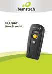
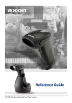
Download User`s Guide - Spirent Knowledge Base
Transcript
Spirent Chromatic 1.7 User Manual 5280 Corporate Drive, Frederick, MD. 21703 Document Version: 2.1 August 2014 Chromatic User’s Manual Contents 1 2 Introduction ..................................................................................................................................................................... 6 1.1 Overview .................................................................................................................................................................. 6 1.2 Hardware Configuration ................................................................................................................................... 6 1.3 Mobile Device Configuration ........................................................................................................................... 8 1.4 Ensure Proper Positioning ............................................................................................................................... 9 Setting User Preferences ........................................................................................................................................... 11 2.1 General.................................................................................................................................................................... 11 2.2 GPS/Time............................................................................................................................................................... 11 2.2.1 Time Synchronization............................................................................................................................. 12 2.2.2 GPS .................................................................................................................................................................. 12 2.3 Capture/Processing........................................................................................................................................... 13 2.3.1 Capture Options ........................................................................................................................................ 13 2.3.2 Content Metadata ..................................................................................................................................... 14 2.3.3 Video Processing ....................................................................................................................................... 14 2.4 Reporting ............................................................................................................................................................... 15 3 Confirming Device Positioning ............................................................................................................................... 17 4 Initiating the Test......................................................................................................................................................... 20 5 4.1 Overview ................................................................................................................................................................ 20 4.2 Testing .................................................................................................................................................................... 21 Analyzing Results ......................................................................................................................................................... 24 5.1 Reviewing for Data Integrity ......................................................................................................................... 24 5.1.1 Play ................................................................................................................................................................. 25 5.1.2 Open Session Folder ................................................................................................................................ 27 5.2 Processing the Data ........................................................................................................................................... 28 5.3 Summarizing the Results ................................................................................................................................ 30 5.3.1 Reporting Scripts ...................................................................................................................................... 31 5.3.2 Generate Excel Report From Selected.............................................................................................. 34 5.3.3 Mark Selected As Unprocessed ........................................................................................................... 37 5.3.4 Re-Run Post Processing ......................................................................................................................... 37 5.4 AV Sync KPIs” Tab .............................................................................................................................................. 38 5.5 Interpreting the Results .................................................................................................................................. 38 5.5.1 Interpreting Video Scores ..................................................................................................................... 38 5.5.2 Interpreting Audio Scores ..................................................................................................................... 39 Copyright © Spirent Communications, Inc. 2014 3 Chromatic User’s Manual 5.6 Correlating Chromatic and Third Party Data.......................................................................................... 39 5.7 Playback Delivery KPIs .................................................................................................................................... 39 6 Screen Capture (optional) ........................................................................................................................................ 41 7 Chat .................................................................................................................................................................................... 45 Appendix A Definitions of Exported Result Fields.................................................................................................. 47 Figures Figure 1-1 Chromatic unpacking...................................................................................................................................... 6 Figure 1-2 Camera.................................................................................................................................................................. 7 Figure 1-3 Hardware Mounting Fixture Side View................................................................................................... 7 Figure 1-4 Cable Connections............................................................................................................................................ 7 Figure 1-5 Chromatic System Overview ....................................................................................................................... 8 Figure 1-6 Video Test Site ................................................................................................................................................... 9 Figure 1-7 Chromatic Software......................................................................................................................................... 9 Figure 1-8 Camera Settings Starting Point................................................................................................................ 10 Figure 2-1 Accessing the Chromatic Settings Tab................................................................................................... 11 Figure 2-2 GPS/Time Settings ......................................................................................................................................... 12 Figure 2-3 Capture/Processing Settings ..................................................................................................................... 13 Figure 2-4 Capture Options Area .................................................................................................................................... 14 Figure 2-5 AVSync Thresholds Area ............................................................................................................................. 16 Figure 3-1 Chromatic Capture Tab................................................................................................................................ 17 Figure 3-2 Device Setup on the Capture Tab ............................................................................................................ 18 Figure 3-3 Time Sync Dialog ............................................................................................................................................ 19 Figure 4-1 Test Video Sample ......................................................................................................................................... 20 Figure 4-2 Chromatic Video Stream ............................................................................................................................. 20 Figure 4-3 Impaired Frame .............................................................................................................................................. 20 Figure 4-4 Video Playback ................................................................................................................................................ 21 Figure 4-5 Record Options Dialog ................................................................................................................................. 21 Figure 4-6 Content Selection Dialog ............................................................................................................................. 22 Figure 4-7 Capture Tab during Device Testing ........................................................................................................ 23 Figure 4-8 Event Type Selection .................................................................................................................................... 23 Figure 5-1 Session Description Dialog ......................................................................................................................... 24 Figure 5-2 Data>Review Tab ........................................................................................................................................... 25 Figure 5-3 Event Description Dialog ............................................................................................................................ 26 Figure 5-4 Events Dialog ................................................................................................................................................... 27 Figure 5-5 Session Folder Contents Prior to Processing ...................................................................................... 27 Figure 5-6 Session Folder Contents after Processing ............................................................................................ 28 Figure 5-7 Data >Unprocessed Screen......................................................................................................................... 28 Figure 5-8 Edit Session Processing Parameters Dialog ........................................................................................ 29 Figure 5-9 Processing the Data ....................................................................................................................................... 30 Figure 5-10 Data > Processed Screen........................................................................................................................... 31 Figure 5-11 Task Inputs / Task Outputs Dialog....................................................................................................... 32 Figure 5-12 Compare Time-Series Data Output ...................................................................................................... 32 Figure 5-13 Compare Video Score PDFs Output...................................................................................................... 33 Figure 5-14 Compare Audio Score PDFs Output ..................................................................................................... 33 Copyright © Spirent Communications, Inc. 2014 4 Chromatic User’s Manual Figure 5-15 A/V Sync Report........................................................................................................................................... 34 Figure 5-16 Video Scores by Segment ......................................................................................................................... 34 Figure 5-17 Video Score Distribution .......................................................................................................................... 35 Figure 5-18 Video Performance Comparison Chart ............................................................................................... 35 Figure 5-19 Video Score CDF ........................................................................................................................................... 36 Figure 5-20 Audio Score Statistics ................................................................................................................................ 36 Figure 5-21 Audio Score Distribution .......................................................................................................................... 36 Figure 5-22 Audio Performance Comparison Chart .............................................................................................. 37 Figure 5-23 Audio Score CDF........................................................................................................................................... 37 Figure 5-24 AV Sync KPIs .................................................................................................................................................. 38 Figure 5-25 Video Quality Score..................................................................................................................................... 39 Figure 5-26 Audio Quality Score .................................................................................................................................... 39 Figure 5-27 Playback Delivery of KPI Statistics ....................................................................................................... 40 Figure 6-1 Capture Utility ................................................................................................................................................. 41 Figure 6-2 ROXIO Profile ................................................................................................................................................... 41 Figure 6-3 ROXIO Setup ..................................................................................................................................................... 42 Figure 6-4 Image Capture Tool ....................................................................................................................................... 42 Figure 6-5 Image Capture Example .............................................................................................................................. 43 Figure 6-6 Centering the Capture Screen ................................................................................................................... 43 Figure 6-7 Import Screen Capture................................................................................................................................. 44 Figure 6-8 Selecting a File to Import ............................................................................................................................ 44 Figure 7-1 Chat Setup ......................................................................................................................................................... 45 Copyright © Spirent Communications, Inc. 2014 5 Chromatic User’s Manual 1 Introduction 1.1 Overview Spirent Communication’s Chromatic is a frame delivery testing system, for quantifying and benchmarking mobile video performance. This section provides an overview of the Chromatic workflow. Chromatic comes pre-configured and requires no software installation. The remainder of this guide is structured along the sequential processes needed to run Chromatic. Hardware Configuration Prepare the mobile device Open the Chromatic software. Specify the settings. Confirm the device positioning. Start the test. Collect and analyze your results. Each of these steps is explained in detail in the following sections. 1.2 Hardware Configuration Upon opening the Chromatic box, you should see a partially configured system as in the following image. Figure 1-1 Chromatic unpacking Remove the Wall Charger box and install the cameras, which are provided separately in the clear plastic shipping container Copyright © Spirent Communications, Inc. 2014 6 Chromatic User’s Manual . Figure 1-2 Camera Install the cameras and attach the cell phone. The finished assembly should look like the following image. Figure 1-3 Hardware Mounting Fixture Side View Remove the chromatic box and configure the cables as shown in the following image and directions. Figure 1-4 Cable Connections From the front of the device, connect the following. 1. Cell phones to channel 1 or channel 2 (Red to red and white to white). 2. Cameras to Cam 1 and/or Cam2. 3. PC to the USB port of your laptop. Copyright © Spirent Communications, Inc. 2014 7 Chromatic User’s Manual 4. Optional GPS cable to the GPS port and use the auxiliary ports (AUX) for the cell phone chargers 5. Audio capture modules and the GPS receiver to the USB hubs. 6. Plug in the power cord to power up the unit. There is no on/off switch. The USB hardware detection occurs upon the first connection. A notification displays when the automatic driver installation procedure finishes. During testing, each test device is mounted to the hardware fixture. The following diagram shows the Chromatic system configuration UE11 UE12 UE21 UE22 Front Camer a UE1 2 UE11 UE22 Chromatic Laptop MEASURING TWO SIMULTANEOUS ONE WAY VIDEO CHAT SESSIONS Headset Audio Out Using Chromatic Audio Cable Optional VGA UE 21 Headset Audio In Daptor 2 Optional GPS Audio Out with Splitter Hub – PC USB Connect Chromatic Audio Cable to Daptor 2 Line Input Play-out Laptop (Can also use same Chromatic Laptop with extended monitor) Connect Playout Laptop Audio Out to Daptor 2 Line In via Chromatic Cable (Red Connector) Connect Daptor 2 Headset Output to UE Headset using 3.5mm Daptor 2 cable for HTC, others. For Samsung, need R2 – S reversal adapter, or 2.5mm Daptor 2 cable with R2-S reversal adapter Camera Capture - USB Figure 1-5 Chromatic System Overview 1.3 Mobile Device Configuration Perform the following steps to configure the test devices for Chromatic testing. 1. Turn on each test device. 2. In the device’s web browser, navigate to the standard Spirent or custom test site containing a series of test videos: Copyright © Spirent Communications, Inc. 2014 8 Chromatic User’s Manual Standard Spirent test site: http://updates.metricowireless.com/cw/index.html Custom test site. Navigate to the custom test clip URL listed at the bottom of the Capture tab in the Chromatic software. 3. The videos on the test site use different video codes and frame rates. The videos marked FL are in Flash format and can be played in a web browser. The others use standard Real Time Streaming Protocol (RTSP) for use in a video player. Figure 1-6 Video Test Site 4. Click any item in the Content column to select the test video. 5. Adjust the handset volume level to approximately 75% of the maximum. 6. Connect an audio cable from each audio capture module to the headset jack of each mobile device. 7. Position the test devices in the rig. 1.4 Ensure Proper Positioning Use the Chromatic software to ensure the test devices are properly positioned in front of the cameras. This section discusses the basics of positioning and configuring the camera. Fine tuning is discussed in the next chapter. Figure 1-7 Chromatic Software From this screen perform the following steps: Copyright © Spirent Communications, Inc. 2014 9 Chromatic User’s Manual 1. To begin video performance testing, double-click the Chromatic icon on the Windows Desktop, or from the Windows Start Menu select All Programs> Chromatic. The first time Chromatic is opened, an internet connection is required for product activation. 2. . Click Camera Settings and the following screen displays. Figure 1-8 Camera Settings Starting Point Spirent offers the following recommendations for optimal camera settings. If possible, adjust your camera settings while playing a test video directly stored on the device (for example, on the SD card) The camera should be positioned under the same light shade you will be using for your test. If possible, set the phone screen brightness to a fixed value, around 75% of the maximum. Use the settings below as a default, then make small adjustments to the gain to produce the desired level of picture contrast: ○ Disable automatic gain control ○ Disable automatic exposure control ○ Set exposure to 1/120 s ○ Set gain to 645 – adjust as necessary Copyright © Spirent Communications, Inc. 2014 10 Chromatic User’s Manual 2 Setting User Preferences Prior to first use, Chromatic must be configured with user preferences. To configure the program, specify General Settings, GPS/Time Settings, and Capture/Processing Settings. Each of these configuration options is accessible from the Chromatic Settings tab. The default settings are suitable for most users. Figure 2-1 Accessing the Chromatic Settings Tab 2.1 General To specify general settings for Chromatic, choose whether to Check for Updates on Startup to determine whether a newer version of Chromatic is available (recommended). The Enable Remote Control via TCP socket 7073 option is only visible to customers who have purchased this optional command set for controlling Spirent’s Nomad remotely via any socket client. This option should be selected in order to access Remote Control functionality. Remote functionality includes Time synchronization, which consists of: Configuration of capture channels Starting/stopping a capture session Performing post-processing on a session For full details see the Spirent Chromatic Remote Control Guide. 2.2 GPS/Time Use this option to specify settings related to time synchronization and GPS on the GPS/Time tab. Copyright © Spirent Communications, Inc. 2014 11 Chromatic User’s Manual Figure 2-2 GPS/Time Settings 2.2.1 Time Synchronization Time synchronization is required when the data captured with Chromatic will be correlated with Qualcomm eXtensible Diagnostic Monitor (QXDM) data collected on another device. Time synchronization should also be performed on the QxDM collection device (if necessary, through the operating system) for proper correlation. To specify time synchronization options in Chromatic perform the following steps. 1. Internet Time Server – Chromatic will synchronize the PC’s clock to internet time on demand. In order to use this method you must have a dedicated internet connection. 2. GPS - Spirent recommends using GPS for mobile environments. ITS may encounter latency issues in a drive test. GPS – Chromatic will synchronize the PC’s clock to GPS time on demand. Spirent recommends using this time synchronization method for mobile tests. 3. Sync time -on application startup to automatically perform time synchronization when the Chromatic software is opened. Do not select this option if the locally captured Chromatic data is to be correlated with QXDM data collected on another device. 2.2.2 GPS Chromatic can record GPS information during testing. Location information can be used to display data testing results graphically in MapInfoTM and similar mapping applications. To capture GPS information with Chromatic, perform the following steps. 1. Connect a GPS device and enable the device to acquire a signal. 2. In the GPS area of the Settings dialog, confirm that the Enable GPS box is selected. Copyright © Spirent Communications, Inc. 2014 12 Chromatic User’s Manual 3. Select the GPS Type as Garmin or NMEA (for DeLorme or any device that supports this standard). For a Garmin device, click the Detect Garmin GPS button to activate. For an NMEA device, select the corresponding COM Port. If available, live GPS data will display here. This includes: Current latitude and longitude GPS Fix status, which is indicated by the colored circle in this area. Hover over the circle for the status tooltip. The status is provided as NO FIX, 2-D DIFF, 3-D or 3-D DIFF. DIFF status refers to a lock on differential GPS sensors, providing a more accurate location reading than standard GPS. The blinking heart The yellow triangle indicates an error. Click the Restart GPS button to activate (in some cases it may be necessary to click this button twice). blinks each time a GPS message is received. 2.3 Capture/Processing Specify settings related to video capture and processing on the Capture/Processing tab. The different areas of this tab are discussed in detail below. Figure 2-3 Capture/Processing Settings 2.3.1 Capture Options Use these fields to control the recording session. Copyright © Spirent Communications, Inc. 2014 13 Chromatic User’s Manual Figure 2-4 Capture Options Area Healthy FPS Threshold – The limit of frames per second. This is primarily internal testing data and not intended for customer use. FPS Alarm Threshold - This is primarily internal testing data and not intended for customer use. Default duration to unlimited – Select this option to end the test session manually by clicking Stop. Default duration (in seconds) – When Default duration to unlimited is left unchecked, this field provides the test duration. Automatically switch to Review tab when recording completes – At the end of the test session, Chromatic automatically display this screen to replay the recorded video or review the raw data in the session folder. Prompt for device metadata – Select this option to display fields in the Record and Config dialogs for entering device Make, Model, Role and HW Identifier information. If entered, this information will appear in the Chromatic output report. 2.3.2 Content Metadata Enter the URL and the Path of the test videos in use. The URL and Path must match the destination entered on the mobile device. The default settings point to the standard Spirent-hosted video test clips and are appropriate in most cases. The files contained in the directory specified here are listed upon test initiation, allowing the user to specify the actual file in use for the test. 2.3.3 Video Processing Use these fields to control the processing of session data. 2.3.3.1 Enable concurrent processing Check this box to allow Chromatic to process multiple output files at the same time for data analysis. This option may shorten overall processing time on powerful, multi-core systems. In some cases, concurrent processing may result in a drastic decline in processing speed. If this occurs, Spirent recommends disabling this option or lowering the Max number of concurrent processes allowed. Copyright © Spirent Communications, Inc. 2014 14 Chromatic User’s Manual 2.3.3.2 Max number of concurrent processes Use this option to specify the maximum number of simultaneous processes allowed when concurrent processing is enabled. Raise this value to take advantage of powerful processing capabilities of multi-core systems and lower overall processing time. The maximum value allowed in this field corresponds to the machine’s number of processors. Lower this value if performance suffers with concurrent processing on less powerful machines. The standard Spirent-provided Chromatic laptop contains a processor with eight cores, allowing up to eight captures to be processed simultaneously. Set the Max number of concurrent processes to eight to take advantage of the laptop’s computing capabilities. This option maximizes efficiency by shortening overall processing time in batch mode. 2.3.3.3 Notify when processing completes Select this option if you wish Chromatic to issue a pop up message when the test completes. 2.3.3.4 Freeze/Impairment timer trigger (FITT) Use this option to set the number of individually impaired images the system will ignore before registering the test as impaired. For example, the system comes configured to 10 (an allowed range of 1 to 10 with the default as 10), then it would require 10 or more impaired images to qualify for impaired status. Spirent recommends you set this parameter to 6. Assuming the image is transmitting at 10 frames per second, a setting of six would be 200 Ms. To create a 200 ms threshold (corresponding to human eye sensitivity) you would use the following formula. FITT = .2 * framerate of the test video. If the testframe = 30 FPS then the FITT = 6. The FITT impacts the calculation of frozen and impaired frames as a low FITT (1) makes Chromatic very sensitive where as a FITT of 10 would be more forgiving. If you change the FIT you do not need to recreate the capture. You only need to re-run post processing as shown in section…. 2.4 Reporting Use these fields to define the BadAVSync% parameter on the Validation tab of the Chromatic output report. In the ideal case, the test video and corresponding audio are captured simultaneously by the Chromatic software. While a small amount of offset (with audio either leading or lagging the video) is acceptable, a large offset between the audio and video is often undesirable. The BadAVSync% parameter captures the frequency of undesirable offset conditions. Copyright © Spirent Communications, Inc. 2014 15 Chromatic User’s Manual Figure 2-5 AVSync Thresholds Area Set AVSync Thresholds (milliseconds) – Offset within the green center area of the thresholds bar is considered acceptable. Set the maximum acceptable audio lag using the left-hand threshold setting. Set the maximum acceptable audio lead using the right-hand threshold setting. AVSync Calibration Factor – The offset value off which the AVSync Thresholds are based. With the Calibration Factor set at 0 and the AVSync Thresholds at -200 ms and 50 ms, offsets between -200 ms and 50 ms are considered acceptable. With the Calibration Factor set at 50 and the AVSync Thresholds at -200 ms and 50 ms, offsets between -150 ms and 100 ms are considered acceptable. Note: In most cases, the default settings in this area should be maintained. If adjustment is necessary, please contact Spirent Support for more information. Copyright © Spirent Communications, Inc. 2014 16 Chromatic User’s Manual 3 Confirming Device Positioning Prior to testing, the position of each test device must be confirmed using the Config option on the Capture tab. Figure 3-1 Chromatic Capture Tab To confirm that the test devices are positioned correctly perform the following steps. 1. Check the Enabled box for each device to be used during testing. 2. Select the Video Device that will be capturing video for the channel. 3. Select the Audio Device that will be capturing audio for the channel. Note that capturing audio is optional and is not required to perform tests. 4. If the metadata fields (Make, Model, Role, HW Identifier) appear, populate as desired. This information will appear in the Chromatic output report. To control whether these fields appear, use the Prompt for device metadata setting on the Settings> Capture/Processing tab. 5. Click OK to accept the settings or click Cancel to exit without saving. At this time, the test videos will appear in the Video A and/or Video B windows. The audio and video sampling statistics that appear in the Information area are used to ensure that the test devices are positioned properly. Copyright © Spirent Communications, Inc. 2014 17 Chromatic User’s Manual Figure 3-2 Device Setup on the Capture Tab 1. Confirm that the test video is actively playing on the test device. 2. For the best test results, the Circle Detection Rate and the Frame Detection Rate should be as high as possible. These values are color-coded green, yellow and red to indicate good, fair and poor performance with respect to detection rate. 3. Physically adjust the cameras or use the Camera Settings button to maximize the Circle Detection Rate and the Frame Detection Rate. See Appendix A for recommendations on finding the optimal camera settings. For the best results: Circle Detection Rate should be equal to 100%. Frame Detection Rate should fall between 50% and 100%. 4. Press Reset following any camera changes to confirm the metrics. 5. Inspect the audio performance bar to the right of the video playback area to confirm that audio is playing at an acceptable level. The audio bar background color indicates the volume level: Green background indicates that the audio is at an acceptable level. Yellow background indicates that the audio level is too low or missing. Red background indicates that the audio level is too high. 6. If the volume is too high or too low, confirm that the device volume is set to approximately 75% of the maximum level. The audio level can then be adjusted by rotating the SENS control knob on the audio capture module. 7. You can also check the detected audio level by the device from the Windows Sound menu: Copyright © Spirent Communications, Inc. 2014 18 Chromatic User’s Manual 8. 9. 10. 11. 12. 13. Right-click on the Volume icon in the Windows System Tray. Select Recording Devices. Check the meter to the right of each Chromatic audio capture unit to determine the level of audio detected by the device. Confirm that the GPS is reporting location if enabled. If Sync time on application startup is not selected, manually synchronize the time if time sync is required for correlation with data collected from another source such as QXDM On the Chromatic Capture tab, select the Time Sync button. Select the Source as Internet Time Server or GPS. Select the Sync Now button. Once the status shows as Time sync completed successfully, click OK to dismiss the Time Sync dialog. Figure 3-3 Time Sync Dialog Copyright © Spirent Communications, Inc. 2014 19 Chromatic User’s Manual 4 Initiating the Test 4.1 Overview The system streams a test video from the hosted video server to the test device. The Spirentsupplied test video shows both a live action sequence and a series of circular symbols that are frame markers. The symbol position changes as the video plays and identifies the video frame number, as shown in the following image. Figure 4-1 Test Video Sample Chromatic marks individual frames with symbols, which it automatically interprets as frame numbers during playback on the test device. Chromatic automatically detects these symbols when observing video played back on the test device, as shown in the following image. Figure 4-2 Chromatic Video Stream The video camera and control software record the captured video from the handset. Chromatic processes this video and assesses each frame based upon timing and video integrity using a Gross Error Detection algorithm. Chromatic uses a five-point video quality score to summarize performance. Chromatic also assesses streaming media audio performance. The audio portion of the Chromatic test clip plays a repeating sequence of dual-tone multi-frequency signaling (DTMF). The system records and scores the audio and based upon the number of tones correctly received. The processing software also keeps timing information about which video frames correspond to the audio tones. Chromatic also reports impaired and frozen frames. In a frozen frame the circular frame symbols are distinguishable, but, no change can be detected from the previous frame. As shown in the following image. Figure 4-3 Impaired Frame Copyright © Spirent Communications, Inc. 2014 20 Chromatic User’s Manual The following figure displays Chromatic frame detection. Figure 4-4 Video Playback Combined, the video score, audio score, impairment and freeze metrics provide a quantitative assessment of mobile video performance. 4.2 Testing When the video, audio, and GPS devices are working, start testing by perfuming the following steps. 1. Click Record to begin testing. Figure 4-5 Record Options Dialog Copyright © Spirent Communications, Inc. 2014 21 Chromatic User’s Manual 2. Either enter the Max Record Time in Hours, Minutes, and Seconds; or, check Unlimited to continue recording until stopped by the user. The setting in the Max Record Time area defaults to the Default Duration specified on the Settings tab. 3. Enter an identifying Description (such as handset type) to be used as the file name for each capture in this session. Note: Spirent recommends entering the device name and video content clip name in this field. For example: “Device XYZ, CW-064-FL”. 4. If the metadata fields (Make, Model, Role, HW Identifier) appear, populate as desired. This information will appear in the Chromatic output report. To control whether or not these fields appear, use the Prompt for device metadata setting on the Settings>Capture Processing tab. 5. In the Video Content area, use the drop-down or the Chooser to match the video playing on the test mobile. Click OK to confirm the selection. If you changed the test videos in use through the Content Metadata area of the Settings>Capture/Processing tab, click Refresh in the Content Selection dialog to display the correct file list. Figure 4-6 Content Selection Dialog Click Start in the Record Options dialog to start the test. During testing, each test video will appear in the Video A or Video B area of the Capture tab, and the Duration and Information areas will update continuously as shown in the following example. Copyright © Spirent Communications, Inc. 2014 22 Chromatic User’s Manual Figure 4-7 Capture Tab during Device Testing The video that appears is a sample of the live video being captured. As a result, not every video frame is displayed. An audio warning (an electronic pulse) sounds if the camera is not properly positioned and cannot detect the frame or circles for more than one second. Check the Mute Audio Warnings box to disable these notifications. Use the Insert Event Marker button to log a playback interruption. Figure 4-8 Event Type Selection Select whether this is an instance of Device Interrupted Playback or User Interrupted Playback. The Event Type and Time will appear in the Events dialog accessible from the Data > Review page. Events are also presented in the Chromatic output report. Copyright © Spirent Communications, Inc. 2014 23 Chromatic User’s Manual 5 Analyzing Results Click Stop to end the test and enter an optional description. The system adds the test file to the list of files to be processed. Check Discard session to delete all files associated with this capture. Figure 5-1 Session Description Dialog The steps to analyze video quality data captured with Chromatic include: Reviewing the recorded video and captured session files for data integrity Processing the data into a meaningful format for analysis Summarizing the results Interpreting the results These steps are described in the following sections. Additionally, Chromatic data may be correlated with RF data from QXDM or IP data from a network sniffer. 5.1 Reviewing for Data Integrity When data collection is complete, navigate to the Data Review tab. The Data Review tab may appear if the Automatically switch to Review tab when recording completes option has been selected on the Settings tab. Copyright © Spirent Communications, Inc. 2014 24 Chromatic User’s Manual Figure 5-2 Data>Review Tab This tab allows the verification of data integrity prior to processing the results into a formatted output. The review mechanisms available here are: Playing the recorded video Opening the Session Folder These review techniques are described in the following sections. 5.1.1 Play To gauge user perception of video quality and to ensure that captured results align with expectations, the video captured during each Chromatic test may be played back on the Data>Review screen. You can also use this screen to: Set the session start and end times Exclude portions of data from report calculations Flag significant events Measure the time between playback initiation and the first frame seen To play the video: 1. Select the desired test file from the Session drop-down. 2. Click Play in the video playback area. Setting the Session Start and Session End limits the reporting for the session to data collected between these time markers. To set the Session Start and Session End: 1. Position the playback cursor at the desired session start time. 2. Select Add Event >Set Session Start and End> Session Start. 3. Position the playback cursor at the desired session end time and repeat, choosing Session End this time. Copyright © Spirent Communications, Inc. 2014 25 Chromatic User’s Manual 4. The Session Start and Session End times will appear in the Events dialog. Data occurring before the Session Start marker and after the Session End marker will be ignored in the Chromatic output report. The Exclude Video Range/Segment choice provides the option to mark data for exclusion from the final report. To exclude a range: 1. Select Add Event>Exclude Video Range/Segment > Range. 2. In the Define Range dialog, slide the red markers along the playback bar to define the range to exclude. 3. In the Description box, enter descriptive text giving the reason for the exclusion. 4. Click OK to continue. 5. The excluded range will appear in the Events dialog. Data within this range will be ignored in the Chromatic output report. Note: The actual time range excluded will start at the beginning of the 12-second segment containing the start marker and finish at the end of the 12-second segment containing the “end” marker. For example, if the user selects to exclude 10 seconds to 20 seconds, the actual excluded time range will be from 0 seconds to 24 seconds. Chromatic operates exclusively in 12-second segments. To exclude a segment: 1. Position the playback cursor at the time to exclude. 2. Select Add Event >Exclude Video Range/Segment>Segment. 3. Enter an Event Description. 4. The 12-second range containing the selected point will appear in the Events dialog. Data within this range will be ignored in the Chromatic output report. Figure 5-3 Event Description Dialog To manually mark an event in the recorded video: 1. Position the playback cursor at the desired event time. 2. Select Add Event >Add Event and then one of the three options: User Interrupted Playback Device Interrupted Playback Custom – When this option is selected, it is necessary to enter an Event Description. The marked event will appear in the Events dialog and in the Chromatic output report. Copyright © Spirent Communications, Inc. 2014 26 Chromatic User’s Manual To measure the time between playback initiation and first frame seen: 1. Position the playback cursor at the time of playback initiation. This is usually the time when the user’s finger can be seen manually pressing the button to start the video. 2. Select Add Event> First Frame Time Measurement> Playback Initiated. 3. Wait until you see the video start to play. 4. Select Add Event> First Frame Time Measurement>First Frame Seen. 5. The Playback Initiated and First Frame Seen events will appear in the Events dialog and in the Chromatic output report. The time difference between the First Frame Seen and the Playback Initiated is reported as the Startup Time on the Validation tab of the Chromatic output report. 6. Select the Events button on the Data > Review tab to view all events entered during and after testing. Figure 5-4 Events Dialog 5.1.2 Open Session Folder The Session Folder for each recorded test includes the recorded *.WMV file and associated GPS and capture logs. After processing (see Section 9.2), this folder will also contain video and audio scores in text and comma delimited format, as well as a time-series plot depicting key test metrics. Access to this raw data may be desirable for detailed analysis or data manipulation. To access the Session Folder: 1. On the Data>Review tab, select the desired test file from the Session drop-down. 2. Click the Open Session Folder button. Figure 5-5 Session Folder Contents Prior to Processing Copyright © Spirent Communications, Inc. 2014 27 Chromatic User’s Manual 3. After processing the screen will look like the following. Figure 5-6 Session Folder Contents after Processing 5.2 Processing the Data To process the data perform into a useable format perform the following steps. 1. Navigate to the Data>Unprocessed screen. Figure 5-7 Data >Unprocessed Screen 2. The processing queue lists Unprocessed test files. Use the Add button to add locally stored files to the queue for processing. Use the Remove Selected button to remove files from the Copyright © Spirent Communications, Inc. 2014 28 Chromatic User’s Manual queue. Files removed from the queue will not be deleted and can be processed at a later time. 3. Use the Edit Selected button to modify the processing parameters for a file. In most cases, the default parameters should be maintained. Please accept the defaults and do not change them unless instructed by Spirent Support. Figure 5-8 Edit Session Processing Parameters Dialog The Circle Radius Min and the Circle Radius Max settings are detected from the information stored within the capture file. If post-processing is not working, these settings may need to be manually adjusted. Please contact Spirent Product Support for more information. The Averaging Window (Video and Audio) settings refer to the number of frames used as the unit of measurement for determining how many expected frames were actually captured. For example, if the test video frame rate is 15 frames/second and the Video Averaging Window is 5 seconds, you would expect to receive 75 frames during that time. If fewer than 75 frames are received, the video will be considered impaired or frozen for that measurement. The FrameProcessor Additional Command Line Text field is generally reserved for Spirent use. Please contact Spirent Product Support for assistance with this field. 4. Click OK to accept the settings and exit the Edit Session Processing Parameters dialog. 5. Select one or more unprocessed files from the list on the Data> Unprocessed screen. The selections made in the Video Processing area of the Settings tab affect the processing sequence: Checking Enable Concurrent Processing on the Settings tab allows Chromatic to process multiple files at the same time. This option may shorten overall processing time on powerful, multi-core systems. If performance suffers with the Concurrent Processing option, lower the Max number of concurrent processes setting, or disable concurrent processing entirely. 6. Click the Process Selected button underneath the file list. Copyright © Spirent Communications, Inc. 2014 29 Chromatic User’s Manual Figure 5-9 Processing the Data 7. Each file that has been successfully processed will move from the Data> Unprocessed screen to the Data> Processed screen. 8. The Processing Complete dialog will appear after all files have been processed. Note that the processing for each file will take at least as long as the capture and may take up to twice as long. 9. Click OK to exit. 5.3 Summarizing the Results Navigate to the Data> Processed screen to summarize the results. Copyright © Spirent Communications, Inc. 2014 30 Chromatic User’s Manual Figure 5-10 Data > Processed Screen 5.3.1 Reporting Scripts The Reporting Scripts button on the Data >Processed page provides access to informational charts for any file that has been processed. Analysis options here include: Compare Time-Series Data Compare Video Score PDFs Compare Audio Score PDFs A/V Sync Report To display the analytical charts perform the following steps. 1 Select the desired test file(s). 2 Click Reporting Scripts and choose the desired action. 3 Confirm that each file to be compared has been added in the Compare Time-Series Data dialog. Copyright © Spirent Communications, Inc. 2014 31 Chromatic User’s Manual Figure 5-11 Task Inputs / Task Outputs Dialog 4 The time-series data, video score PDFs or audio score PDFs will appear together for comparison. Figure 5-12 Compare Time-Series Data Output Copyright © Spirent Communications, Inc. 2014 32 Chromatic User’s Manual Figure 5-13 Compare Video Score PDFs Output Figure 5-14 Compare Audio Score PDFs Output 5 The A/V Sync Report provides both time-series and distribution views for audio variation. Audio variation refers to the time offset between the captured video and audio. When the audio leads the video, audio variation is reported as a positive number. When the audio lags the video, audio variation is reported as a negative number. Copyright © Spirent Communications, Inc. 2014 33 Chromatic User’s Manual Figure 5-15 A/V Sync Report 5.3.2 Generate Excel Report From Selected The Data> Processed page also provides the option to generate an Excel report containing overall, session-level and segment-level statistics for the data. To generate the Excel report perform the following steps. 1. Select the desired test file(s). 2. Use the up and down arrows to order the sessions as you wish for them to appear in the report. 3. Select the Generate Excel Report from Selected button. 4. Enter a file name and save. The video performance table and charts shown below are included on the formatted REPORT tab of the Excel output report. Similar analysis views are provided for audio performance. Additional report tabs provide statistics for the data aggregated by channel, session and video segment. . Figure 5-16 Video Scores by Segment Copyright © Spirent Communications, Inc. 2014 34 Chromatic User’s Manual Figure 5-17 Video Score Distribution Figure 5-18 Video Performance Comparison Chart Copyright © Spirent Communications, Inc. 2014 35 Chromatic User’s Manual Figure 5-19 Video Score CDF Figure 5-20 Audio Score Statistics Figure 5-21 Audio Score Distribution Copyright © Spirent Communications, Inc. 2014 36 Chromatic User’s Manual Figure 5-22 Audio Performance Comparison Chart Figure 5-23 Audio Score CDF 5.3.3 Mark Selected As Unprocessed Use this option to change the status of a processed file to that of unprocessed. You have the reverse option under the Processed tab. 5.3.4 Re-Run Post Processing Should you wish to change or correct the FITT, as discussed in section 2.4, you can use this option to re-run an already finished capture at a different FITT. Copyright © Spirent Communications, Inc. 2014 37 Chromatic User’s Manual 5.4 AV Sync KPIs” Tab The AV Sync KPIs tab provides a comprehensive list of summary performance data and Key Performance Indicators (KPIs) relating to the audio/video sync performance of the capture session(s). AV Sync KPIs AV Sync - Lead Limit, ms AV Sync - Lag Limit, ms Average of AV Sync Lead, ms Capture 1 Capture 2 Capture 3 50 50 50 Capture 4 50 -200 -200 -200 -200 97 94 87 None Average of AV Sync Lag, ms -159 -99 -162 -110 Max AV Sync Lead, ms Max AV Sync Lag, ms 110 111 107 0 -400 -100 -403 -110 Segment Count (12s each) 11 10 10 10 No of Segments > +50ms No of Segments <-200ms 3 2 2 0 2 0 2 0 No of Segments within Limits 6 8 6 10 54.5% 80.0% 60.0% 100.0% % Segments Within Limits AV Sync – Lead Limit, ms Average of AV Sync Lead, ms The audio lead threshold. The default value is 50ms, but it can be changed according to the operator’s requirement. The audio lag threshold. The default value is -200ms, but it can be changed according to the operator’s requirement. The average of the audio lead for all leading segments. Average of AV Sync Lag, ms The average of the audio lag for all lagging segments. Max AV Sync Lead, ms The maximum segment value of the audio lead for all leading segments. Max AV Sync Lag, ms The maximum (absolute) segment value of the audio lag for all lagging segments. Segment Count (12s each) The number of 12-second video segments included in this session. No of Segments > +50ms The number of segments which had leading AV audio higher than the lead threshold. No of Segments < -200ms The number of segments which had lagging audio less than the lag threshold. No of Segments within Limits The number of segments in which the audio lead or lag was within the threshold limits. % Segments within Limits The % of segments in which the audio lead or lag was within the threshold limits. AV Sync – Lead Limit, ms Figure 5-24 AV Sync KPIs 5.5 Interpreting the Results Chromatic calculates video and audio scores based on the difference between the observed and expected results during testing. This section describes how Chromatic calculates the video and audio scores, and how these scores correlate to user-perceived quality. 5.5.1 Interpreting Video Scores Chromatic calculates the video score by comparing the number of observed and expected video frames. Expected frames are calculated as the number of unique video frames that should appear in each 12-second segment based on the frame rate of the source video. Observed frames are calculated based on the circular markers captured in each frame of the recorded video. An impaired frame is distorted and users can no longer detect the circular marker symbols. A frozen frame is one in which the circular frame symbols are distinguishable, but no change has been detected from the previous frame. Copyright © Spirent Communications, Inc. 2014 38 Chromatic User’s Manual The video score is the ratio of observed video frames to expected video frames, represented on a 5point scale: Score Video Quality 5 Excellent 4 Good 3 Fair 2 Poor 1 Bad Figure 5-25 Video Quality Score 5.5.2 Interpreting Audio Scores Chromatic calculates the audio score by comparing the number of observed and expected audio tones in each 12-second segment. The audio track contains a sequence of DTMF tones. The Chromatic software assesses whether the expected tones are recognized. The audio score is the ratio of observed audio tones to expected audio tones, represented on a 5point scale. Score Audio Quality 5 Excellent 4 Good 3 Fair 2 Poor 1 Bad Figure 5-26 Audio Quality Score In addition, the DTMF audio tones are synchronized to specific video frames. Chromatic evaluates the timing of the tones with respect to the video frames. The result is presented as an audio advance or delay with respect to the video in the A/V Sync Report. Typically, the smaller the advance or delay, the higher the quality of the end user experience. 5.6 Correlating Chromatic and Third Party Data Reserved for future use 5.7 Playback Delivery KPIs The Playback Delivery of KPIs tab provides comprehensive data to evaluate the performance of streaming videos on networks. Carriers will use this to determine the quality behavior of their transmissions. The Excel spread sheet from this tab will indicate the start and stop time of videos as well as accurate assessments of the access/buffer phase and playout phase. Copyright © Spirent Communications, Inc. 2014 39 Chromatic User’s Manual Description The nomenclature used to label or identify this test as entered in the setup. Channel Finish Frame Reached The description of the capture channel as entered in the Record Options dialog at the start of the test Chromatic automatically tags a capture as successful or not successful depending upon a threshold timeout ratio of N seconds I Chromatic recording ends when end frames are encountered. Measured Duration Measures duration is from the first moving frame, to the timestamp of the first occurrence Latency to First Moving Frame Measures the startup latency from "Play" to "First Moving Frame." Total Impaired Duration When the Video is lost (no circles detected) vs when the video is tiled (at least one circle detected, but no frame is detected The number of times and durations that the playback was interrupted. Playback Success Impaired Period Count Rebuffering Test Video Length Re-buffering time will be measured as the Total Playback time minus the source clips known duration. Playback percentage is a function of Total playback time and re-buffering time. It should be measured as: ([TotalPlaybackTime]-[RebufferingTime]/[TotalPlaybackTime]) Actual length of the video with a known length with a special indicator that marks its end Timeout Threshold Pre-set seconds of the timeout threshold. Playback Percentage Figure 5-27 Playback Delivery of KPI Statistics Copyright © Spirent Communications, Inc. 2014 40 Chromatic User’s Manual 6 Screen Capture (optional) If you purchase the screen capture option, you will be able to remotely capture images on your cellphone, import them into chromatic, and analyze the results. Screen capture is a separate program that requires you purchase a license. The maximum length of a video you can capture is 90 minutes at 60 fps. The audio will be between192 and 196 kbps. To run this upgrade, perform the following steps: 1. Contact Spirent Technical Support to obtain a screen capture download. 2. After receiving the file, use any unzip tool to perform an extract all. After the extracts are complete, Spirent recommends you create a shortcut icon on your desktop. Also, set your desktop view to 100%. 3. Click on the desktop executable and a screen like the following displays. Figure 6-1 Capture Utility 4. From the Capture Utility menu select an aspect ratio to record the video. 5. Set the Output Location as the folder in which you wish to store the data you captured in the images. These files will be imported into Chromatic. 6. Enable the GPS option if desired (and connect your GPS device). 7. By unclicking the show capture option you can remove the red capture box until you need it. 8. Connect the ROXIO GAMECAP HD PRO (provided by Spirent) to the laptop and the cellphone. As shown in the following image. Figure 6-2 ROXIO Profile Copyright © Spirent Communications, Inc. 2014 41 Chromatic User’s Manual 9. Connect the cellphone to the ROXIO unit and connect the unit to the USB port on your laptop as in the following image. Figure 6-3 ROXIO Setup 10. Open the ROXIO software and a screen like the following displays. Figure 6-4 Image Capture Tool 11. Attach your cell phone and begin playing your video. You may use the recommended Spirent approved test videos found at http://www.youtube.com/user/seshsimha. 12. When the image is playing, click Capture on the ROXIO screen and the image on the telephone should appear as in the following screen. If you do not see the screen, verify that the Input is set to HDMI. If you still do not see the screen, try restarting your cellphone. Copyright © Spirent Communications, Inc. 2014 42 Chromatic User’s Manual Figure 6-5 Image Capture Example 13. Center the two red boxes over the image with the smaller, interior, darker box centered over the spinning circles as in the following image. Figure 6-6 Centering the Capture Screen 14. Begin recording your chosen video by clicking Start on the Chromatic software. 15. Click Start on the Capture Utility and the system automatically replaces the red capture field with flashing green brackets. 16. Click Stop to end the session. 17. After stopping and storing the file, return to the main Chromatic program and import the file through the Import Screen Capture File under the Add dropdown menu of the Data>Unprocessed tabs. As shown in the following figure. You will not see this option unless you have obtained the license for Chromatic Screen Capture. Copyright © Spirent Communications, Inc. 2014 43 Chromatic User’s Manual Figure 6-7 Import Screen Capture 18. Click Import Screen Capture File, select the file you saved and it appears in the list as shown in the following screen. Figure 6-8 Selecting a File to Import 19. Select the file or multiple files and click Process Selected. 20. You can now perform the same data analysis that you would on a standard Chromatic file. Copyright © Spirent Communications, Inc. 2014 44 Chromatic User’s Manual 7 Chat Use the Chat function to test the video quality of your transmissions. You can configure, as shown in the previous diagrams, Chromatic to simultaneously capture two video from different cameras. You can use this to measure video chat latency between source stimulus and UERx, or between UETx, and UERx. Chromatic treats this as any other data input. To install and enable the Chat function, perform the following steps. 1. Open your laptop as seen in the following figure. Figure 7-1 Chat Setup 2. Set up devices for Skype. 3. Set up Daptor 2. 4. Play Stimulus video BBBBIG20A-30min.mp4 on the laptop or play the 3rd UE (Stimulus UE) download from https://www.dropbox.com/s/97zl1elcrpwa93d/BBBBIG20A-30min.mp4 or set up chat between the Tx and Rx UEs. 5. Align the camera and achieve a minimum of a 40% frame detection. 6. Verify the audio is transmitting from Tx to Rx. Keep recording levels medium to keep the tones from becoming distorted. 7. Record for 3-10 minutes at a frame detection rate of 40 percent for Chat. 8. Click Stop. 9. Process the KPIs Copyright © Spirent Communications, Inc. 2014 45 Chromatic User’s Manual 10. Note that Chromatic Score and Weighted Session Scores are referenced to 20fps for Chat when you use 20fps stimulus. 11. Review your Excel output, which should look like the following example. This report contains a specific comparison file (indicated in yellow).By comparing the time offsets for the same Marker Number in Captures A and B, the report displays the end-to-end latency. In this example, the LKPI = 233 ms Copyright © Spirent Communications, Inc. 2014 46 Chromatic User’s Manual Appendix A Definitions of Exported Result Fields The Data > Processed page in Chromatic provides the Generate Excel Report from Selected option as a way to obtain detailed setup and performance results. This Appendix describes many parameters that can be found in the exported result file. REPORT Tab This formatted tab summarizes video and audio performance for the selected sessions. Portions of the data marked by the user for exclusion are omitted from the calculations on the REPORT tab. Video Score Statistics Session Score (Average) The mean video score for this session. Standard Deviation The spread of the video score data for the session about the mean. Maximum Score The maximum video score for this session. Segment Count The number of 12-second video segments included in this session. Duration (seconds) The length of the session in seconds. % of time Frozen The amount of time the video was frozen divided by the total session duration. Frozen video occurs when the circular frame markers are distinguishable but no change was detected from the previous frame. The amount of time the video was impaired divided by the total session duration. Impaired video occurs when the video is so distorted it is not possible to distinguish the circular frame markers. The percentage of video score measurements for the session with a value greater than or equal to 3.0. The percentage of video score measurements for the session with a value less than 2.0. The percentage of video score measurements for the session with a value greater than or equal to 4.0. The number of events marked by the user either during testing or during data reviews. This statistic includes playback interruptions by both the device and the user. % of time Impaired % greater than or equal to 3.0 % less than 2.0 % greater than or equal to 4.0 Device Playback Interrupted Audio Score Statistics Average The mean audio score for this session. Standard Deviation The spread of the audio score data for the session about the mean. Maximum Score The maximum audio score for this session. Segment Count The number of 12-second video segments included in this session. Duration (seconds) The length of the session in seconds. % greater than or equal to 3.0 The percentage of audio score measurements for the session with a value greater than or equal to 3.0. % less than 2.0 The percentage of audio score measurements for the session with a value Copyright © Spirent Communications, Inc. 2014 47 Chromatic User’s Manual less than 2.0. % greater than or equal to 4.0 The percentage of audio score measurements for the session with a value greater than or equal to 4.0. Validation Tab This tab contains statistics to quickly help determine whether valid data was captured during each test session. Session A unique identifier for each test session included in the data set. Channel The Chromatic video capture channel. Channel Description Source Frame rate Observed FPS Mean The description of the capture channel as entered in the Record Options dialog at the start of the test. The frame rate of the captured video content. Detected Markers Camera Capture FPS Setting Camera Capture FPS Mean Camera Capture FPS Min Included Seg Count Excluded Seg Count Event Count Interrupt Count Startup Time (seconds) Bad AVSync% This is the calculated FPS (frames per second) measurement based on the data collected by Chromatic. This value should be relatively close to the Frame rate (fps) value set in the Chromatic Config dialog. If the Frame rate (fps) setting exceeds the observed value by more than 10%, the parameter may have been set incorrectly. In this test session, the number of frames in which Chromatic was able to interpret a frame number as a percentage of all observed frames. This is the default setting of the Chromatic camera for FPS. This value should be set to 60. This is the mean value calculated by Chromatic as a check to confirm the camera is capturing at a rate close to the Camera Capture FPS Setting. If the calculated value is not within 10% of the setting, it is an indication that the PC may not have captured all the video frames and a re-test should be considered. This is the minimum value calculated by Chromatic as a check to confirm the camera is capturing at a rate close to the Camera Capture FPS Setting. If the calculated value is not within 10% of the setting, it is an indication that the PC may not have captured all the video frames and a re-test should be considered. The number of 12-second video segments in this test session to be included in report calculations. The user has the option to exclude segments after testing on the Chromatic Data >Review tab. The number of 12-second video segments in this test session to be excluded from report calculations. The user has the option to exclude segments after testing on the Chromatic Data >Review tab. The total number of events marked by the user on the Chromatic Data > Review tab. The number of interrupt events marked by the user on the Chromatic Data >Review tab. This statistic includes playback interruptions by both the device and the user. The time (in seconds) between the Playback Initiated and First Frame Seen events marked by the user on the Chromatic Data > Review tab. The percentage of audio variation measurements that fall into the “Bad” range as defined in the AVSync Thresholds area of the Settings>Capture/Processing tab. Audio variation refers to the time offset between the captured video and audio. In the ideal case, the test video and corresponding audio are captured simultaneously by the Chromatic software. While a small amount of offset (with audio either leading or lagging the video) is acceptable, a large offset Copyright © Spirent Communications, Inc. 2014 48 Chromatic User’s Manual between the audio and video is often undesirable. This parameter captures the frequency of undesirable offset conditions. Channel-Summary and Channel-Summary (Raw) Tabs These tabs contain aggregated high-level statistics for each test channel captured in the report. Portions of the data marked by the user for exclusion are omitted from the calculations on the Channel-Summary tab. The calculations on the Channel-Summary (Raw) tab include all data. Channel The Chromatic video capture channel. Description An aggregate of the unique descriptions provided at test startup for this channel. Mean The mean video score for the channel. Median The median video score for the channel. Max The maximum video score for the channel. Min The minimum video score for the channel. % Greater than 3 % Less than 2 % Greater than 4 Stdev The percentage of video score measurements for the channel with a value greater than 3. The percentage of video score measurements for the channel with a value less than 2. The percentage of video score measurements for the channel with a value greater than 4. The spread of the video score data for the channel about the mean. 95% Confidence Count The range about the mean video score in which you expect the actual mean to fall with 95% certainty for any number of times the test is repeated based on the test channel data. As a general rule, Spirent recommends collecting enough samples such that the confidence interval falls below 10% of the mean. The number of video samples for this channel. Skewness A measure of the asymmetry of the PDF for the video score data for this channel. Kurtosis A measure of the peakedness of the PDF for the video score data for this channel. The mean audio score for the channel. Mean (Audio) Median (Audio) Max (Audio) Min (Audio) The median audio score for the channel. The maximum audio score for the channel. The minimum audio score for the channel. Session-Summary and Session-Summary (Raw) Tabs These tabs contain high-level statistics for each test session captured in the report. Portions of the data marked by the user for exclusion are omitted from the calculations on the Session-Summary tab. The calculations on the Session-Summary (Raw) tab include all data. Session A unique identifier for each test session included in the data set. Channel The Chromatic video capture channel. Channel Description The description of the capture channel as entered in the Record Options dialog at the start of the test. Copyright © Spirent Communications, Inc. 2014 49 Chromatic User’s Manual Mean The mean video score for the session. Median The median video score for the session. Max The maximum video score for the session. Min The minimum video score for the session. % Greater than 3 % Less than 2 The percentage of video score measurements for the session with a value greater than 3. % Greater than 4 Stdev The percentage of video score measurements for the session with a value greater than 4. 95% Confidence Skewness The range about the mean video score in which you expect the actual mean to fall with 95% certainty for any number of times the test is repeated based on the test session data. As a general rule, Spirent recommends collecting enough samples such that the confidence interval falls below 10% of the mean. The number of 12-second video segments in this test session to be included in report calculations. The user has the option to exclude segments after testing on the Chromatic Data>Review tab. The number of 12-second video segments in this test session to be excluded from report calculations. The user has the option to exclude segments after testing on the Chromatic Data>Review tab. A measure of the asymmetry of the PDF for the video score data for this session. Kurtosis A measure of the peakedness of the PDF for the video score data for this session. Mean (Audio) The mean audio score for the channel. Median (Audio) Max (Audio) The median audio score for the channel. Min (Audio) The minimum audio score for the channel. Make The test device manufacturer as recorded in the metadata area of the Config or Record Options dialog. The test device model name as recorded in the metadata area of the Config or Record Options dialog. The role this device plays in the current test (i.e. “Reference”, “DUT”, etc.) as recorded in the metadata area of the Config or Record Options dialog. The device’s serial number (i.e. “ESN”, “IMEI”, etc.) as recorded in the metadata area of the Config or Record Options dialog. The percentage of video score measurements for the session with a value less than 2. The spread of the video score data for the session about the mean. Included Seg Count Excluded Seg Count Model Role HW Identifier The maximum audio score for the channel. Events This tab lists each event marked by the user both during capture using the Insert Event Marker button and after capture from the Data>Review tab. Session A unique identifier for each test session included in the data set. Channel The Chromatic video capture channel. Time The timestamp at which the event occurred. Type Describes the event selected by the user. Text Provides detailed information about the selected event by either the system or by the user. Copyright © Spirent Communications, Inc. 2014 50 Chromatic User’s Manual Session-Data and Session-Data (Raw) Tabs These tabs contain in-depth statistics for each test session captured in the report. Portions of the data marked by the user for exclusion are omitted from the calculations on the Session-Data tab. The calculations on the Session-Data (Raw) tab include all data. Session Description Channel Channel Description Date Start Duration DetectionRate Capture fps Impair Ratio Freeze Ratio Overall Session Performance Mean Seg Score Med Seg Score Max Seg Score Min Seg Score % Greater than 3 % Less than 2 % Greater than 4 St dev 95% Confidence Segment Count Skewness Kurtosis Mean (Audio) Median (Audio) Max (Audio) A unique identifier for each test session included in the data set. The Session Description as entered at the end of each Chromatic test session. The Chromatic video capture channel. The description of the capture channel as entered in the Record Options dialog at the start of the test. The session capture date. The session start time in UTC. The length of the session in seconds. In this test session, the number of frames in which Chromatic was able to interpret a frame number as a percentage of all observed frames. This is the mean value calculated by Chromatic as a check to confirm the camera is capturing at a rate close to the Camera Capture FPS Setting. If the calculated value is not within 10% of the setting, it is an indication that the PC may not have captured all the video frames and a re-test should be considered. The amount of time the video was frozen divided by the total session duration. Frozen video occurs when the circular frame markers are distinguishable but no change was detected from the previous frame. The amount of time the video was impaired divided by the total session duration. Impaired video occurs when the video is so distorted it is not possible to distinguish the circular frame markers. The ratio of observed video frames to expected video frames for the entire duration of the test. Note that for the purpose of this parameter, the test duration is considered to start at the beginning the first included segment, and end at the conclusion of the last included segment. The mean video score for the session. The median video score for the session. The maximum video score for the session. The minimum video score for the session. The percentage of video score measurements for the session with a value greater than 3. The percentage of video score measurements for the session with a value less than 2. The percentage of video score measurements for the session with a value greater than 4. The spread of the video score data for the session about the mean. The range about the mean video score in which you expect the actual mean to fall with 95% certainty for any number of times the test is repeated based on the test session data. As a general rule, Spirent recommends collecting enough samples such that the confidence interval falls below 10% of the mean. The number of 12-second video segments in this test session to be included in report calculations. A measure of the asymmetry of the PDF for the video score data for this session. A measure of the peakedness of the PDF for the video score data for this session. The mean audio score for the session. The median audio score for the session. The maximum audio score for the session. Copyright © Spirent Communications, Inc. 2014 51 Chromatic User’s Manual Min (Audio) Capture Frames Detected Markers Unique Markers Perfect Tones Freeze Periods Total Freeze Time Max Freeze Period Mean Freeze Period Impaired Periods Total Impair Time Max Impair Period Mean Impair Period Source Framerate Path The minimum audio score for the session. The total number of frames analyzed in this test session. In the ideal case, Chromatic analyzes 60 frames per second. In this test session, the number of frames in which Chromatic was able to interpret a frame number. In this test session, the number of unique frame markers interpreted. Note that because Chromatic analyzes 60 frames per second, if the source video plays at 30 frames per second, Chromatic will ideally interpret the marker for each frame twice. The number of perfect audio tone sequences detected in this test session. The number of time periods within this test session when the circular frame markers were distinguishable but no change was detected from the previous frame. The total time during this test session in which video was frozen. The maximum length of a single freeze period for this test session. The mean freeze period length for this test session. The number of time periods within this test session when the video was so distorted it was not possible to distinguish the circular frame markers. The total time during this test session in which video was impaired. The maximum length of a single impairment period for this test session. The mean impairment period length for this test session. The frame rate of the captured video content. The file path of the captured test video. Segment-Data Tab This tab contains in-depth statistics for each 12-second video segment captured in the report. Portions of the data marked by the user for exclusion are highlighted in dark gray on this tab. Session A unique identifier for each test session included in the data set. Channel The Chromatic video capture channel. Cycle The identifier of the 12-second video segment under consideration. Exclude Date An “x” in this column indicates that the user has marked this segment for exclusion using the options available on the Chromatic Data>Review tab. The video score of this segment as the observed video frames to expected video frames, represented on a 5-point scale. The audio score of this segment as the observed audio tones to expected audio tones, represented on a 5-point scale. The mean time offset between the captured video and each audio tone for the current segment (audio minus video). In the ideal case, the test video and corresponding audio are captured simultaneously by the Chromatic software. While a small amount of offset (with audio either leading or lagging the video) is acceptable, a large offset between the audio and video is often undesirable. The capture date. Segment Start The segment start time in UTC. Segment End The segment end time in UTC. Video Score Audio Score Avg AV Sync Copyright © Spirent Communications, Inc. 2014 52 Chromatic User’s Manual Relative Start The start time of the segment in seconds relative to the entire captured video. Relative End The end time of the segment in seconds relative to the entire captured video. Length The length of the segment in seconds, defined as the difference between the relative end and relative start times. The ratio of observed video frames to expected video frames for this segment. Seg Perf Index Capture Frames Detected Markers Unique Markers Perfect Tones The total number of frames analyzed in this 12-second segment of the recorded video. In the ideal case, Chromatic analyzes 60 frames per second. In this 12-second video segment, the number of frames in which Chromatic was able to interpret a frame number. In this 12-second video segment, the number of unique frame markers interpreted. Note that because Chromatic analyzes 60 frames per second, if the source video plays at 30 frames per second, Chromatic will ideally interpret the marker for each frame twice. The number of perfect audio tone sequences detected in this 12-second segment. Freeze Time The number of time periods within this segment when the circular frame markers were distinguishable but no change was detected from the previous frame. The total time during this segment in which video was frozen. Max Freeze The maximum length of a single freeze period for this segment. Mean Freeze The mean freeze period length for this segment. Impair Periods Impair Time The number of time periods within this segment when the video was so distorted it was not possible to distinguish the circular frame markers. The total time during this segment in which video was impaired. Max Impair The maximum length of a single impairment period for this segment. Mean Impair The mean impairment period length for this segment. Observed Framerate This is the calculated FPS (frames per second) measurement based on the data collected by Chromatic. This value should be relatively close to the Frame rate (fps) value set in the Chromatic Config dialog. If the Frame rate (fps) setting exceeds the observed value by more than 10%, the parameter may have been set incorrectly. The ratio of observed audio tones to expected audio tones for this segment. Freeze Periods Audio Perf Index Audio Tones Sequences Tone Sequences exceeding threshold Max AV Sync Offset Total number of tone sequences detected during this segment. This number includes all tone sequences that begin in this segment. The number of tone sequences with AV Sync Offset exceeding either the upper or lower AVSync Threshold as set by the user on the Chromatic Settings>Capture/Processing tab. Start Lat The maximum time offset between the captured video and each audio tone for the current segment (audio minus video). In the ideal case, the test video and corresponding audio are captured simultaneously by the Chromatic software. While a small amount of offset (with audio either leading or lagging the video) is acceptable, a large offset between the audio and video is often undesirable. The geographic latitude at the start of this segment as reported by the GPS. Start Lon The geographic longitude at the start of this segment as reported by the GPS. End Lat The geographic latitude at the end of this segment as reported by the GPS. End Lon The geographic longitude at the end of this segment as reported by the GPS. File Location The name of the captured test video containing this segment. SessionMetadata Tab Copyright © Spirent Communications, Inc. 2014 53 Chromatic User’s Manual This tab defines each test session, including details of the video sample in use. Session A unique identifier for each test session included in the data set. Description The Session Description as entered at the end of each Chromatic test session. Date The session capture date. Start The session start time in UTC. End The session end time in UTC. Channel The Chromatic video capture channel. Ch Description (VC)name The description of the capture channel as entered in the Record Options dialog at the start of the test. The name of the video content file selected for capture. (VC)description The description of the video content file selected for capture. (VC)v-fr The frame rate of the captured video content. (VC)v-size The frame or image size of the captured video content. (VC)v-codec The video codec of the captured video content. (VC)a-codec The audio codec of the captured video content. (VC)a-freq The audio sample rate of the captured video content. (VC)v-br The video bit rate of the captured video content. (VC)a-br The audio bit rate of the captured video content. (VC)uri The URL of the test video clip. (VC)image-uri The name of the sample image available on the server for this video. (VC)protocol The network protocol used to play the test video. (VC)format The container format of the test video clip. (VC)group Please contact Spirent Product Support for information about this parameter. (VC)duration The actual length of the source video. Note that the video may be configured to replay from the server when it completes. The defined segment duration within the source video. (VC)loop_duration (VC)frameschemauri (VC)audioschemauri Please contact Spirent Product Support for information about this parameter. Please contact Spirent Product Support for information about this parameter. Copyright © Spirent Communications, Inc. 2014 54


