1
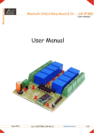
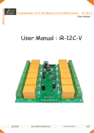
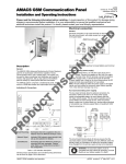
iknowvations
RS232 Relay Board-R242
User Manual
Jan 2012
Doc-R242-UM-Rev1.0
iknowvations.in
1/12
iknowvations
RS232 Relay Board-R242
User manual
4 channel RS232 Relay Board with 9 Digitlal/Analog I/O
Rs232 Data Acquisition Card
Welcome to the world of Computer Automation. This RS232 Relay Board - R242 is a perfect companion
for all your computer automation projects. It is RS232 based card having 4 onboard relays for switching
external devices and upto 9 digital & analogue I/Os that will help you to monitor various real world
scenarios using switches & different kind of sensors to monitor many parameters like Temperature,
Pressure, Light, Touch, PH etc. This card is not only good for controlling Relays but a perfect example
for Data Acquisition applications.
It uses existing Com Port ( you can choose the available one), which allows easy communication with
the card. Any programming language that supports serial communications ( C, C#, C++, VB, VB.NET,
Perl, Java etc) can be used to communicate with R242 very easily. Easy to use commands are available
to communicate with R242 which handle various tasks like Switching On/Off of Relays, Controlling
Digital Inputs & Outputs, Getting analog data etc.
The controller provides 4 relay outputs to control various electrical devices. Apart from this, the card
has up to 9 digital input & output pins. It has also got 4 Analog input pins. All pins can be individually
configured as Digital Input or Digital output on the fly. All analog pins can be individually configured as
digital I/Os also while taking care of input conditions.
Each Digital pin can support a TTL or Schmitt Trigger Input or a 5V output. Each Analog pin will convert
analog voltage ( Between 0 to 5V) or Higher ( through voltage divider) into 10 bit resolution raw data.
This can be converted into required form using conversion formulas.
Any kind of sensor wether it is providing digital output or analogue output can be interfaced with R242
and monitored with the help of computer.
Get windows drivers, test applications and sample codes at http://iknowvations.in
Manufactured by Iknowvations
Rajivnagar,Vidyanagar
Hubli - 580021
India.
Jan 2012
Doc-R242-UM-Rev1.0
iknowvations.in
2/12
iknowvations
RS232 Relay Board-R242
User manual
Relay Outputs
Relay2
Relay1
Relay4
Relay3
Relay On LEDs
12 V DC
Input
Power On
LED
Gnd
Rs232 connector
I/O Port
+5V
Ch1
Ch9
Technical Specifications No. Of Relays
- 4.
Relay Specifications - Coil Voltage 12V Dc. Contact capacity - 5A Max.
Digital Inputs
- Up to 9.
Analog Inputs
- Up to 4.
Supply voltage
- 12 V Dc.
Analog In Volts
ADC Resolution
- 0-5V Dc.
- 10 bits.
Please Read Carefully
This device R242 connects to RS232 port of your computer and can be used to control external devices
through its relays. Incorrect use or faulty board can cause damage to controller itself or Serial Port
controller of your computer or Motherboard of your computer. Extreme care should be taken while using
this board. It will be totally user’s responsibility for the use of this card.
Iknowvations, it’s employees, suppliers, distributors, dealers and/or resellers are not liable to any kind of
damage or loss of data as a result of use of this device, including special, incidental, or consequential damages
resulting from the use of this device or under any legal theory, including loss of profits, downtime, goodwill
damage to, or replacement of equipment or property and any cost for recovering or reproducing any data
stored in computers connected with this device.
Your purchase and/or use of this board indicates your acceptance of these terms.
Jan 2012
Doc-R242-UM-Rev1.0
iknowvations.in
3/12
iknowvations
RS232 Relay Board-R242
User manual
Command Reference 1. For Digital Outputs -
SO10 - Set Output of Channel 1 to 0.
SO11 - Set Output of Channel 1 to 1.
There are up to 7 digital Output channels on this card so it will be up to SO70 & SO71.
GI01 - Get Input value of Channel 01.
GI02 - Get Input value of Channel 02.
There are up to 9 digital Inputs channels on this card so it will be up to GI09.
2. For Digital Inputs -
ADC1 - Get ADC value of Channel 1.
ADC2 - Get ADC value of Channel 2.
There are up to 4 Analog channels on this card so it will be up to ADC4. The resolution is
of 10 bits so the input voltage ( 0-5V Dc) will be converted to 0 to 1023 Decimal value.
3. For Analog Inputs
-
RL10 - Make Relay 1 Off.
Rl11 - Make Relay 1 On.
There are 4 Relays on this card so it will be up to RL40 & Rl41. There are 2 additional commands
for relays RLA0 - Make All Relays Off.
RLA1 - Make All Relays On.
I1XX - XX in Hex
5. Setting I/O channels1000 0000 - bit7 bit6 bit5 bit4
bit3 bit2 bit1 bit0
1
Ch7 Ch6 Ch5
Ch4 Ch3 Ch2 Ch1
1- for pin to be output, 0- for pin to be input
6. Miscellaneous Commands BORD - Issuing this command will return the card Number.
VERS - Issuing this command will return the Firmware Version Number.
GTI1 - Get Set value of I/O channels.
4. For Relay Outputs
-
Channel 1 - CH1 - Input / Output / ADC 1
Channel 2 - CH2 - Input / Output / ADC2
Channel 3 - CH3 - Input / Output / ADC3
Channel 4 - CH4 - Input / Output / ADC4
Channel 5 - CH5 - Input / Output
Channel 6 - CH6 - Input / Output
Channel 7 - CH7 - Input / Output
Channel 8 - CH8 - Input only
Channel 9 - CH9 - Input only
Please note that all the input channels have weak pull up enabled all the time and after first
time connection of card the channel setting will be FF that is all channels will be outputs. All
the output pins will be 0 that is will be low at this time.
Using the card - R242You can connect the card with your computer using any serial port cable. You have also to apply
power 12 V Dc to Barrel connector ( center +ve).
You can communicate with the card through Hyper Terminal Software which generally every
computer has pre installed or you can use iKantrol-R242 - a special software made by Iknowvations
( you can download it free from our website iknowvations.in) or you can develop your own software.
Jan 2012
Doc-R242-UM-Rev1.0
iknowvations.in
4/12
iknowvations
RS232 Relay Board-R242
User manual
Now let us see how we can communicate with R242 with the help of iKantrol-242.
Connect R242 card with Rs232 cable & power it.
Start iKantrol-R242.
You will get following screen on your computer.
Select the com port to which you have connected the card R242 from available com port
list. Press connect button. If the card is connected you will get next screen with all the
buttons enabled in blue panel.
If card is not connected or powered up you will get following message -
Check the cable & power then connect again.
Jan 2012
Doc-R242-UM-Rev1.0
iknowvations.in
5/12
iknowvations
RS232 Relay Board-R242
User manual
If the card is connected, you will have following screen.
If you change any setting of Channels the Set I/O button color will change to red from green. To
make change click the Set I/O button. It will turn into green again after setting the latest value,
which is also shown above the button both in Decimal & Hex form.
Please not that all the buttons will be enabled or disabled as per I/O channel setting.
Jan 2012
Doc-R242-UM-Rev1.0
iknowvations.in
6/12
iknowvations
RS232 Relay Board-R242
User manual
Here is a screen shot showing raw value of ADC channel 1 & 3. Also note that buttons of
ADC channel 2 & 4 are disabled as the respective channels are set as Outputs.
If you want to communicate with the card via HyperTerminal then start the HyperTerminal &
set the com values as per following screen shot.
Select the com port as per your connection to the card.
Apply the power to the card. You will be greeted with the welcome message and the
prompt “>”.
Jan 2012
Doc-R242-UM-Rev1.0
iknowvations.in
7/12
iknowvations
RS232 Relay Board-R242
User manual
Type HELP and press Enter. This is the way to enter any command. Please note that all the
commands are entered in CAPs followed by Enter button. HELP command shows all the available
commands & short along with their short description.
Screen shot showing various other commands.
Jan 2012
Doc-R242-UM-Rev1.0
iknowvations.in
8/12
iknowvations
RS232 Relay Board-R242
User manual
Screen Shots showing Relay commands & ADC channel commands.
Using Relay Outputs Relay outputs can be used to operate various electrical devices under software control. Extreme
care should be taken if you are using 110 or 230 V AC. Iknowvations will not be responsible for any
kind of damage or loss whatsoever to life or property. It will be totally user’s responsibility.
NC - Normally closed contact - connected with common when relay is off. Disconnected while on.
C - Common contact.
NO- Normally open contact - connects with common when relay is on. Disconnected while off.
110 or 230V AC Live
Neutral
Use of RC Snubber Circuit across relay contacts is recommended to avoid electrical interference.
Jan 2012
Doc-R242-UM-Rev1.0
iknowvations.in
9/12
iknowvations
RS232 Relay Board-R242
User manual
Using Input channels Input channels can be used to monitor input conditions of any signal that toggles between 0 and 1,
that is between High & Low. Following is one of the ways to monitor input value - Key inputs.
+ 5 V DC
Resistor
To Input channel
Press to on key
GND
Using ADC channels ADC channels can be used to monitor input voltages of any signal that varries between 0 and 5V Dc.
Following is one of the ways to monitor ADC input value.
+ 5 V DC
+ 5 V DC
Variable Resistor
GND
Any sensor providing
analog output 0-5 V Dc.
To Input channel
GND
Using Output channels Output channels can be toggled between 1 & 0, that is bet High & Low. This signal can be used to
switch on & off through use of transistor shown as under + 5/9/12 V Dc
+5V
Resistor
Led
Resistor
Jan 2012
Npn Transistor
Doc-R242-UM-Rev1.0
Relay
Resistor
Diode
Npn Transistor
iknowvations.in
10/12
iknowvations
RS232 Relay Board-R242
User manual
If you have any questions, want any assistance, want us to develop any special products for you
just contact us at [email protected].
We have other products also that might interest you like -
Just like R242, U452 is an USB
based Relay Card having up to 16
I/O channels & 8 ADC channels.
The ADC resolution is 8/10/12 bits
user selectable.
Experimental Board for TI LaunchPad.
6 digit 7 segment Multipurpose LED Counter
For more information visit - www.iknowvations.in
For experiments & other technical knowledge do read our blog at www.iknowvations.in/blog/
Jan 2012
Doc-R242-UM-Rev1.0
iknowvations.in
11/12
iknowvations
RS232 Relay Board-R242
User manual
Please Read Carefully
Information in this document is provided solely in connection with Iknowvations products. Iknowvations reserrve the right to make
changes, corrections, modifications or improvements, to this document, and the products and services described herein at
anytime, without notice.
All Iknowvations products are sold pursuant to Iknowvations terms and conditions of sale.
Purchasers are solely responsible for the choice, selection and use of the Iknowvations products and services described herein,
and Iknowvations assumes no liability whatsoever relating to the choice, selection or use of the Iknowvations products and services
described herein.
No license, express or implied, by estoppel or otherwise, to any intellectual property rights is granted under this document.
If any part of this document refers to any third party products or services it shall not be deemed a license grant by Iknowvations for
the use of such third party products or services, or any intellectual property contained therein or considered as a warranty
covering the use in any manner whatsoever of such third party products or services or any intellectual property contained
therein.
UNLESS OTHERWISE SET FORTH IN IKNOWVATIONS’S TERMS AND CONDITIONS OF SALE IKNOWVATIONS DISCLAIMS ANY EXPRESS
OR IMPLIED WARRANTY WITH RESPECT TO THE USE AND/OR SALE OF IKNOWVATIONS PRODUCTS INCLUDING WITHOUT
LIMITATION IMPLIED WARRANTIES OF MERCHANTABILITY, FITNESS FOR A PARTICULAR PURPOSE (AND
THEIR EQUIVALENTS UNDER THE LAWS OF ANY JURISDICTION), OR INFRINGEMENT OF ANY PATENT,
COPYRIGHT OR OTHER INTELLECTUAL PROPERTY RIGHT.
UNLESS EXPRESSLY APPROVED IN WRITING IKNOWVATIONS PRODUCTS ARE NOT RECOMMENDED, AUTHORIZED OR WARRANTED FOR
USE IN MILITARY, AIR CRAFT, SPACE, LIFE SAVING, OR LIFE SUSTAINING APPLICATIONS, NOR IN PRODUCTS OR SYSTEMS WHERE FAILURE OR
MALFUNCTION MAY RESULT IN PERSONAL INJURY, DEATH, OR SEVERE PROPERTY OR ENVIRONMENTAL DAMAGE.
Resale of IKNOWVATIONS products with provisions different from the statements and/or technical features set forth in this document
shall immediately void any warranty granted by Iknowvations for the Iknowvations product or service described herein and shall not create
or extend in any manner whatsoever, any liability of Iknowvations.
Information in this document supersedes and replaces all information previously supplied.
The Iknowvations logo is property of Iknowvations.in. All other names are the property of their respective owners.
c 2012
Iknowvations - All rights reserved
www.iknowvations.in
Jan 2012
Doc-R242-UM-Rev1.0
iknowvations.in
12/12