1
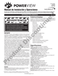
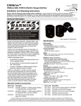
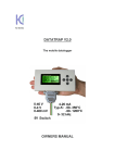
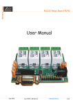
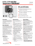
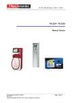
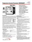
AMACS GSM Communication Panel
yi6359
th
revision E, 4 May 2007
catalogue section 30
Installation and Operating Instructions
Please read the following information before installing. A visual inspection of this product for damage during
shipping is recommended before installation. It is your responsibility to ensure that qualified mechanical and
electrical technicians install this product. If in doubt, please contact your local Murphy representative.
Electrical connection
E
D
General
Electrical connection is via screw terminals on the lower edge of
the main circuit board, with cable access by a removable cover
in the panel base:-
input input
2 (B) 1 (A)
+
NO
C
+
+
–
–
+
–
–
O
N
T
NC
NO
C
DC
input
IN
aux
input
U
AMACS circuit board
relay relay
output output
fuse
2 (B) 1 (A)
+12V
0V
Description
Use a 3mm flat-head screwdriver to loosen/tighten each terminal
connection.
General
DC input (primary power supply)
AMACS is powered from a 12 volts DC supply (9.5v min to
14v max range). Connect the negative or zero volt (0v) supply
to the ‘–‘ terminal of the ‘DC IN’ terminals; connect the positive
(+12VDC) supply to the ‘+’ terminal of the ‘DC IN’ terminal.
A power supply fuse is fitted on the circuit board above the DC
supply terminals (see specification for fuse rating).
Note: The DC voltage for either the power supply or the digital
inputs must not exceed the maximum stated values (typically
14.0 v DC) otherwise damage may occur.
IS
C
The AMACS GSM (Advanced Monitoring And Control Systems)
panel is an input/output control device capable of 2-way
communication with a user’s mobile phone. The system can
be used for status monitoring, fault notification and control of
remote, vital equipment. Set-up and control of the AMACS
panel is entirely by mobile phone SMS text commands.
The AMACS system comprises a weatherproof panel, inside of
which is a GSM data modem and input/output circuit board:-
D
T
C
Typical connection is:-
1A fuse
DC
input input
2 (B) 1 (A)
+
aux
+
–
O
+
D
+
D
send / receive
–
power/
watchdog
The Aux input terminals allow the optional connection of a
secondary 12VDC (9.5v min to 14v max) power supply,
usually a rechargeable battery of lower capacity than the
‘DC input’ primary supply. The Aux input is typically used to
power AMACS for short periods of time, when the primary
supply is either out of normal limits (e.g. during engine cranking)
or unavailable (e.g. following supply failure or equipment theft).
–
U
network signal
strength
Aux input (secondary power supply)
–
Indications & Connections
R
F1
P
secondary +12V
battery
supply 0V
Power/Watchdog
Illuminates when DC is applied to the unit.
Flashes when the AMACS develops a fault.
Network Signal
Indicates GSM network signal strength (see
set-up and operation for details).
Send/Receive
Illuminates when the AMACS is sending or
receiving SMS text messages. Flashes
when there is no mobile phone number in
the configuration.
Table 1: LED indicator description
General product specifications and overall/mounting dimensions
can be found on page 4 of this document.
AMACS GSM installation and operation
primary +12V
DC / battery
supply 0V
The circuit board blocking diode (D above) ensures that the
secondary battery powers AMACS (and only AMACS) when the
primary supply is unavailable, but allows the secondary battery
to be charged from the primary supply during normal operation.
WARNING: the secondary battery must be
compatible with this method of recharging. Consult
Murphy or your battery supplier if in doubt.
yi6359 revision E 4th May 2007 p1/4
The current rating of quick-blow fuse F1 must be chosen in
relation to the maximum charge current of the secondary battery,
but should not be more than 1 Amp (the maximum current rating
of the internal blocking diode).
One AMACS input may be configured to send a text message
warning when the primary supply fails (e.g. due to a battery
charging fault or equipment theft). For example, connect input
2(B) across the primary supply (shown by dashed lines in the
connection diagram above); then set AMACS to send a suitable
text message when input 2(B) goes ‘low’. (A typical set-up
command might be “IPBLPRIMARY DC FAIL” – see Set-up
and Operation below for general set-up information.)
Text message commands 1 to 6 above are typically used before
panel commissioning to set up dial-out phone numbers and dialout (fault/status) messages. Messages 7 to 13 are typically sent
in normal operation, to energise, de-energise or pulse relay
outputs and request a panel status update.
Before any set-up or control commands can be sent, the AMACS
panel must:a) be powered up. The ‘Power/Watchdog’ LED illuminates
constantly when DC power is applied, and
Digital (switch) inputs
AMACS has two inputs, which are typically used for monitoring
equipment status or faults. The system can be set to notify the
user’s mobile phone when either input goes ‘high’ and/or ‘low’
(a separate text message for each input transition). The inputs
are designed for use with remote contacts that close to battery
positive (input ‘high’) or go open circuit (input ‘low’).
The lighting or flashing of the LED determines the strength of the
network signal:-
Relay output 1(A)
Relay output 2(B)
D
Table 2: Power & Input requirements
Set-up and Operation
General
D
U
C
T
Set-up and control of the AMACS panel is entirely by text
message commands sent from any mobile phone. Each AMACS
panel has a unique mobile phone number, one or more of which
may be programmed into the address book of the user’s mobile
phone (each with an appropriate name). To remotely set-up or
control an AMACS system, the user selects the name/number
of the intended system, then sends that number a text message
command. The following is a summary list of commands:Message format
Set the primary dial out phone number
TELA0123456789
Set the secondary dial out phone number
TELB987654321
O
Operation
P
R
Set Input 1(A) Low to High text description
default message = “Event1”
Set Input 1(A) High to Low text description
default message = “Event1”
Set Input 2(B) Low to High text description
default message = “Event2”
Set Input 2(B) High to Low text description
default message = “Event2”
Turn relay 1(A) ON
Turn relay 1(A) OFF
Turn relay 1(A) ON for a 5 second pulse
Turn relay 2(B) ON
Turn relay 2(B) OFF
Turn relay 2(B) ON for a 5 second pulse
Request input, output and credit status
AMACS GSM installation and operation
IPAHabcdefgh
IPALabcdefgh
IN
U
Permanently on:
Full Signal Strength
If the LED is not illuminated then there is insufficient signal
strength for the unit to function correctly. To correct this problem,
move the AMACS panel to a location that has greater signal
strength or, if this is not possible, fit an antenna extension cable
that will improve signal reception.
Network signal strength is acceptable even at the short pulse
signal indicated by the network signal LED. Once acceptable
signal strength has been obtained the AMACS GSM can be
programmed and controlled to the user’s requirements.
IS
Inputs
1(A) and 2(B)
12 volts DC (9.5v – 14.0v)
0 volts DC
Switched +12 volts DC
0 volts DC
Normally Closed contact
Normally Open contact
Common
Normally Open contact
Common
ON
OFF
Equal Length Flashes:
Good Signal Strength
C
Input/output specifications
ON
OFF
O
N
T
AMACS has two relay outputs: output 1 has SPDT (changeover)
contacts; output 2 has SPNO (normally open) contacts. Both
outputs have volt-free (dry) contacts that will switch up to
3 Amps at 240 volts AC or 3 Amps at 24 volts DC. The remote
user can send mobile phone SMS text commands to energise,
de-energise or ‘pulse’ each relay output, which in turn may be
used to control the remote equipment (e.g. a fault reset contact,
or a motor/pump start signal).
+
–
+
–
NC
NO
C
NO
C
Short Flashes:
Poor Signal Strength
ON
OFF
Relay outputs
DC power input,
Aux input
E
D
b) have acceptable Network reception strength, as indicated
by the ‘Network Signal’ indication LED on the circuit board.
Note: It may take a short time for the system to find and detect
the GSM network - once the network LED illuminates the system
is ready to operate.
WARNING: correct set-up and operation is
dependent on a minimum level of network signal
strength. Murphy cannot accept responsibility or
liability for operating failures caused by poor
network signal.
Set-up procedure and commands
Step 1 – Identify AMACS phone number
Read the AMACS GSM device mobile phone number,
which is located on the rating plate within the unit enclosure.
This number should be stored in the user’s mobile phone
with a name that is relevant to the location/operation of the
AMACS unit, e.g. ‘Pump 1’, ‘Diesel Tank’, ‘Hopper No2’ etc.
Step 2 – Set primary phone number
When an input activates (e.g. during an alarm), or if a ‘status
update’ command is received, the AMACS panel can be set to
dial out to a primary phone number. The number must be that
of a mobile phone capable of receiving SMS text messages.
The primary dial-out number is set in the AMACS unit by
sending an SMS text message in the format below:To set a primary (A) number of 01234 567890, send command:TELA01234567890
IPBHabcdefgh
The Send/Receive LED should briefly flash to indicate reception
of the command.
IPBLabcdefgh
Important Note: the phone number segment of the text
command must be in one of the following formats: -
RLA1
RLA0
RLAP
RLB1
RLB0
RLBP
STAT
077961234567 – UK dialling format
4477961234567 – International Dialling Format
When entering the international format, do not place the ‘+’ in
front of the phone number.
yi6359 revision E 4th May 2007 p2/4
Step 3 – Set secondary phone number
Requesting AMACS status
If the user wishes to know the status of a particular AMACS unit,
send the AMACS the text command:-
After an input activation/deactivation or status message
has been sent to the primary number, the AMACS may be
optionally set to send the same message to a secondary
number.
STAT
Once AMACS has received this command, it will dial out to the
primary number (and secondary number if programmed) and
leave a text message in the following format:-
To set a secondary (B) number of 09876 543210, send command:TELB09876543210
IP-AN OP-ED
IP=Inputs (A=Active, N=Non active)
OP=Outputs (E=Energised, D=De-energised)
0123456789
9876543210
Event 1 High
Event 1 Low
Event 2 High
Event 2 Low
Remaining Credit #1.25
Nominated Primary and
Secondary phone numbers(s)
The Send/Receive LED should briefly flash to indicate reception
of the command.
Step 4 – Set inputs 1 & 2 description & operation
Each AMACS input (1 or 2) may be programmed with one or two
text descriptions, allowing a relevant message to be sent back to
remote mobile phone(s) in the event of input activation and/or
de-activation. The text descriptions are programmed into
AMACS by sending text commands in the following formats:-
U
O
N
T
Low Credit alarm
The AMACS GSM can detect how much credit remains on the
SIM card and will warn the user (by text message) if the credit
gets too low.
AMACS requests credit information from the network operator
whenever DC power is applied to the unit and thereafter at 24
hour intervals. If (at each credit check) the remaining credit is
below £1, AMACS will dial out to the primary phone number
with a warning that the credit is at a low level and will need to
be ‘Topped-up’. To prevent subsequent warnings at 24 hour
intervals (assuming the panel remains powered up), prompt
action should be taken to top-up the SIM card credit.
C
Note: If no input 1 program commands are sent to the AMACS
unit, the default text of ‘Event 1’ is used (is sent out as a
notification message) for both input activation and deactivation.
Output tracking status
IN
Other features
For AMACS to send a “Pump stopped” message when input 1(A)
goes ‘low’ (from 12v DC to 0v DC), send program command:IPALPump Stopped
To inhibit any dial out or message when input 1(A) goes ‘low’
(from 12v DC to 0v DC), send the program command:IPAL
Digital Input text description(s)
The value of remaining credit (in Pounds Sterling) is based on a
Pay-As-You-Talk SIM card. If a contract based SIM card is used
in the modem the unit will not return a value of credit left.
For AMACS to send a “Pump running” message when input 1(A)
goes ‘high’ (from 0v DC to 12v DC), send program command:IPAHPump Running
To inhibit any dial out or message when input 1(A) goes ‘high’
(from 0v DC to 12v DC), send the program command:IPAH
E
D
The secondary number operates in a similar way to the primary
number, but is programmed into the AMACS using the following
text command:-
IS
Text descriptions for Input 2(B) activation and/or deactivation
may be programmed into AMACS using command formats as
above but with prefixes IPBH or IPBL.
D
For each program command sent, the AMACS Send/Receive
LED should briefly flash to indicate reception of the command
message.
Control Commands
T
After set-up is complete, text commands from the user’s mobile
phone can be used for two AMACS control features:-
C
• Energising, de-energising or pulsing either relay output
• Requesting the AMACS ‘status’
D
U
Operating the relay outputs
Energisation, de-energisation or pulsing of each AMACS relay
can be achieved by mobile phone text commands in the
following format:-
Note: If during normal use a ‘status’ request is made and there
is no reply, it may be that the credit has expired and there is
insufficient credit to permit sending a SMS text message to
indicate the status.
The user can top up the credit on the SIM card without going
to the unit or using that SIM card. Credit can be applied to the
SIM card from any landline phone or mobile phone. Follow the
instructions on the network ‘Top-up’ card available at
supermarkets, post offices etc.
Pay-As-You-Talk SIM card replacement
The AMACS GSM comes complete with a Pay-As-You-Talk mini
SIM card on the Vodafone network suitable for operation within
the United Kingdom and Europe. If the modem SIM card needs
to be replaced the following procedure should be adhered to.
Important: Turn the DC power to the AMACS unit OFF and then
eject the SIM cardholder.
O
To energise (turn ON) relay 1, send the text message:RLA1
Push button to eject
SIM holder
R
To energise (turn ON) relay 2, send the text message:RLB1
P
To de-energise (turn OFF) relay 1, send the text message:RLA0 (note: 0 = zero)
SIM Card Slot/Tray
To de-energise (turn OFF) relay 2, send the text message:RLB0 (note: 0 = zero)
To pulse (turn ON) relay 1 for 5 seconds only, send message:RLAP
Locate the replacement SIM in the holder (1) and put the tray
back into the modem (2). Turn on the DC power to the unit.
SIM Card
To pulse (turn ON) relay 2 for 5 seconds only, send message:RLBP
Note: Pulse commands RLAP and RLAB only operate as
described above when the relay is already de-energised.
If a command is sent to an already energised relay, the relay will
de-energise 5 seconds after receiving the command (without any
subsequent pulse or re-energisation).
AMACS GSM installation and operation
SIM Card Holder
yi6359 revision E 4th May 2007 p3/4
Specifications
Electrical & Network Characteristics
9.5 to 14 V DC
80mA (quiescent), <200mA (during GSM receive and transmit)
Integral fuse (on circuit board), 1 Amp fast blow (20 x 5)
Inputs
Outputs
Network Suitability
SIM Card
2 digital (switch) inputs: 12 volts DC
2 relay outputs (1 x normally open, 1 x Change over), rated 3A@240VAC or 3A@24VDC
Suitable for all dual band GSM networks: O2, Vodafone, Orange and T-Mobile.
Mini SIM card for GSM network
Dual band coverage suitable for UK, Europe, Asia and Far East.
(Excludes North and South American continents)
E
D
DC supply voltage
DC supply current
Fusing
300mm (+120mm for antenna) x 200mm x 150mm (details below)
-10ºC to +50ºC
IP54 with correct glanding at cable entry
Mounting
Weight
Wall mounted via internal fixings
5.5Kg
O
N
T
IN
Dimensions (max) H x W x D,
Temperature range
Protection class
U
Mechanical Characteristics
IS
C
Dimensions
120
GSM Coverage
T
D
U
C
260
AMACS PCB
300
TC35T
MODEM
D
7.0
fuse
P
R
O
elecrical connections
160
Fixing dimensions
200
External dimensions and internal layout
FRANK W MURPHY LTD.
Church Road, Laverstock, Salisbury, SP1 1QZ, United Kingdom
tel: +44 (0)1722 410055 fax: +44 (0)1722 410088
email: [email protected] web: www.fwmurphy.co.uk
In order to consistently bring you the highest quality, full featured products, we reserve the right to change our specifications and designs at any time.
AMACS GSM installation and operation
yi6359 revision E 4th May 2007 p4/4