1
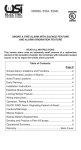
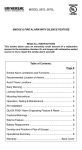
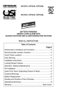
MODEL MCN108, MCN108L CARBON MONOXIDE ALARM AND NATURAL GAS ALARM WITH SILENCE FEATURE 120VAC 60 Hz 100 mA Max. MODEL MCN105, MCN105L CARBON MONOXIDE ALARM AND SECURITY INSTRUMENTS, INC. NATURAL GAS ALARM WITH SILENCE FEATURE 120VAC 60 Hz 100 mA Max. PLEASE READ AND SAVE! THANK YOU for purchasing this combination alarm. This manual includes important information regarding where to install the alarm, how to operate, maintenance, testing and product features. It also includes tips and information which could help protect you and your family. Table of Contents: Page # What You Should Know About CO ........................................................ 2 What You Should Know About Natural Gas .......................................... 2 Recommended Location of Alarms ....................................................... 2 Basic Safety Information ....................................................................... 3 Where Alarm Should Not Be Installed .................................................. 4 Installation Instructions ......................................................................... 5 Electrical Shock Hazard ........................................................................ 5 Locking / Tamper Feature ................................................................. 5, 6 Wiring Instructions ................................................................................ 6 Operation, Testing & Maintenance ........................................................ 7 QUICK FIND® Alarm Originating Feature & Reset ................................ 8 What To Do If The Alarm Sounds ......................................................... 8 CO Alarm Silence Feature .................................................................... 9 Testing & Maintenance .................................................................... 9, 10 Battery Backup Replacement ............................................................. 10 CO & Natural Gas Alarm Limitations ................................................... 11 Operational Summary ................................................................... 12, 13 Warranty ............................................................................... Back Cover WHAT YOU SHOULD KNOW ABOUT CO Carbon monoxide (CO) is an insidious poison. It is a colorless, odorless, tasteless gas. It is a cumulative poison. Even low levels of CO have been shown to cause brain and other vital organ damage in unborn infants with no effect on the mother. The following symptoms are related to CARBON MONOXIDE POISONING and should be discussed with ALL members of the household: MILD EXPOSURE Slight headache, nausea, vomiting, fatigue (often described as "flu-like" symptoms). MEDIUM EXPOSURE Severe throbbing headache, drowsiness, confusion, fast heart rate. EXTREME EXPOSURE Unconsciousness, convulsions, cardiorespiratory failure, death. Many cases of reported CARBON MONOXIDE POISONING indicate that victims are aware they are not well, but they become so disoriented that they are unable to save themselves by either exiting the building or calling for assistance. Young children and household pets may be the first affected. Your combination alarm is designed to detect the toxic CO fumes that result from incomplete combustion, such as those emitted from appliances, furnaces, fireplaces and auto exhaust. What Levels of CO Cause an Alarm? Underwriters Laboratories Inc. UL2034 defines three specific alarm points by which all residential CO alarms must alarm. They are measured in parts per million (ppm) of CO over time (in minutes). UL2034 Required Alarm Points: • If the alarm is exposed to 400 ppm of CO, IT MUST ALARM BETWEEN 4 and 15 MINUTES. • If the alarm is exposed to 150 ppm of CO, IT MUST ALARM BETWEEN 10 and 50 MINUTES. • If the alarm is exposed to 70 ppm of CO, IT MUST ALARM BETWEEN 60 and 240 MINUTES. This product is intended for use in ordinary indoor locations of family living units. It is not designed to measure compliance with Occupational Safety and Health Administration (OSHA) commercial or industrial standards. Individuals with medical problems may consider using warning devices which provide audible and visual warnings for carbon monoxide concentrations under 30 ppm. IMPORTANT CONSIDERATIONS YOUR COMBINATION CO AND NATURAL GAS ALARM HAS BEEN DESIGNED WITH A PRODUCT END-OF-SERVICE LIFE SIGNAL WHICH WILL SOUND AFTER APPROXIMATELY 7 YEARS OF OPERATION FROM INITIAL POWER UP. NOTE: MANUFACTURER RECOMMENDS REPLACEMENT OF THIS ALARM 7 YEARS AFTER DATE OF INSTALLATION. WHAT YOU SHOULD KNOW ABOUT NATURAL GAS Natural gas is a fossil fuel which consists primarily of methane. This common energy source is often used for cooking, home heating and water heating. Natural gas is typically supplied through a main utility line connected to your home. It is a highly flammable chemical compound. Although it happens rarely, a natural gas leak can sometimes occur inside the home. This can be dangerous because it increases the risk of explosion and fire. Natural gas is odorless and colorless. When Mercaptan is added to natural gas as an odorant, it can then be detected by smell. Although it can vary greatly, the typical level for detection of the gas by smell is 25% of the lower explosion limit (LEL). People who have a diminished sense of smell may not be able to rely on this safety mechanism. Therefore, installation of this alarm can be an important tool to help protect you and your family. This alarm is calibrated to sound before 20% LEL Therefore, it is possible that you may smell gas before the alarm is activated. If you are not sure which gas your home uses, contact your utility company. Natural gas (methane) is typically supplied through a main utility line connected to your home. Early warning is best achieved by the installation of alarms on all floors and areas of the household. WHERE THIS CO AND NATURAL GAS ALARM SHOULD BE INSTALLED • Install an alarm inside each bedroom where the occupant closes the door while sleeping. Page 2 • An alarm should be installed in any family living unit containing a fuel-burning appliance or fireplace or having an attached garage. • An alarm should be centrally located outside of each separate sleeping area in the immediate vicinity of the bedrooms. Where bedrooms are separated and audibility of the alarm to occupants within the bedroom area could be seriously impaired, more than one alarm could be needed. • Locate the first combination alarm in the immediate area of the bedrooms. Try to protect the escape route as the bedrooms are usually farthest from an exit. If more than one sleeping area exists, locate additional combination alarms in each sleeping area. If a hall is more than 40 feet (12 meters) long, install a combination alarm at each end. • Locate at least one combination CO and Gas alarm on every floor level. In general, install combination CO and Gas Alarms: • WHERE YOU CAN HEAR THE ALARM FROM ALL SLEEPING AREAS. • In or near bedrooms and living areas or wherever you suspect a natural gas or CO exposure is likely. • On each level of a multilevel home. IMPORTANT! Installation in an improper location can affect the sensitive electronic components in this alarm. Please review WHERE THIS ALARM SHOULD NOT BE INSTALLED (see Page 4). Not suitable for installation in hazardous locations as defined in the National Electrical Code. This alarm will detect natural gas primarily and carbon monoxide secondarily. Natural gas events will always take precedence over carbon monoxide events. The word "gas" will be used to specifically refer to natural gas. When on AC power, this alarm is designed to act as a continuous monitor. It is not designed for use as a short-term testing device to perform a quick check for the presence of CO or gas. BASIC SAFETY INFORMATION • This combination Carbon Monoxide and Natural Gas alarm has separate alarms. This alarm is not designed to detect smoke, heat or any other gas. Carbon monoxide and natural gas may be present in other areas. The CO and Natural Gas Alarm will only indicate the presence of CO or natural gas which reaches the sensor. • Do not paint the alarm. Paint may clog the openings to the sensing chambers and prevent the unit from operating properly. • Do not stand too close to the unit when the alarm is sounding. It is loud to wake you in an emergency. Exposure to the horn at close range may harm your hearing. Make sure the alarm is not receiving excessively noisy power. Examples of noisy power could be major appliances on the same circuit, power from a generator or solar power, light dimmer on the same circuit or mounted near fluorescent lighting. Excessively noisy power may cause damage to your alarm. This alarm cannot be operated from power derived from a square wave, modified square wave or modified sine wave inverter. These types of inverters are sometimes used to supply power in off-grid installations, such as solar or wind derived power sources. These power sources may produce high peak voltages which will damage the alarm. Do not install this alarm into an electrical circuit controlled by a dimmer or switch or ground fault circuit interrupter. RECOMMENDED PLACEMENT: Page 3 NOTE: For any location, make sure no door or other obstruction could prevent the carbon monoxide or gas from reaching the alarm. WHERE THIS ALARM SHOULD NOT BE INSTALLED To avoid causing damage to the unit, to provide optimum protection, and to prevent unnecessary alarms. Do NOT locate this alarm: • In garages, kitchens, crawl spaces and unfinished attics. Avoid extremely dusty, dirty or greasy areas. Installation in these areas could lead to nuisance alarms, may expose the sensor to substances which could damage or contaminate it, or the alarm may not be heard by people in other areas of the home, especially if they are sleeping. • In the garage, vehicle exhaust can contain some carbon monoxide. These levels are higher when the engine is first started. Within hours of starting a vehicle and backing it out of the garage, the levels present over time can activate the alarm and become a nuisance. • In the kitchen, some gas appliances can emit a short burst of CO or gas upon startup. This is normal. If your CO and Natural Gas Alarm is installed too close to these appliances, it may alarm often and become a nuisance. • Keep alarms at least 20 feet (6m) from the sources or combustion particles (stove, furnace, water heater, space heater), if possible. In areas where a 20 foot (6m) distance is not possible (in modular, mobile or smaller homes for example), it is recommended the alarm be placed as far from these fuel-burning sources as possible. The placement recommendations are intended to keep these alarms at a reasonable distance from a fuel-burning source and reduce "unwanted" alarms. Unwanted alarms can occur if an alarm is placed directly next to a fuel-burning source. Ventilate these areas as much as possible. If you must install the alarm near a cooking or heating appliance, install at least 5 feet (1.5m) from appliance. • Less than 12 inches (306mm) away from fluorescent lights. Electrical noise can interfere with the sensor. • In extremely humid areas. This alarm should be at least 10 feet (3m) from a bath or shower, sauna, humidifier, vaporizer, dishwasher, laundry room, utility room or other source of high humidity. • In very cold or very hot environments or in unheated buildings or outdoor rooms where the temperature can go below or above the operating range of the alarm. Temperature limits for proper operation are 40o to 100oF (4.4o to 37.8oC). • In turbulent air, such as near ceiling fans, heat vents, air conditioners, fresh air returns or open windows. Blowing air may prevent CO or natural gas from reaching the sensors. • Good ventilation is recommended when household cleaning supplies or similar contaminants are used. • Excessive spillage or reverse venting of fuel-burning appliances caused by outdoor ambient conditions, such as: Wind direction and/or velocity, including high gusts of wind. Heavy air in the vent pipes (cold/ humid air with extended periods between cycles). Negative pressure differential resulting from the use of exhaust fans. Simultaneous operation of several fuel-burning appliances competing for limited internal air. Vent pipe connections vibrating loose from clothes dryers, furnaces or water heaters. Obstructions in or unconventional vent pipe designs which can amplify the above situations. Page 4 THIS ALARM WILL NOT WORK WITHOUT 120 VAC POWER AND A GOOD BATTERY PROPERLY INSTALLED. THE ALARM SHOULD BE TESTED WHEN INSTALLED AND THEN TESTED WEEKLY AFTER THAT. INSTALLATION INSTRUCTIONS: CAUTION!! READ CAREFULLY. Installation of this alarm must conform to the electrical codes in your area; Article 760 of the National Electrical Code, NFPA 72, 101; SBC (SBCCI); UBC (ICBO); NBC (BOCA): OTFDC (CABO), and any other local or building codes that may apply. Wiring and installation must be performed by a licensed electrician. Failure to follow these guidelines may result in injury or property damage. This alarm must be powered by a 24-hour, 120V AC 60Hz circuit. Be sure the circuit cannot be turned off by a switch, dimmer or ground fault circuit interrupter. Failure to connect this alarm to a 24-hour circuit may prevent it from providing constant protection. IMPORTANT: Do not subject this alarm to megger, high voltage or high-pot tests. Remove the alarm(s) before high-potting tests occur on the circuit or system. (Ref. Section 550-17, National Electrical Code, 2002 Edition). ELECTRICAL SHOCK HAZARD Turn off power to the area where you will install this alarm at the circuit breaker or fuse box before beginning installation. Failure to turn off the power before installation may result in serious electrical shock, injury or death. CAUTION: THIS CO AND NATURAL GAS ALARM IS SEALED. THE COVER IS NOT REMOVABLE! • A mounting bracket is provided on the back of the alarm. • Remove the mounting bracket from the back of the alarm by holding the mounting bracket and twisting the alarm in the direction indicated by the "TWIST TO REMOVE" arrow on the side of the alarm base. OPTIONAL TAMPER RESISTANT FEATURES: There are two separate tamper resistant locking features provided for this model. Activating one or both of these features deters someone from removing the alarm from the mounting bracket or removing the battery from the alarm. The breakaway locking pins are clearly marked and molded into the mounting bracket. Refer to the diagram on the next page. TO ACTIVATE THE LOCKING FEATURES: Do not activate the locking features until you have activated the battery, mounted the alarm to the bracket and tested the alarm. Refer to OPERATION, TESTING & MAINTENANCE instructions on Page 6. 1. Detach the breakaway alarm locking pin from the mounting bracket. ALARM/BRACKET LOCKING PIN BATTERY LOCKING PIN 2. Insert the pin into the hole for the feature you are activating. Refer to the diagram below for correct placement. INSERT ALARM LOCKING PIN HERE INSERT BATTERY LOCKING PIN HERE TO DEACTIVATE THE LOCKING FEATURES: To remove the alarm for cleaning or servicing or to replace the battery, you must first remove the appropriate locking pin, if it has been installed. 1. Turn off AC power to the circuit. 2. Use long nose pliers to pull the locking pin out of the hole. 3. It is now possible to remove the alarm or replace the battery. WIRING INSTRUCTIONS: 1. a. The appropriate power supply is 120 Volt single phase power supplied from a non-switchable circuit NOT protected by a ground fault circuit interrupter. Page 5 b. c. Turn off AC power to the circuit before wiring the alarm. There are three pigtail wires (black, white and yellow) coming from the AC QUICK CONNECTOR. The proper wire connection is as follows: WIRES FROM QUICK CONNECTORCONNECT TO BLACK "HOT" side of AC line WHITE "NEUTRAL" side of AC line YELLOW Interconnect wires of other alarms DO NOT TAMPER WITH WIRES WHEN POWER IS ON! For alarms that are used as single non-interconnected, stand-alone alarms, do not connect the yellow wire to anything. Insulate this wire (tape it) in place to make certain the yellow wire cannot contact any metal parts. Interconnected alarms can provide earlier warning of fire than stand-alone alarms, especially if a fire starts in a remote area of the dwelling. When alarms are interconnected, all alarms will sound when one alarm first goes into alarm. This alarm may be interconnected with a total of not more than 24 interconnected devices, i.e., as many as 11 other USI ELECTRIC or UNIVERSAL model smoke alarms or combination smoke and carbon monoxide (CO) or smoke and carbon monoxide / natural gas alarms; 6 other initiating alarms which may be a combination of USI ELECTRIC or UNIVERSAL CO Alarms and Heat Alarms; and six other non-initiating devices such as USI ELECTRIC Relay Modules. This alarm can be interconnected with the following models: 2995, 5304, MI100, MI106, MDS211, MDS201, 2985, 5303, MI200, MI210, MDS101, MDS107, 3885, 3895, MP118, MP117, 3303, 3304, MP202, MP212, MDSCN111, MDSCN103, MICN109, MICN102, MCN105, MCN108, SS785, SS-790, SS-795, SS-2795, SS-2790, SS-2785, SS-2895, HD-130, USI-1103, USI-1203, USI-1204, USI-1208 (Part #USI-1209), USI-1213, USI-2430, USI-3204, USI-5204, USI-5208, USI-5213, USI-7385, USI-7390, USI-7485, USI-7490, CD-9385, CD-9390, CD-9485, CD-9490, CD-9795, USI-7795 AND USI-960, RM-100 Relay. When any one of these interconnected models goes into alarm, it will trigger the corresponding alarm within the interconnected system with respect to their sensing capabilities. Natural gas detection is only present in models MDSCN111, MSDCN103, MICN109, MICN102, MCN108 and MCN105; therefore, a natural gas alarm will NOT trigger the alarm of non-natural gas sensing models within an interconnected system. The following alarms cannot reset units on an interconnected system: USI-7795, CD-9795, USI-7385, USI-7390, USI-7485, USI-7490, CD-9385, CD-9390, CD-9485, CD-9490. The following alarms cannot trigger QUICK FIND® Alarm Origination on an interconnected system: USI-7385, USI-7390, USI-7485, USI-7490, CD-9385, CD-9390, CD-9485, CD-9490. The following alarms can trigger QUICK FIND® Alarm Origination, but will not indicate Alarm Origination on an interconnected system: USI-1103, USI-1203, USI-1204, USI-1208 (Part #USI-1209), USI-1213, USI-5204, USI-5208, USI-5213, USI-3204, CD-9795, USI-7795, USI-2430, SS-785, SS-790, SS-795, SS-2795, SS-2790, SS-2785, SS-2895, HD-130. The following alarms cannot be reset through an interconnected system because they do not have QUICK FIND® Alarm Origination: USI-1103, USI-1203, USI-1204, USI-1208 (Part #USI-1209), USI-1213, USI-5204, USI-5208, USI-5213, USI-3204, USI-2430, SS-785, SS-790, SS-795, SS-2795, SS-2790, SS-2785, SS-2895, USI-7385, USI-7390, USI-7485, USI-7490, CD9385, CD-9390, CD-9485, CD-9490, CD-9795, USI-7795. Interconnected CO alarms or CO alarm circuit of combination smoke and CO and Natural Gas alarms will only respond if a CO alarm / event initiates the alarm. All other alarms remain silent. Interconnected combination Natural Gas Alarms will only respond if a natural gas event initiated the alarm. All other alarms remain silent. Note that smoke alarms without battery backup will not respond during an AC power failure. NOTE: Relay Modules/USI-960 will not respond if a CO or Natural Gas alarm / event initiates the alarm. Page 6 120 VAC 60Hz 100mA Max. The yellow wire is used only for multiple station operations with USI ELECTRIC or UNIVERSAL Model alarms only. Connecting this yellow wire to any other circuits may result in damage and alarm malfunction. When alarms are interconnected, all alarms must be powered from a single AC branch circuit. If local codes do not permit, be sure the neutral wire is common to both phases. The maximum wire run distance between the first and last alarm/device in an interconnected system is 1,000 feet. NOTE: Use standard household wire (18 gauge or larger, rated at least 300V, as required by local codes) available at all electrical supply/hardware stores. The wiring to be used shall be in accordance with the provisions of Articles 210 and 300.3(B) of the National Electrical Code, ANSI/NFPA 70. In addition, the resistance of the interconnecting wiring shall be a maximum of 10 Ohms. 2. 3. 4. 5. Attach the mounting bracket to the electrical junction box. Plug the AC QUICK CONNECTOR into the alarm base. Push and twist the alarm clockwise onto the mounting bracket. See "OPTIONAL TAMPER RESISTANT FEATURE" and "TO ACTIVATE THE LOCKING FEATURE" instructions on Page 5. Turn on AC power and check the LED's for proper operation. The green LED should be on and blink off approx. every 20 seconds to indicate AC power. IMPORTANT! The battery backup is designed to provide short-term emergency power to the CO and Natural Gas Alarm. Actual backup time depends on the strength (freshness) of the battery. The battery backup will not work unless a good battery is properly installed. When the alarm utilizes battery backup power, the natural gas sensor will operate the alarm and will sample less frequently to extend battery life. Natural gas could be present during this period between samples without the alarm sounding, especially if there is a rapid buildup of natural gas. NOTE: It is best to “reset” the alarms before initial test is performed. See Page 9 for Reset procedures. OPERATION, TESTING & MAINTENANCE OPERATION: The alarm is operating once the AC power is connected and turned on. READY/ACTIVE CONDITION: The green LED is on and blinks off once approx. every 20 seconds to indicate the alarm is properly functioning. GREEN LED: The green LED blinks on approx. every 40 seconds whenever AC power is turned on. CO ALARM: The alarm signal is 4 beeps, 5 second pause, repeat. The red LED blinks on in sync with the cycle of 4 beeps. GAS ALARM: The alarm signal is 1 beep, 2 second pause, repeat. The blue LED blinks on in sync with the horn beep. NUISANCE ALARM: If the horn signals and the red or blue LED’s blink on for no apparent reason and no obvious hazard is present, please verify that the alarm is mounted in the correct location. Reset the alarm as instructed in the Operational Summary. CO ALARM LATCHING LED INDICATOR: The alarm had previously detected CO and had alarmed. The red LED is off and blinks on approx. every 5 seconds until reset. Follow the reset instructions to remove the latching LED. GAS ALARM LATCHING LED INDICATOR: The alarm had previously detected GAS and had alarmed. The blue LED is off and blinks on approx. every 5 seconds until reset. Follow the reset instructions to remove the latching LED. Page 7 TROUBLE / SERVICE ALARM: Periodically, the alarm measurement circuit is tested. If an error is detected, the alarm will sound 3 chirps approx. every 20 seconds. Reset the alarm. If the unit does not reset, replace the alarm. END-OF-SERVICE LIFE ALARM: When it is time to replace your alarm, which is approximately 7 years of operation from initial power up, the alarm will sound 2 chirps approx. every 20 seconds. Replace alarm immediately. The product end-of-service life notification can be temporarily silenced for a 10 hour period for up to 20 days. After 20 days, the warning cannot be silenced. The alarm should be replaced immediately. RESET THE ALARM: Press the TEST/SILENCE button for 10 seconds, or until the blue LED turns on, and then release. This will clear the alarm latching LED's and clear the alarm origination. Reset after each alarm event. TESTING: Test by pushing the Test button on the alarm cover until the alarm sounds, then release. The alarm will sound 4 beeps, approx. 5 second pause, 1 beep. The test sequence lasts approx. 7 seconds. The alarm sounds if all electronic circuitry and horn are working. If no alarm sounds, the alarm may have a power supply failure. Test the alarm weekly to assure proper operation. ALARM ORIGINATION: The QUICK FIND® Alarm Origination Feature allows the user to identify the initiating alarm in an interconnected alarm system. If an interconnected alarm system is initiated by one of the alarms, when the alarm system exits alarm condition, the user can identify the initiating alarm by: a. Pressing and releasing the test button on any alarm in the system. b. Interconnected alarms will sound and then stop. c. The originating alarm will continue to sound approx. 60 seconds to allow ample time to quickly find the originating alarm. d. In a non-interconnected installation, it is necessary to test each alarm to determine the originating alarm. WHAT TO DO IF CARBON MONOXIDE IS DETECTED: If you hear the alarm horn sound 4 beeps, a 2 second pause (and then repeat), carbon monoxide has been detected. Evacuate everyone from the building. Actuation of your CO Alarm indicates the presence of carbon monoxide (CO), which can kill you. In other words, when your CO Alarm sounds, you must not ignore it! Some individuals are more sensitive to CO than others, including people with cardiac or respiratory problems, infants, unborn babies, pregnant mothers or elderly people can be more quickly and severely affected by CO. Members of sensitive populations should consult their doctors for advice on taking additional precautions. IF THE CO ALARM SOUNDS: 1. 2. Operate SILENCE button; Call your emergency services, fire department or 911. Write down the number of your local emergency service here: 3. Immediately move to fresh air - outdoors or by an open door/window. Do a head count to check that all persons are accounted for. Do not reenter the premises nor move away from the open door/window until the emergency services responders have arrived, the premises have been aired out and your alarm remains in its normal condition. 4. After following steps 1-3, if your alarm reactivates within a 24 hour period, repeat steps 1-3 and call a qualified appliance technician to investigate for sources of CO from fuel-burning equipment and appliances and inspect for proper operation of this equipment. If problems are identified during this inspection, have the equipment serviced immediately. Note any combustion equipment not inspected by the technician and consult the manufacturers' instructions or contact the manufacturer(s) directly for more information about CO safety and this equipment. Make sure that motor vehicles are not, and have not been, operating in an attached garage or adjacent to the residence. Write down the number of your local emergency service here: Find the pair of self-adhesive labels included with this CO and Natural Gas Alarm. • On each label, write in the phone number of your emergency responder (such as 911) and a qualified appliance technician. • Place one label near the CO and Natural Gas Alarm and the other label in the "fresh air" location you plan to go to if the alarm sounds. Page 8 WHAT TO DO IF NATURAL GAS IS DETECTED: If you hear the alarm horn sound approx. 1 beep, 2 second pause, repeat, gas has been detected. Evacuate everyone from the building. 1. Leave the house immediately, opening doors and windows as you leave. 2. Do not use your telephone or appliances. Do not turn any light switches off or on. Any spark or flame could ignite the gas. 3. Call 911 and your gas company from a phone that is away from your home. 4. Do not reenter the area until the source of the leak is found and corrected. If the unit alarms and you are not testing the unit, it is warning you of a potentially dangerous situation which requires your immediate attention. NEVER ignore any alarm. Ignoring the alarm may result in injury or death. USING THE CO ALARM SIGNAL SILENCE FEATURE (GAS ALARM SIGNAL CANNOT BE SILENCED) NEVER disconnect the power to your alarm to silence the horn - use the Silence feature. Disconnecting the alarm removes your protection! • The Silence feature is intended to temporarily silence the horn while you identify and correct the problem. • To use the Silence feature, press and release the TEST/SILENCE button until the horn is silent if it was the initiating alarm. • If the TEST/SILENCE button is pressed while the alarm is in the silence mode, the alarm will start sounding again. WHEN THE CO ALARM SIGNAL IS SILENCED: The CO alarm Silence Feature can be activated by pressing and releasing the Test/CO Silence button on the initiating alarm while in alarm condition. The alarm will remain silent for approx. 5 minutes (with the red LED blinking on approx. every 10 seconds), depending on the level of CO detected. If CO levels drop below alarm levels, the alarm will remain silent and return to normal operation. If CO levels remain constant or increase, this indicates a potentially dangerous situation and the horn will sound again. Ventilate area. IMPORTANT! The Silence feature is intended to temporarily silence the alarm horn. It will not correct a CO or Natural Gas problem. The Gas Alarm signal cannot be silenced. RESET: To reset the QUICK FIND® Alarm Origination condition, press and hold the TEST/ SILENCE button on any alarm for at least 10 seconds, or until the blue LED turns on, and then release. Reset after each alarm. The reset feature will reset all interconnected units. SENSOR TROUBLE/SERVICE ALARM: If the alarm chirps 3 times approx. every 20 seconds and cannot be restored to normal operation, the alarm should be replaced immediately. END-OF-SERVICE LIFE NOTIFICATION: In addition to the "replace by date" stamped on the back of your alarm, your alarm contains a unique audible end-of-service life notification feature. When it is time to replace your alarm, which is after approx. 7 years of operation from initial power up, the alarm will sound 2 chirps approx. every 20 seconds. The green LED stays on. The alarm should be replaced immediately. The product end-of-service life notification can be temporarily silenced for a 10 hour period for up to 20 days. After 20 days, the warning cannot be silenced. The alarm should be replaced immediately. Clean the alarm at least once a month to remove dust, dirt, insects or debris. Always turn off power to alarm before cleaning. Using a soft brush or wand attachment to a vacuum cleaner, vacuum all sides and cover of the alarm. Be sure all the vents are free of debris. If the alarm is false alarming and cannot be restored to normal operation, the alarm should be replaced. Page 9 WEEKLY TESTING • NEVER use an open flame of any kind to test this unit. You might accidentally damage or set fire to the alarm or to your home. The built-in test switch accurately tests the unit's operation. NEVER use vehicle exhaust! Exhaust may cause permanent damage and voids your warranty. • DO NOT stand close to the alarm when the horn is sounding. Exposure at close range may be harmful to your hearing. When testing, step away when the horn starts sounding. It is important to test this alarm every week to make sure it is working properly. USING THE TEST FEATURE: Press and release the TEST button on the alarm cover. During testing, you will hear: 4 beeps (red LED on), 5 second pause, 1 beep (blue LED on). If the alarm does not sound properly: 1. Make sure the AC power is applied and the battery is fresh and installed correctly. 2. Test the alarm again. REGULAR MAINTENANCE CLEANING YOUR ALARM: DO NOT use spray cleaning chemicals or insect sprays directly on or near the alarm. DO NOT paint over the alarm. Doing so may permanently damage the alarm. The outside can be wiped with a damp cloth. Do not use any household cleaning agents, ammoniabased cleaners, paints, varnishes or any other chemical on or near your alarm. AFTER CLEANING, REINSTALL YOUR ALARM. TEST YOUR ALARM BY USING THE TEST BUTTON. BACKUP BATTERY REPLACEMENT Disconnect AC power before changing battery. Shock hazard exists if AC power is miswired. The alarm uses a 9 Volt battery. The battery should last for at least one year under normal operating conditions. The alarm has a low battery indicator, an audible beep or chirp. It will operate at approx. 40 second intervals for a minimum of 7 days. When this indication occurs, replace the battery with an Alkaline type (Energizer #522, Duracell #MN1604, Zeus 9V), or Lithium type (Energizer LA522, Ultralife U9VL-J, U9VL-J-P) from your local retailer. OPTIONAL BATTERY DRAWER TAMPER LOCKING PIN: To make your battery drawer tamper resistant, a locking pin has been provided (breakaway part on mounting bracket). NOTE: If this feature has been activated, you will need to deactivate it by removing the battery drawer tamper pin located at side of battery drawer. Refer to Page 5. Pull the QUICK DRAW(R) battery drawer open and remove the battery. While observing polarity, push the replacement battery into the battery drawer until it is held securely in place. Carefully close the battery drawer and reinstall the tamper pin. Test the alarm by pushing the TEST button on the alarm cover until the alarm sounds, then release. REPAIRS AND SERVICES If this alarm is defective in any way, do not tamper with it. Return the alarm for servicing. See warranty for instructions. There will be a service charge for repairing out of warranty alarms. Page 10 CO AND NATURAL GAS ALARM LIMITATIONS Alarms have limitations. Like any other electronic device, CO and Natural Gas alarms are not foolproof. CO and Natural Gas alarms have a limited operational life. Your alarm must be tested weekly, because it could fail to operate at any time. If your Alarm fails to test properly, or if its self-diagnostic test reveals a malfunction, immediately have the unit replaced (see last page for warranty information). CO and Natural Gas alarms can only sense CO which reaches the alarm's sensor. Carbon monoxide may be present in other areas without reaching the alarm. CO or gas could be present on one level of the home and not reach the alarm installed on a different level. For example, CO or gas in the basement may not reach an alarm on the second level, near the bedrooms. For this reason, we recommend you provide complete coverage by placing a CO and Natural Gas alarm on every level of the home. CO and Natural Gas alarms are not a substitute for property, disability, life or other insurance of any kind. Appropriate coverage is your responsibility. POTENTIAL SOURCES OF CO IN THE HOME Fuel-burning appliances, such as; heaters, gas or wood burning fireplaces, gas kitchen ranges or cooktops, gas clothes dryers. Damaged or insufficient venting; such as; corroded or disconnected water heaters, vent pipes, leaking chimneys, pipes or flues or cracked heat exchangers, blocked or clogged chimney openings. Improper use of appliances/devices; operating a barbeque grill or vehicle in an enclosed area (such as a garage or screened porch). Transient CO Problems: "transient" or on-again/off-again CO problems can be caused by outdoor conditions and other special circumstances. The following conditions can result in transient CO situations: 1. Excessive spillage or reverse venting of fuel-burning appliances caused by outdoor ambient conditions, such as: • Wind direction and/or velocity, including high gusts of wind. Heavy air in the vent pipes (cold/ humid air with extended periods between cycles). • Negative pressure differential resulting from the use of exhaust fans. • Simultaneous operation of several fuel-burning appliances competing for limited internal air. • Vent pipe connections vibrating loose from clothes dryers, furnaces or water heaters. • Obstructions in or unconventional vent pipe designs which can amplify the above situations. 2. Extended operation of unvented fuel-burning devices (ranges, ovens, fireplaces). 3. Temperature inversions which can trap exhaust close to the ground. 4. A car idling in an open or closed attached garage or near a home. HOW CAN I PROTECT MY FAMILY FROM CO POISONING? This alarm is an excellent means of protection. It monitors the air and sounds a loud alarm before carbon monoxide levels become threatening to the average, healthy adult. An alarm is not a substitute for proper maintenance of home appliances. To help prevent CO problems and reduce the risk of CO poisoning: • • • • • • Clean chimneys and flues yearly. Keep them free of debris, leaves and nests for proper air flow. Also, have a professional check for rust and corrosion, cracks or separations. These conditions can prevent proper air movement and cause backdrafting. Never "cap" or cover a chimney in any way that would block air flow. Test and maintain all fuel-burning equipment annually. Many local gas or oil companies and HVAC companies offer appliance inspections for a nominal fee. Make regular visual inspections of all fuel-burning appliances. Check appliances for excessive rust and scaling. Also check the flame on the burner and pilot lights. The flame should be blue. A yellow flame means fuel is not being burned completely and CO may be present. Keep the blower door on the furnace closed. Use vents or fans when they are available on all fuel-burning appliances. Make sure appliances are vented to the outside. Do not grill or barbecue indoors or in garages or screen porches. Check for exhaust backflow from CO sources. Check the draft hood on an operating furnace for a backdraft. Look for cracks on furnace heat exchangers. Check the house or garage on the other side of a shared wall. Keep windows and doors open slightly. If you suspect that CO is escaping into your home, open a window or a door. Opening windows and doors can significantly decrease CO levels. Page 11 OPERATIONAL SUMMARY AUDIBLE & VISUAL SIGNALS CONDITION / RECOMMENDATION POWER GREEN LED GAS BLUE LED CO RED LED Silent On and Blinks Off approx every 20 seconds Off Off Condition: AC power is present. DC power is present. Recommendation: None Silent Off and Blinks On approx every 40 seconds Off Off Condition: Alarm is powered by battery backup. AC Power is not present. Recommendation: Check the breaker or fuse box for power. If the breaker or fuse box looks normal, call a licensed electrician for assistance. 4 Beeps, 5 second pause, 1 beep Turns off when the 3 beeps start HORN Horn does not sound when other alarms are active or when interconnected alarm’s test/reset button is pressed *See below Blinks On in Blinks On in sync sync with with the cycle of the 1 beep 4 beeps and turns off Off Off Condition: The test/silence button has been pressed. The test sequence lasts for approx. 7 seconds. Recommendation: None Condition: One or more units are not responding to interconnected alarm. Recommendation: Turn off AC power at the circuit breaker or fuse box and disconnect the alarm from the mounting bracket and make sure the connector plug is securely attached on units that did not alarm. If still no alarm, have a licensed electrician check to see if yellow wire is connected properly. 4 Beeps, 5 second pause, repeat Turns off when the 4 beeps start Off Blinks On in sync with 4 beeps Condition: Originating CO Alarm. Recommendation: If hazard is identified, take all precautions if an alarm sounds by calling an Emergency Service and getting out of the home. 4 Beeps, 5 second pause, repeat Turns off when the 4 beeps start Off Off Condition: Non-originating CO Alarm. Recommendation: An interconnected CO alarm has sensed CO, causing all interconnected units to sound. If hazard is identified, take all precautions if an alarm sounds by calling an Emergency Service and getting out of the home. 1 Beep, 2 second pause, repeat Turns off when the 1 beeps starts Blinks On in sync with the 1 beep Off Condition: Originating GAS Alarm. Recommendation: If hazard is identified, take all precautions if an alarm sounds by calling an Emergency Service and getting out of the home. 1 Beep, 2 second pause, repeat Turns off when the 1 beeps starts Off Off Condition: Non-originating GAS Alarm. Recommendation: An interconnected GAS alarm has sensed GAS, causing all interconnected units to sound. If hazard is identified, take all precautions if an alarm sounds by calling an Emergency Service and getting out of the home. Horn sounds when no hazard is present Turns off when the 4 beeps start Off or Blinks On in sync with the 1 beep Off or Blinks On in sync with 4 beeps Condition: Nuisance Alarm. Recommendation: If there is no hazard present, verify the alarm is mounted in the correct location (see User’s Manual). Reset alarm as instructed below. 4 Beeps, 5 second pause, repeat On and Blinks Off approx. every 20 seconds Off Blinks On in sync with 4 beeps Condition: CO alarm when cause of alarm is known and poses no threat. Recommendation: The CO alarm Silence Feature can be activated by pressing and releasing the Test/CO Silence button on the initiating alarm while in alarm condition. The alarm will remain silent for approx. 5 minutes (with the red LED blinking on approx. every 10 seconds), depending on the level of CO detected. If CO levels drop below alarm levels, the alarm will remain silent and return to normal operation. If CO levels remain constant or increase, this indicates a potentially dangerous situation and the horn will sound again. Ventilate area. Silent (alarmed previously) On and Blinks Off approx every 20 seconds Off and Blinks On approx. every 5 seconds until reset Off and Blinks On approx. every 5 seconds until reset Condition: Previous alarm condition at unidentified source. Recommendation: QUICK FIND® Alarm Origination - In an interconnected system, it is difficult to determine which alarm initiated the alarms to sound. The QUICK FIND® feature will allow you to immediately locate the originating alarm (once the alarms have stopped sounding). To initiate QUICK FIND®, press the Test/Silence button on any alarm. After releasing the button, the originating alarm will continue to sound for approx 60 seconds. In a noninterconnected installation, it is necessary to test each alarm to determine the originating alarm. Reset the originating alarm. Page 12 OPERATIONAL SUMMARY (continued) AUDIBLE & VISUAL SIGNALS CONDITION / RECOMMENDATION POWER GREEN LED GAS BLUE LED CO RED LED Horn has stopped sounding On and Blinks Off approx every 20 seconds Off Off and Blinks On approx every 5 seconds until reset Condition: Latching CO LED indicator. The alarm has previously detected CO and had alarmed. Recommendation: Follow the reset instructions to remove the latching LED. Horn has stopped sounding On and Blinks Off and Blinks On approx Off approx every 5 every 20 seconds seconds until reset Off Condition: Latching GAS LED indicator. The alarm has previously detected GAS and had alarmed. Recommendation: Follow the reset instructions to remove the latching LED. HORN Silent (alarmed previously) On and Blinks Off and Blinks Off and Blinks Off approx On approx On approx every 20 every 5 every 5 seconds seconds seconds until reset until reset Condition: Alarm needs to be reset due to abnormal operation/previous alarms. Recommendation: To reset the alarm, hold the Test/Silence button for 10 seconds or until the blue LED turns on. This will clear the alarm origination and latching LEDs. Reset after each alarm event. 1 Chirp approx. every 40 seconds On and Blinks Off approx every 20 seconds Off Off Condition: Low battery. Recommendation: Check to make sure a battery is present in the drawer, the battery activation pull tab has been completely removed, battery polarity is correct and the battery terminals are making contact with the smoke alarm contacts in the battery drawer. If chirp continues, replace the 9V battery (see User’s Manual for recommended battery types). 3 Chirps approx. every 20 seconds On and Blinks Off approx every 20 seconds Off Off Condition: Sensor Trouble/Sensor End-of-Life Alarm. Recommendation: Reset the alarm. If this does not clear the problem, replace alarm. 2 Chirps approx. every 20 seconds On and Blinks Off approx every 20 seconds Off Off Condition: Product End-of-Service Life Notification. Recommendation: Replace the alarm immediately. The product end-ofservice life notification can be temporarily silenced for a 10 hour period for up to 20 days. After 20 days, the warning cannot be silenced. The alarm should be replaced immediately. * During 120 volt operation On and Blinks Off approx. every 20 seconds. During 9 volt (DC backup) operation, blinks On approx. every 40 seconds. THIS PRODUCT IS LISTED TO UL STANDARD FOR SAFETY, UL 2034 and UL 1484 Page 13 PRODUCT SEVEN-YEAR LIMITED WARRANTY MODELS MCN 108, MCN 108L MODELS MCN105, MCN105L USI ELECTRIC, INC. / UNIVERSAL SECURITY INSTRUMENTS, INC. (“USI”) warrants your product to be free from defects in material and workmanship for a period of seven (7) years from the date of purchase. This warranty shall not apply to any batteries used in the product or to any damage which may be caused by such batteries. This warranty applies only to the original consumer purchaser and only to products used in normal residential use and service. If this product is found to be defective, USI’s only obligation, and your exclusive remedy, is the repair or replacement of the product, at USI’s discretion, provided that the product has not been damaged through misuse, abuse, accident, modifications, alteration, neglect or mishandling. This Warranty shall not apply to any product which is found to have been improperly installed, set-up, or used in any way not in accordance with the instructions supplied with the product. ALARM RETURNS For replacement of this alarm under the terms of this Warranty, contact Customer Service at 1800-390-4321, Ext. 238, for current postage and handling fees. USI DOES NOT WARRANT AND SPECIFICALLY DISCLAIMS ANY WARRANTY, WHETHER EXPRESS OR IMPLIED, OF FITNESS FOR A PARTICULAR PURPOSE, OTHER THAN THE WARRANTY CONTAINED HEREIN. NO IMPLIED WARRANTY ON THIS PRODUCT, CREATED BY STATE LAW, SHALL EXTEND BEYOND THE TERM OF THIS WARRANTY UNLESS SUCH LAW OTHERWISE PROVIDES. USI SPECIFICALLY DISCLAIMS ANY LIABILITY AND SHALL NOT BE LIABLE FOR ANY CONSEQUENTIAL OR INCIDENTAL LOSS OR DAMAGE, INCLUDING, BUT NOT LIMITED TO, DAMAGES TO ANY EQUIPMENT WITH WHICH THIS PRODUCT IS USED. Some states do not allow the exclusion or limitation of incidental or consequential damages, so the above limitations or exclusions may not apply to you. No agent, representative, dealer, or employee of the company has the authority to increase or alter the obligations or terms of this Warranty. This Warranty gives you specific legal rights and you may also have other rights which vary from state to state. This Warranty is only valid for merchandise purchased from outlets in the United States and Canada. This warranty expires upon product end-of-service life signal. LITHIUM BATTERY LIMITED WARRANTY The Ultralife battery models U9VL-J and U9VL-J-P are warranted by Ultralife Corporation in this alarm ONLY and are not warranted in any other device. Submit your warranty claim through the Ultralife website www.ultralifecorp.com or call 800-332-5000. Visit Us on the Web! www.UniversalSecurity.com SECURITY INSTRUMENTS, INC. 11407 Cronhill Drive, Suite A Owings Mills, Maryland 21117 USA ©2012 UNIVERSAL SECURITY INSTRUMENTS, INC., Rev. 10/2012 288-3508-02 Printed in China