1
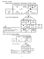
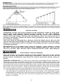
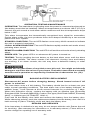
Visit Us on the Web! www.SmokeAlarms.com
MODEL USI-2430
HEAT ALARM
120 VAC WITH
9V BATTERY BACKUP
OWNER'S MANUAL
PLEASE READ AND SAVE!
Installer: Please leave this manual with the product.
WHAT YOU SHOULD KNOW ABOUT HEAT ALARMS
FEATURES
Heat alarms are not life safety devices and are not designed to
detect smoke or fire. They are intended to detect temperatures of
135oF or more and to provide an additional source of information
that is supplemental to smoke alarms to increase the probability that
an early warning will be provided to increase chances of life and
property safety.
•
This heat alarm is powered by 120 VAC and a 9 Volt battery backup source. AC/
DC heat alarms offer added protection in the event of a power failure or a drained
battery.
•
This alarm may be interconnected with a total of not more than 24 interconnected
devices, i.e., as many as 12 other USI ELECTRIC or UNIVERSAL model smoke
alarms or combination smoke and carbon monoxide (CO) or smoke and carbon
monoxide / natural gas alarms; 5 other initiating alarms which may be a combination
of USI ELECTRIC or UNIVERSAL CO Alarms and Heat Alarms; and six other noninitiating devices such as USI ELECTRIC Relay Modules
•
This heat alarm will not attach to the mounting ring if a battery is not in the battery
chamber.
•
This heat alarm will sound a short beep about once a minute if the battery is weak
or improperly connected.
•
The green LED indicates that the heat alarm is receiving AC power and is working
under normal operation.
•
A loud 85 decibels at 10 feet alarm horn will sound to alert you of an emergency.
•
The test button checks heat alarm operation.
SPECIFICATIONS
Model Number
USI-2430
Electrical Rating
120 VAC, 60 Hz, 50 mA maximum, 9 Volt
battery backup
Interconnect
24 units maximum
Interconnect with
Up to 5 USI heat alarms or CO alarms and
up to 12 USI smoke alarms and 6 other
non-initiating devices (Relay Modules)
UL Temperature Rating
135oF (57oC) fixed temperature
UL Maximum Ambient Temperature
at Unit
100oF (38oC)
Operating Temperature
-10oF to 158oF (-23oC to 70oC)
UL Recommended Coverage
2500 square feet (see Note A:)
UL Recommended Spacing
50 feet
Maximum Distance from Wall
25 feet (see Note B:)
NOTE A:
Maximum alarm coverage has been determined by UL to provide detection time equal
to sprinkler devices spaced at 10 foot intervals (100 square foot area) on a smooth
ceiling 15 ft. x 8 in. high. Higher ceilings can adversely affect detection time. In some
instances, earlier detection may be obtained by reducing the spacing between detectors.
See the latest edition of NFPA 72, National Fire Alarm Code.
NOTE B:
Maximum distance is from any wall partition or ceiling projection extending down more
than 12 in.
IMPORTANT SAFETY INFORMATION
PLEASE READ AND SAVE THESE INSTRUCTIONS
This heat alarm requires constant 120 Volt AC power AND a working 9 Volt
battery to operate properly. This heat alarm WILL NOT work if AC power is
not connected or has failed or has been interrupted for any reason AND the
batteries removed, drained or improperly connected. DO NOT use any other
kind of battery except as specified in this manual. DO NOT connect this
heat alarm to any other type of smoke alarm or heat alarm or auxiliary
device, except those listed in this manual.
• This heat alarm should be installed only by a licensed, qualified electrician. Observe and follow
all local and national electrical building codes for installation.
• Heat alarms should be interconnected with smoke alarms in order to provide early warning of
heat, smoke or fire. In addition, smoke alarms should be installed in every bedroom and on
every level of the home.
• Heat alarms interconnected with smoke alarms may not alert every household member every
time. The alarm horn of the heat alarm and smoke alarm is loud in order to alert individuals of
a potential danger. However, there may be limiting circumstances where a household member
may not hear the alarm (i.e. outdoor or indoor noise, sound sleepers, drug or alcohol use, the
hearing impaired, etc.). If you suspect that your heat alarm or smoke alarm may not alert a
household member, install and maintain specialty smoke alarms. Household members must
hear the alarm's warning sound and quickly respond to it to reduce the risk of damage, injury
or death that may result from fire. This heat alarm cannot be interconnected with specialty
smoke alarms unless specified in this manual.
• Heat alarms should be used to provide an added source of information and supplement smoke
alarm installation. Some fires are slow, smoldering, low heat-producing or are in a different
room than the heat alarm, or the heat from the fire may bypass the alarm. This heat alarm will
not always detect this type of fire.
• The push-to-test button accurately tests all heat alarm functions. For temperatures that are
below minus 10oF, use a handheld hair dryer and blow hot air (one foot away) into the heat alarm
to test. DO NOT use any other test method. Test heat alarm weekly to ensure proper operation.
• This heat alarm is designed to be used inside a single family household only. In multi-family
buildings, each individual living unit should have its own heat alarm. Do not install in nonresidential buildings or places which house many people like hotels, motels, dormitories,
hospitals, nursing homes or group homes of any kind. This heat alarm is not a substitute for
a complete alarm system.
• Interconnected heat alarms and smoke alarms offer maximum protection. The National Fire
Protection Agency (NFPA) recommends interconnecting heat alarms and smoke alarms so
that when one unit senses heat, smoke or fire and sounds its alarm, all others will sound as
well. Do not interconnect heat alarms or smoke alarms from one individual family living unit to
another. Do not connect this heat alarm to any other type of alarm (except those stated in this
manual) or auxiliary device.
• This heat alarm can only sound its alarm when it detects temperatures of 135oF (57oC) or
greater. Heat alarms do not sense smoke, fire or gas. In some fires, hazardous levels of toxic
chemicals and smoke can build up before a heat alarm will operate. Temperatures may not
reach 135o F (57oC) to activate the heat alarm quickly enough to ensure safe escape.
• Heat alarms have limitations. This heat alarm is not foolproof and is not warranted to protect lives or
property. Heat alarms are not a substitute for insurance. Homeowners and renters should insure their
lives and property. In addition, it is possible for the heat alarm to fail at any time.
HEAT ALARM PLACEMENT
Heat alarms give an audible warning when the temperature at the alarm reaches 135oF (57oC) or greater.
Heat alarms are ideal for kitchens, garages, basements, boiler rooms, attics and other areas where there
are normally high levels of fumes, smoke or dust which are also areas where smoke alarms should not
be installed due to risk of false nuisance alarms.
-2-
EXISTING HOMES
NEW CONSTRUCTION HOMES
-3-
HEAT ALARM LOCATIONS
Install a heat alarm as close to the center of the ceiling as possible. If the center is not
practical, mount the heat alarm no closer than 4 inches from a wall or corner.
If the ceiling is not practical or the mounting surface becomes considerably warmer
or cooler than the room, such as a poorly insulated ceiling, below an unfinished attic
or an exterior wall (if local codes allow), install the heat alarm on inside walls with the
top of the alarm between 4 and 12 inches from the ceiling/wall intersections.
Install heat alarms on peaked cathedral or gabled ceilings 3 feet from the highest point
(measured horizontally).
In rooms with open joists or beams, all ceiling mounted heat alarms should be located
on the bottom of such joists or beams and not up in joist channels.
Heat alarms installed on an open-joisted ceiling shall have their smooth ceiling spacing
reduced to no more than half of the listed spacing when measured at right angles to
a solid joist.
DO NOT INSTALL HEAT ALARMS
•
In areas with high humidity, like bathrooms/shower rooms or areas near
dishwashers or washing machines. Install at least 10 feet (3m) away from these
areas if possible.
•
Near air returns or heating and cooling supply vents, fans, decorative objects,
window molding, etc. that may prevent heat from entering the unit thus interrupting
its alarms.
•
In an area where temperature may fall below -10oF (-23oC) or rise above 100oF
(38oC).
•
Near fluorescent lights. Electrical "noise" and flickering may affect the alarm's
operation.
MOBILE HOME INSTALLATION
For mobile homes built after 1978, install heat alarms as directed above. For mobile
homes built before 1978, install heat alarms on inside wall between 4 and 12 inches
from the ceiling. Older mobile homes have little or no insulation in the ceiling which
may affect the heat alarm's ability to detect heat properly. This is especially important
if the ceiling is unusually hot or cold.
-4-
INSTALLATION
Installation of this unit must conform to the electrical codes in your area;
Article 760 of the National Electrical Code, NFPA 72, 101; SBC (SBCCI);
UBC (ICBO); NBC (BOCA): OTFDC (CABO), and any other local or building
codes that may apply. Wiring and installation must be performed by a
licensed electrician. Failure to follow these guidelines may result in injury
or property damage.
This unit must be powered by a 24-hour, 120V AC 60Hz circuit. Be sure the
circuit cannot be turned off by a switch, dimmer or ground fault circuit interrupter.
Failure to connect this unit to a 24-hour circuit may prevent it from providing
constant protection.
iMPORTANT: Do not subject this alarm to megger, high voltage or highpot tests. Remove the heat alarm(s) before high-potting tests occur on the
circuit or system. (Ref. Section 550-17 National Electric Code, 2002 Edition).
ELECTRICAL SHOCK HAZARD
Turn off power to the area where you will install this unit at the circuit
breaker or fuse box before beginning installation. Failure to turn off the
power before installation may result in serious electrical shock, injury or
death.
TAMPER LOCKING PIN: To make your heat alarm somewhat tamper resistant, a
locking pin has been provided. Using this pin will deter children and others from
removing the alarm from the mounting ring. To use the pin, insert it into the hole in the
side of the alarm after it has been installed on the mounting ring. Note that the tamper
pin will have to be removed in order to change the battery, which can be done easily
with a pair of long nose pliers. Using the long nose pliers, pull the pin out of the hole.
It is now possible to remove the heat alarm from the mounting ring.
1. Turn the heat alarm counterclockwise to remove it from the mounting ring. NOTE:
The heat alarm is sealed and the cover is not removable. Your heat alarm is also
equipped with a safety device which prevents mounting unless a battery is installed.
If your heat alarm will not lock onto the mounting ring, check to make sure a
battery is installed.
-5-
2. Wiring Instructions:
a. The appropriate power supply is 120 Volt single phase power supplied from
a non-switchable circuit NOT protected by a ground fault circuit interrupter.
b. Turn off main power to the circuit before wiring the heat alarm.
c. There are three pigtail leads (black, white and yellow) coming from the AC
QUICK CONNECTOR. The proper wire connection is as follows:
WIRES FROM QUICK CONNECTOR
BLACK
WHITE
YELLOW
CONNECT TO
"HOT" side of AC line
"NEUTRAL" side of AC line
Interconnect wires of other units
For units that are used as single heat alarms, do not connect the yellow wire to
anything. Insulate this wire (tape it) in place to make certain the yellow wire
cannot contact any metal parts.
INTERCONNECTION & COMPATIBILITY: Interconnected alarms can provide
earlier warning of fire than stand-alone alarms, especially if a fire starts in
a remote area of the dwelling. When alarms are interconnected, all alarms
will sound when one alarm first goes into alarm. This alarm may be
interconnected with a total of not more than 24 interconnected devices, i.e.,
as many as 11 other USI ELECTRIC or UNIVERSAL model smoke alarms or
combination smoke and carbon monoxide (CO) or smoke and carbon
monoxide / natural gas alarms; 6 other initiating alarms which may be a
combination of USI ELECTRIC or UNIVERSAL CO Alarms and Heat Alarms;
and six other non-initiating devices such as USI ELECTRIC Relay Modules.
This alarm can be interconnected with the following models: 2995, 5304,
MI100, MI106, MDS211, MDS201, 2985, 5303, MI200, MI210, MDS101, MDS107,
3885, 3895, MP118, MP117, 3303, 3304, MP202, MP212, MDSCN111, MDSCN103,
MICN109, MICN102, MCN105, MCN108, SS-785, SS-790, SS-795, SS-2795, SS2790, SS-2785, SS-2895, HD-130, USI-1103, USI-1203, USI-1204, USI-1208 (Part
#USI-1209), USI-1213, USI-2430, USI-3204, USI-5204, USI-5208, USI-5213, USI7385, USI-7390, USI-7485, USI-7490, CD-9385, CD-9390, CD-9485, CD-9490, CD9795, USI-7795 AND USI-960, RM-100 Relay.
When any one of these interconnected models goes into alarm, it will trigger
the corresponding alarm within the interconnected system with respect to
their sensing capabilities. Natural gas detection is only present in models
MDSCN111, MSDCN103, MICN109, MICN102, MCN108 and MCN105; therefore,
a natural gas alarm will NOT trigger the alarm of non-natural gas sensing
models within an interconnected system.
Interconnected CO alarms or CO alarm circuit of combination smoke and
CO and Natural Gas alarms will only respond if a CO alarm / event initiates
the alarm. All other alarms remain silent.
-6-
Interconnected combination Natural Gas Alarms will only respond if a
natural gas event initiated the alarm. All other alarms remain silent.
Interconnected smoke alarms, heat alarms and relay modules will only
respond if a smoke alarm / event or heat alarm / event initiates the alarm.
All CO and Natural Gas alarms remain silent.
Note that alarms without battery backup will not respond during an AC power
failure.
NOTE: Relay Modules/USI-960 will not respond if a CO or Natural Gas
alarm / event initiates the alarm.
The yellow wire is used only for multiple station operation with USI Models
only. Connecting this yellow wire to any other circuits may result in damage.
When heat alarms are interconnected, all units must be powered from a
single AC branch circuit. If local codes do not permit be sure the neutral
wire is common to both phases. The maximum wire run distance between
the first and last heat alarm in an interconnected system is 1,000 feet.
NOTE: Use standard household wire (18 gauge or larger, rated at least 300V,
as required by local codes) available at all electrical supply/hardware
stores.
The wiring to be used shall be in accordance with the provisions of Articles
210 and 300.3(B) of the National Electrical Code, ANSI/NFPA 70. In addition,
the resistance of the interconnecting wiring shall be a maximum of 10
Ohms.
Early warning fire detection is best achieved by the installation of fire
detection equipment in all rooms and areas of the household as follows: A
smoke alarm installed in each separate sleeping area (in the vicinity of,
but outside of, the bedrooms) and heat or smoke alarms in living rooms,
dining rooms, kitchens, hallways, attics, furnace rooms, closets, utility
storage rooms, basements and attached garages. Test the heat or smoke
alarm weekly to assure proper operation.
3. Attach the mounting ring to the electrical junction box.
4. To activate 9 volt battery and heat alarm, pull and remove the thin colored plastic
tab at battery door hinge. Discard plastic tab.
5. Plug the AC QUICK CONNECTORS together. Push and turn the heat alarm clockwise
onto the mounting ring.
6. See "TAMPER LOCKING PIN."
7. Turn on AC power and check the LED's for proper operation. The green LED lights to
indicate AC power. The red LED will flash every 40-60 seconds to indicate proper
operation.
-7-
OPERATION, TESTING & MAINTENANCE
OPERATION: The heat alarm is operating once the power is connected and turned on
(the battery must also be installed). When air temperature at or above 135oF (57oC) is
sensed, the unit sounds a loud alarm which continues until the air temperature drops
below 135oF.
This alarm incorporates the internationally recognized horn signal for evacuation.
During alarm mode, the horn produces three short beeps followed by a two second
pause and then repeats.
STANDBY CONDITION: The red LED flashes once every 40-60 seconds to indicate
the unit is properly functioning.
LOCAL ALARM CONDITION: The red LED flashes rapidly and the unit emits a loud,
pulsating alarm sound.
REMOTE ALARM CONDITION: The red LED is off and the unit emits a loud, pulsating
alarm.
GREEN LED: The green LED is on whenever AC power is turned on.
TESTING: Test by pushing the test button on the heat alarm cover until the alarm
sounds, then release. The alarm sounds if all electronic circuitry, horn and battery
are working. If no alarm sounds, the unit may have a defective battery or other
failure.
NEVER use an open flame of any kind to test this unit. You might accidentally
damage or set fire to the unit or to your home. The built-in test switch accurately
tests the unit's operation as required by Underwriters Laboratories Inc. (UL).
BACKUP BATTERY REPLACEMENT
Disconnect AC power before changing battery. Shock hazard exists if AC
power is miswired.
The heat alarm uses a 9 Volt battery. The battery should last for at least one year
under normal operating conditions. The heat alarm has a low battery indicator, an
audible "beep." It will operate at 30-40 second intervals for a minimum of 7 days.
When this indication occurs, replace the battery with an Alkaline type (Eveready
Energizer #522, Duracell #MN1604), Carbon-Zinc type (Gold Peak #1604S, Eveready
#216), or Lithium type (ULTRALIFE U9VL-J).
Push and lift the battery door latch and remove the battery from the battery door.
While observing polarity, push the replacement battery into the battery door until it is
held securely in place. Carefully close and latch the battery door.
REPAIRS AND SERVICES
If the heat alarm is defective in any way, do not tamper with the unit. Return the unit
for servicing. (See warranty for instructions or in-warranty returns.) There will be a
service charge for repairing out of warranty units.
-8-
DEVELOP AND PRACTICE A PLAN OF ESCAPE
BASICS OF ESCAPE PLAN
o Make a floor plan indicating all doors and windows and at least two escape routes
from each room. Second story windows may need a rope or chain ladder.
o Have a family meeting and discuss your escape plan, showing everyone what to
do in case of fire.
o Determine a place outside your home where all of you can meet if a fire occurs.
o Familiarize everyone with the sound of the heat alarm and train them to leave your home
when they hear the sound.
o Identify children's bedrooms with red stickers placed in the upper left corner of the
windows. They are available from your local fire department.
o Practice a fire drill at least every six months. Practice allows you to test your plan
before an emergency. You may not be able to reach your children. It is important
they know what to do!
WHAT TO DO WHEN THE ALARM SOUNDS
o Leave immediately by your plan of escape. Every second counts, so don't waste
time getting dressed or picking up valuables.
o In leaving, don't open any inside door without first feeling its surface. If hot, or if
you see smoke seeping through cracks, don't open that door! Instead, use
your alternate exit. If inside door is cool, place your shoulder against it, open it
slightly and be ready to slam it shut if heat and smoke rush in.
o Stay close to the floor if air is smoky. Breathe shallowly through a cloth, wet if
possible.
o Once outside, go to your selected meeting place and make sure everyone is there.
o Call the fire department from your neighbor's home – not from yours!
o Don't return to your home until fire officials say that it is all right to do so.
NATIONAL FIRE PROTECTION ASSOCIATION REQUIRED PROTECTION
For your information, the National Fire Protection Association's Standard 72, reads as follows:
“11.5.1 One- and Two-Family Dwelling Units. 11.5.1.1 Smoke Detection. Where required
by applicable laws, codes, or standards for the specified occupancy, approved singleand multiple-station smoke alarms shall be installed as follows: (1) In all sleeping
rooms. Exception: Smoke alarms shall not be required in sleeping rooms in existing
one- and two-family dwelling units. (2) Outside of each separate sleeping area, in
immediate vicinity of the sleeping rooms. (3) On each level of the dwelling unit,
including basements. Exception: In existing one- and two-family dwelling units, approved
smoke alarms powered by batteries are permitted.
“A.11.8.3 Are More Smoke Detectors Desirable? The required number of smoke detectors
might not provide reliable early warning protection for those areas separated by a door
from the areas protected by the required smoke detectors. For this reason, it is
recommended that the householder consider the use of additional smoke detectors for
those areas for increased protection. The additional areas include the basement,
bedrooms, dining room, furnace room, utility room, and hallways not protected by the
required smoke detectors. The installation of smoke detectors in kitchens, attics
(finished or unfinished), or garages is not normally recommended, as these locations
occasionally experience conditions that can result in improper operation.”
The equipment should be installed using wiring methods in accordance with the National Fire
Protection Association’s Standard 72, Chapter 11. (National Fire Protection Association, Batterymarch
Park, Quincy, MA 02269).
THIS PRODUCT MEETS ALL THE REQUIREMENTS OF
UL STANDARDS FOR SAFETY, UL217 AND UL539.
-9-
PRODUCT FIVE-YEAR LIMITED WARRANTY
MODEL USI-2430
USI ELECTRIC, INC. / UNIVERSAL SECURITY INSTRUMENTS, INC. (“USI”) warrants
your product to be free from defects in material and workmanship for a period of five (5)
years from the date of purchase. This warranty shall not apply to any batteries used in the
product or to any damage which may be caused by such batteries. This warranty applies only
to the original consumer purchaser and only to products used in normal residential use and
service. If this product is found to be defective, USI’s only obligation, and your exclusive
remedy, is the repair or replacement of the product, at USI’s discretion, provided that the
product has not been damaged through misuse, abuse, accident, modifications, alteration,
neglect or mishandling. This Warranty shall not apply to any product which is found to have
been improperly installed, set-up, or used in any way not in accordance with the instructions
supplied with the product.
ALARM RETURNS
For replacement of this alarm under the terms of this Warranty, contact Customer Service at
1-800-390-4321, Ext. 238, for current postage and handling fees. USI DOES NOT WARRANT
AND SPECIFICALLY DISCLAIMS ANY WARRANTY, WHETHER EXPRESS OR IMPLIED, OF
FITNESS FOR A PARTICULAR PURPOSE, OTHER THAN THE WARRANTY CONTAINED
HEREIN. NO IMPLIED WARRANTY ON THIS PRODUCT, CREATED BY STATE LAW, SHALL
EXTEND BEYOND THE TERM OF THIS WARRANTY UNLESS SUCH LAW OTHERWISE
PROVIDES. USI SPECIFICALLY DISCLAIMS ANY LIABILITY AND SHALL NOT BE LIABLE
FOR ANY CONSEQUENTIAL OR INCIDENTAL LOSS OR DAMAGE, INCLUDING, BUT NOT
LIMITED TO, DAMAGES TO ANY EQUIPMENT WITH WHICH THIS PRODUCT IS USED. Some
states do not allow the exclusion or limitation of incidental or consequential damages, so the
above limitations or exclusions may not apply to you. No agent, representative, dealer, or
employee of the company has the authority to increase or alter the obligations or terms of this
Warranty. This Warranty gives you specific legal rights and you may also have other rights
which vary from state to state. This Warranty is only valid for merchandise purchased from
outlets in the United States and Canada. This warranty expires upon product end-of-service life
signal.
LITHIUM BATTERY LIMITED WARRANTY
The Ultralife battery model U9VL-J is warranted by Ultralife Corporation in this alarm ONLY and
are not warranted in any other device. Submit your warranty claim through the Ultralife website
www.ultralifecorp.com or call 800-332-5000.
Visit Us on the Web! www.UsiElectric.com
11407 Cronhill Drive, Suite A
Owings Mills, Maryland 21117 USA
288-3256-01
©2000 UNIVERSAL SECURITY INSTRUMENTS, INC., Rev. 10/2012
Printed in China