1
LORENZ MESSTECHNIK GmbH
Obere Schloßstr.131
73553 Alfdorf
07172 / 93730-0
Fax 07172 /93730-22
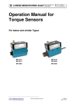
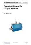
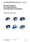
Operation Manual
for Torque Sensors
For Type MR-12 and similar
E-Mail: [email protected]
Internet: www.lorenz-sensors.com
Technical changes reserved
090268.doc
Page 1 of 11
LORENZ MESSTECHNIK GmbH
Obere Schloßstr.131
73553 Alfdorf
07172 / 93730-0
Fax 07172 /93730-22
Imprint
Manufacturer, Place Lorenz Messtechnik GmbH, D-73553 Alfdorf.
Valid for...
Torque sensor type MR-12
Copyright
© 2006 Lorenz Messtechnik GmbH, Alfdorf.
Reprint Interdiction Reprints, even in extracts, only with written authority.
Modification
Technical changes reserved.
References in this Text
1.6 Warning Notes; Page 5
Attention must be paid to the accident prevention regulations of the trade associations.
Coverings and casings are necessary before operating the sensor. This is also valid for
commissioning, maintenance and trouble shooting.
Duties of the coverings and casings are:
⇒ Protection from detaching parts
⇒ Protection from contusion and shear
⇒ Prevention from reaching rotating parts
⇒ Prevention from being tangled up and/or getting caught by parts
Coverings may
⇒ Not grind
⇒ Not rotate
Coverings are also necessary outside of operating and motion travel areas of persons.
These demands can be modified if other sufficient safety devices are available. During
operation, the safety precautions must be operative. By vibrations, damages can occur at
the device.
4 Mechanical Assembly; Page 7
Before the assembly, connection elements must be cleaned with dissolver (e.g. acetone),
no foreign particles may adhere to them
Caution: During the assembly inadmissibly large forces may not act on the sensor.
During the assembly, the sensor must be supported to protect if from falling down.
6.1 Engaging; Page 9
Warming-up period of the sensor is approx. 5 min.
6.4.2 Natural Resonances; Page 9
An operation of the device in natural resonance can lead to permanent damages.
E-Mail: [email protected]
Internet: www.lorenz-sensors.com
Technical changes reserved
090268.doc
Page 2 of 11
LORENZ MESSTECHNIK GmbH
Obere Schloßstr.131
73553 Alfdorf
07172 / 93730-0
Fax 07172 /93730-22
Contents
1
Read First.............................................................................................................................................. 4
1.1
Safety and Caution Symbols.......................................................................................................... 4
1.2
Intended Use.................................................................................................................................. 4
1.3
Dangers.......................................................................................................................................... 4
1.3.1
Neglecting of Safety Notes ..................................................................................................... 4
1.3.2
Remaining Dangers ................................................................................................................ 4
1.4
Reconstructions and Modifications ................................................................................................ 4
1.5
Personnel ....................................................................................................................................... 4
1.6
Warning Notes ............................................................................................................................... 5
2 Term Definitions .................................................................................................................................... 5
2.1
Terms ............................................................................................................................................. 5
3 Product Description ............................................................................................................................... 6
3.1
Mechanical Setup........................................................................................................................... 6
3.2
Electrical Setup .............................................................................................................................. 6
4 Mechanical Assembly............................................................................................................................ 7
5 Electrical Connection............................................................................................................................. 8
5.1
Pin Connection............................................................................................................................... 8
5.2
Calibration Control ......................................................................................................................... 8
5.3
Cable.............................................................................................................................................. 8
5.4
Shielding Connection ..................................................................................................................... 8
5.5
Running of Measuring Cables........................................................................................................ 8
5.6
Angle (Option) ................................................................................................................................ 9
6 Measuring.............................................................................................................................................. 9
6.1
Engaging ........................................................................................................................................ 9
6.2
Direction of Torque......................................................................................................................... 9
6.3
Static / Quasi-Static Torques ......................................................................................................... 9
6.4
Dynamic Torques ........................................................................................................................... 9
6.4.1
General ................................................................................................................................... 9
6.4.2
Natural Resonances ............................................................................................................... 9
6.5
Speed Limits .................................................................................................................................. 9
6.6
Disturbance Variables.................................................................................................................. 10
7 Maintenance........................................................................................................................................ 10
7.1
Maintenance Schedule ................................................................................................................ 10
7.2
Trouble Shooting.......................................................................................................................... 10
8 Decommission..................................................................................................................................... 11
9 Transportation and Storage ................................................................................................................ 11
9.1
Transportation .............................................................................................................................. 11
9.2
Storage......................................................................................................................................... 11
10
Disposal ........................................................................................................................................... 11
11
Calibration........................................................................................................................................ 11
11.1
Proprietary Calibration.............................................................................................................. 11
11.2
DKD-Calibration........................................................................................................................ 11
11.3
Re-Calibration........................................................................................................................... 11
12
Data Sheet....................................................................................................................................... 11
13
Literature.......................................................................................................................................... 11
E-Mail: [email protected]
Internet: www.lorenz-sensors.com
Technical changes reserved
090268.doc
Page 3 of 11
LORENZ MESSTECHNIK GmbH
1
Read First
1.1
Safety and Caution Symbols
Obere Schloßstr.131
73553 Alfdorf
07172 / 93730-0
Fax 07172 /93730-22
Caution:
Injury Risk for Persons
Damage of the Device is possible.
Note:
Important points to be considered.
1.2
Intended Use
Torque sensors are intended for the measurement of torques. This measurand is further suitable for
control tasks. The valid safety regulations should be absolutely respected. The torque sensors are not
safety components in the sense of the intended use. The sensors need to be transported and stored
appropriately. The assembly, commissioning and disassembling must take place professionally.
1.3
Dangers
The torque sensor is fail-safe and corresponds to the state of technology.
1.3.1 Neglecting of Safety Notes
At inappropriate use, remaining dangers can emerge (e.g. by untrained personnel). The operation manual
must be read and understood by each person entrusted with the assembly, maintenance, repair,
operation and disassembly of the torque sensor.
1.3.2 Remaining Dangers
The plant designer, the supplier, as well as the operator must plan, realize and take responsibility for
safety-related interests for the sensor. Remaining dangers must be minimized. Remaining dangers of the
torque measurement technique must be pointed out.
Human mistakes must be considered. The construction of the plant must be suitable for the avoidance of
dangers. A danger-analysis for the plant must be carried out.
1.4
Reconstructions and Modifications
Each modification of the sensors without our written approval excludes liability on our part.
1.5
Personnel
The installation, assembly, commissioning, operation and the disassembly must be carried out by
qualified personnel only. The personnel must have the knowledge and make use of the legal regulations
and safety instructions.
E-Mail: [email protected]
Internet: www.lorenz-sensors.com
Technical changes reserved
090268.doc
Page 4 of 11
LORENZ MESSTECHNIK GmbH
1.6
Obere Schloßstr.131
73553 Alfdorf
07172 / 93730-0
Fax 07172 /93730-22
Warning Notes
Attention must be paid to the accident prevention regulations of the trade associations.
Coverings and casings are necessary before operating the sensor. This is also valid for
commissioning, maintenance and trouble shooting.
Duties of the coverings and casings are:
⇒ Protection from detaching parts
⇒ Protection from contusion and shear
⇒ Prevention from reaching rotating parts
⇒ Prevention from being tangled up and/or getting caught by parts
Coverings may
⇒ Not grind
⇒ Not rotate
Coverings are also necessary outside of operating and motion travel areas of persons.
These demands can be modified if other sufficient safety devices are available. During
operation, the safety precautions must be operative. By vibrations, damages can occur
at the device.
2
Term Definitions
2.1
Terms
Measuring Side:
Mechanical connection of the torque sensor in which the torque to be measured is applied. Usually this
side has the smallest moment of inertia.
Drive Side:
Mechanical connection of the torque sensor on the opposite side of the measuring side, usually with the
largest moment of inertia. At static torque sensors the housing is fastened on this side.
Low Torque Resistance Side:
The shaft of the arrangement (drive, load) which can be turned considerably smaller with torque than the
nominal torque of the torque sensor M << Mnenn .
E-Mail: [email protected]
Internet: www.lorenz-sensors.com
Technical changes reserved
090268.doc
Page 5 of 11
LORENZ MESSTECHNIK GmbH
3
Obere Schloßstr.131
73553 Alfdorf
07172 / 93730-0
Fax 07172 /93730-22
Product Description
The sensor measures static and dynamic torques. The mounting position of the torque sensor is
horizontally or vertically.
3.1
Mechanical Setup
The sensors consist of a torsion shaft. The connection is carried out by a belt pulley and a shaft with
feather key. The torsion shaft is applied with strain gauges. For the signal transmission and/or the supply
of the strain gauge full bridges, a rotating transformer, according to the principle of a transformer, is
arranged in the sensor. For supply and measuring signal conditioning, electronics are integrated in the
stator and the rotor.
Belt pulley
SG
Option
Angle Sensor
Connector
Stator
Shaft with feather key
Rotating transformer
Torsion shaft
Support bearings
3.2
Electrical Setup
The supply of the rotor electronics occurs by an alternating voltage, generated in the stator, which
transfers to the rotor through a rotating transformer. There, it is rectified and stabilized. With this supply,
the strain gauge bridge is fed.
For the electrical calibration control of the sensor, a control signal is up-modulated to the supply by the µprocessor in the stator and transferred to the rotor. There, it is filtered and evaluated by the µPC, which
also activates the internal switch for the detuning of the strain gauge bridge.
The measuring signal of the strain gauge bridge is conditioned in an amplifier and then converted into a
digital signal, which will be transferred to the stator by another rotating transformer. Compared to the
analog signal, the measuring signal in digital form is much more disturbance-free. The remaining distance
of the measuring signal within the sensor occurs in digital form, completely. Thus, the measuring system
achieves a high reliability of operation.
This signal is further conditioned in the stator, comes into a µ-processor, then - depending upon sensor
type - it is converted to a voltage signal, digital signal or to current and will then reach the output of the
sensor and can be directly measured at the connector.
E-Mail: [email protected]
Internet: www.lorenz-sensors.com
Technical changes reserved
090268.doc
Page 6 of 11
LORENZ MESSTECHNIK GmbH
Obere Schloßstr.131
73553 Alfdorf
07172 / 93730-0
Fax 07172 /93730-22
Rotating Transformer
Supply
Voltage
SG
AC
Supply and
Control Signal
Cycle and
Control Signal
Calibration
Control
DC
Oscillator
4 MHz
DC /DC
Filter for
Control Signal
µ - Processor
Amplifier
Rotating Transformer
Signal Adaption
Analog or Digital
Signal
Output
Signal
Conditioning
µ-Processor
Serial Data Transmission
A/D-Converter
± 11 bit
± 15 bit
A
Rotation
Angle Output
(Option )
B
Signal
Conditioning
Rotation Angle (Option)
Stator
Rotor
Block diagram for serial signal transmission
4
Mechanical Assembly
Before the assembly, connection elements must be cleaned with dissolver (e.g. acetone), no
foreign particles may adhere to them
Caution: During the assembly inadmissibly large forces may not act on the sensor.
During the assembly, the sensor must be supported to protect if from falling down.
Belt pulley
Cable connection
Stator
Fixing screw
Drive shaft
Assembly Sequence:
• Mount belt pulley on torque sensor and secure it with screws (e.g. use adhesive for the screw
locking).
• Shift torque sensor onto drive shaft
• Secure torque sensor axially with lock screw. E.g. secure screw with lock screw adhesive.
Apply twist lock for stator. (see data sheet for mounting possibility), the cable connection may not be
used as a twist lock. Use an elastic element or a catch.
E-Mail: [email protected]
Internet: www.lorenz-sensors.com
Technical changes reserved
090268.doc
Page 7 of 11
LORENZ MESSTECHNIK GmbH
5
Electrical Connection
5.1
Pin Connection
Obere Schloßstr.131
73553 Alfdorf
07172 / 93730-0
Fax 07172 /93730-22
Also see test certificate.
12pin
A
B
C
D
E
F
G
H
J
K
L
M
Analog
NC
Option angle B
Signal
Signal GND
Excitation GND
Excitation +
Option angle A
NC
NC
Calibration
Control
NC
Housing
TTL
±5 V / (±10 V)
0V
0V
12 ... 28 VDC
TTL
L<2,0 V;
H>3,5 V
View: socket on soldering side
5.2
Calibration Control
Only use calibration control in unloaded condition of the torque sensor.
Applying of voltage +3,5 V up to +28 V will enable the
calibration control.
Voltage below 2,8 V will disable the calibration control.
E
K
Excitation (GND)
Calibration control
Exc. GND
Ukal
+
3,5 VDC < Ukal < 28 VDC
Cal. control
5.3
Cable
Only use a shielded cable with preferably small capacity. We recommend measuring cables from our
product range. They have been tested in combination with our sensors and meet the metrological
requirements.
5.4
Shielding Connection
In combination with the sensor and the external electronics, the shield forms a Faraday Cage. By this,
electro-magnetic disturbances do not have any influence on the measurement signal.
5.5
Running of Measuring Cables
Do not run measuring cables together with control or heavy-current cables. Always assure that a large
distance is kept to engines, transformers and contactors, because their stray fields can lead to
interferences of the measuring signals.
If troubles occur through the measuring cable, we recommend to run the cable in a grounded steel
conduit.
E-Mail: [email protected]
Internet: www.lorenz-sensors.com
Technical changes reserved
090268.doc
Page 8 of 11
LORENZ MESSTECHNIK GmbH
5.6
Obere Schloßstr.131
73553 Alfdorf
07172 / 93730-0
Fax 07172 /93730-22
Angle (Option)
At angle or speed measurement, the pulses / revolutions
are acquired. By a second transmitter trace, displaced by
90° and flank evaluation, the pulses / revolutions can be
quadrupled. The trace, displaced by 90°, can also be
used for the rotational direction detection.
See corresponding data sheet for the output levels.
Supply for angle sensor
Stabilized supply voltage
5 V ±25 mV
Current consumption max.
20 mA
6
Measuring
6.1
Engaging
The warming-up period of the torque sensor is approx. 5 min. Afterwards the measurement can be
started.
The warming-up period of the torque sensor is approx. 5 min.
6.2
Direction of Torque
Torque means clockwise or clockwise torque if the torque acts clockwise when facing the shaft end. In
this case a positive electrical signal is obtained at the output.
Torque sensors by Lorenz Messtechnik GmbH can measure both, clockwise and counter-clockwise
direction.
6.3
Static / Quasi-Static Torques
Static and/or quasi-static torque is a slowly changing torque.
The calibration of the sensors occurs statically on a calibration device.
The applied torque may accept any value up to the nominal torque.
6.4
Dynamic Torques
6.4.1 General
The static calibration procedure of torque sensors is also valid for dynamic applications.
Note: The frequency of torques must be smaller than the natural frequency of the mechanical
measurement setup.
The band width of alternating torque must be limited to 70 % of the nominal torque.
6.4.2 Natural Resonances
c
Estimate of the mechanical natural frequencies:
f0 =
⎛1
1
1 ⎞
⋅ c ⋅ ⎜⎜ + ⎟⎟
2 ⋅π
⎝ J1 J 2 ⎠
f0
J1, J2
c
= Natural Frequency in Hz
= Moment of Inertia in kg*m²
= Torsional Rigidity in Nm/rad
J2
J1
Further methods for the calculation of natural resonances are corresponding purchasable programs or
books (e.g. Holzer-Procedure, Dubbel, Taschenbuch für den Maschinenbau, Springer Verlag)
An operation of the device in natural resonance can lead to permanent damages.
6.5
Speed Limits
The maximum speed indicated in the data sheet may not be exceeded in any operating state..
E-Mail: [email protected]
Internet: www.lorenz-sensors.com
Technical changes reserved
090268.doc
Page 9 of 11
LORENZ MESSTECHNIK GmbH
6.6
Obere Schloßstr.131
73553 Alfdorf
07172 / 93730-0
Fax 07172 /93730-22
Disturbance Variables
By disturbances, measured value falsifications can occur by
• Vibrations,
• Temperature gradients,
• Temperature changes,
• Arising disturbance variables during operation, e.g. imbalance,
• Electrical disturbances,
• Magnetic disturbances,
• EMC (electromagnetic disturbances),
Therefore avoid these disturbance variables by decoupling of vibrations, covers, etc.
7
Maintenance
7.1
Maintenance Schedule
Action
Control of cables and connectors
Calibration
Control of fixation (flanges, shafts)
Have bearings exchanged by Lorenz
Messtechnik GmbH
7.2
Frequency
Date
1x p.a.
< 26 months
1x p.a.
20000 hrs
operating time
Date
Date
Trouble Shooting
This chart is used for searching for the most frequent errors and their elimination
Problem
Possible Cause
Trouble Shooting
No signal
No sensor excitation
• Outside of permissible range
• Connect excitation
• Cable defect
• No mains supply
Signal output connected wrong
• Connect output correctly
• Evaluation electronics defect
Sensor does not react to torque
Shaft not clamped
• Clamp correctly
No power supply
• Outside of permissible range
• Connect supply
• Cable defect
• No mains supply
Cable defect
• Repair cable
Connector connected wrong
• Connect correctly
Signal has dropouts
Axial position rotor to stator
• Align rotor
outside of tolerance
Cable defect
• Repair cable
Zero point outside of tolerance
Cable defect
• Repair cable
Shaft mounted distorted
• Mount correctly
Distorted shaft string
• Release from distortion
Strong lateral forces
• Reduce lateral forces
Distorted flanges
• Check evenness of flangesurfaces
Shaft overloaded
• Send to manufacturer
Wrong torque indication
Calibration not correct
• Re-calibrate
Sensor defect
• Repair by manufacturer
Torque shunt
• Eliminate shunt
Oscillations
Alignment of shaft not correct
• Align correctly
Unbalance
• Balance the corresponding
parts
E-Mail: [email protected]
Internet: www.lorenz-sensors.com
Technical changes reserved
090268.doc
Page 10 of 11
LORENZ MESSTECHNIK GmbH
8
Obere Schloßstr.131
73553 Alfdorf
07172 / 93730-0
Fax 07172 /93730-22
Decommission
All sensors must be dismantled professionally. Do not strike sensor housings with tools. Do not apply
bending moments on the sensor, e.g. through levers. The torque sensor must be supported to avoid
falling down during the dismantling.
9
Transportation and Storage
The transportation of the sensors must occur in suitable packing.
For smaller sensors, stable cartons which are well padded are sufficient (e.g., air cushion film, epoxy
crisps, paper shavings). The sensor should be tidily packed into film so that no packing material can
reach into the sensor (ball bearings).
Larger sensors should be packed in cases.
9.1
Transportation
Only release well packed sensors for transportation. The sensor should not be able to move back and
forth in the packing. The sensors must be protected from moisture.
Only use suitable means of transportation.
9.2
Storage
The storage of the sensors must occur in dry, dust-free rooms, only.
Slightly lubricate shafts and flanges with oil before storing (rust).
10
Disposal
The torque sensors must be disposed according to the valid provisions of law.
For this, see our “General Terms and Conditions” www.lorenz-sensors.com
11
Calibration
At the time of delivery, torque sensors have been adjusted and tested with traceable calibrated measuring
equipment at factory side. Optionally, a calibration of the sensors can be carried out.
11.1
Proprietary Calibration
Acquisition of measurement points and issuing of a calibration protocol Traceable calibrated measuring
equipment is being used for the calibration. The sensor data are being checked during this calibration.
11.2
DKD-Calibration
The calibration of the sensor is carried out according to the guidelines of the DKD. The surveillance of the
calibrating-laboratory takes place by the DKD. At this calibration, the uncertainty of measurement of the
torque measuring instrument is determined. Further information can be obtained from Lorenz
Messtechnik GmbH.
11.3
Re-Calibration
The recalibration of the torque sensor should be carried out after 26 months at the latest.
Shorter intervals are appropriate:
• Overload of the sensor
• After repair
• After inappropriate handling
• Demand of high-quality standards
• Special traceability requirements
12
Data Sheet
See www.lorenz-sensors.com
13
Literature
Dubbel, Taschenbuch für den Maschinenbau, Springer Verlag
E-Mail: [email protected]
Internet: www.lorenz-sensors.com
Technical changes reserved
090268.doc
Page 11 of 11