1
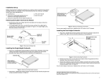
TS/2&3SlotBook Page vii Wednesday, September 4, 1996 10:56 AM TurboStack 2- and 3-Slot Chassis For Use with TurboStack Hubs Installation Manual TS/2&3SlotBook Page i Wednesday, September 4, 1996 10:56 AM Electrical Safety and Installation Requirements U.S. Federal Communications RADIATED ENERGY Note: This equipment has been tested and found to comply with the limits for a Class A digital device pursuant to Part 15 of FCC Rules. These limits are designed to provide reasonable protection against harmful interference when the equipment is operated in a commercial environment. This equipment generates, uses, and can radiate radio frequency energy and , if not installed and used in accordance with this instruction manual, may cause harmful interference to radio communications. Operation of this equipment in a residential area is likely to cause harmful interference in which case the user will be required to correct the interference at his own expense. Note: Modifications or changes not expressly approved of by the manufacturer or the FCC, can void your right to operate this equipment. Canadian Department of Communications This Class A digital apparatus meets all requirements of the Canadian Interference-Causing Equipment Regulations. Cet appareil numérique de la classe A respecte toutes les exigences du Règlement sur le matériel brouilleur du Canada. STANDARDS: This product meets the following standards RFI Emission EN55022 Class A WARNING: In a domestic environment this product may cause radio interference in which case the user may be required to take adequate measures. Immunity EN50082-1 NORMEN: Dieses Produkt erfüllt die Anforderungen der nachfolgenden Normen. Hochfrequenzstörung EN55022 Klasse A WARNUNG: Bei Verwendung zu Hause kann dieses Produkt Funkstörungen hervorrufen. In diesem Fall müßte der Anwender angemessene Gegenmaßnahmen ergreifen. Störsicherheit EN50082-1 Radiofrekvens forstyrrelsesemission EN55022 Klasse A ADVARSEL: I et hjemligt miljø kunne dette produkt forårsage radio forstyrrelse. Bliver det tilfældet, påkræves brugeren muligvis at tage tilstrækkelige foranstaltninger. Immunitet EN50082-1 RFI Emissie EN55022 Klasse A WAARSCHUWING: Binnenshuis kan dit product radiostoring veroorzaken, in welk geval de gebruiker verplicht kan worden om gepaste maatregelen te nemen. Immuniteit EN50082-1 i TS/2&3SlotBook Page ii Wednesday, September 4, 1996 10:56 AM NORMES : ce produit est conforme aux normes de suivantes : Emission d'interférences radioélectriques EN55022 Classe A MISE EN GARDE : dans un environnement domestique, ce produit peut provoquer des interférences radioélectriques. Auquel cas, l'utilisateur devra prendre les mesures adéquates. Immunité EN50082 - 1 Radioaaltojen häirintä EN55022 Luokka A VAROITUS: Kotiolosuhteissa tämä laite voi aiheuttaa radioaaltojen häiröitä, missä tapauksessa laitteen käyttäjän on mahdollisesti ryhdyttävä tarpeellisiin toimenpiteisiin. Kestävyys EN50082-1 Emissione RFI (interferenza di radiofrequenza) EN55022 Classe A AVVERTENZA: in ambiente domestico questo prodotto potrebbe causare radio interferenza. In questo caso potrebbe richiedersi all'utente di prendere gli adeguati provvedimenti. Immunità EN50082-1 RFI stråling EN55022 Klasse A ADVARSEL: Hvis dette produktet benyttes til privat bruk, kan produktet forårsake radioforstyrrelse. Hvis dette skjer, må brukeren ta de nødvendige forholdsregler. Immunitet EN50082-1 Emissão de interferência de radiofrequência EN55022 Classe A AVISO: Num ambiente doméstico este produto pode causar interferência na radiorrecepção e, neste caso, pode ser necessário que o utente tome as medidas adequadas. Imunidade EN50082-1 Emisión RFI EN55022 Clase A ADVERTENCIA: en un entorno doméstico, este producto puede causar radiointerferencias, en cuyo caso, puede requerirse del usuario que tome las medidas que sean convenientes al respecto. Inmunidad EN50082-1 Radiostörning EN55022 Klass A VARNING: Denna produkt kan ge upphov till radiostörningar i hemmet, vilket kan tvinga användaren till att vidtaga erforderliga åtgärder. Immunitet EN50082-1 ii TS/2&3SlotBook Page 1 Wednesday, September 4, 1996 10:56 AM Chassis Endcap and Snap-on Backplane Assembly This installation manual details endcap and backplane assembly procedures for the following ATI chassis products with standard backplanes: ❑ 2-slot TurboStack rackmount chassis ❑ 3-slot TurboStack rackmount chassis Package Contents Before starting the installation, check to see that the chassis package contents are complete. Contact your ATI sales representative if any of the following items are missing or damaged: ❑ Backplane (1) ❑ Endcaps (2) ❑ Endcap screws (8 for 2-slot chassis, or 12 for 3-slot chassis) ❑ Handle screws (8 for 2-slot chassis, or 12 for 3-slot chassis) ❑ Rackmount screws (8 for 2-slot chassis, or 12 for 3-slot chassis) ❑ This user manual ❑ Warranty card Getting Started 1. Identify the two or three hubs you will use in this chassis configuration. 2. Remove the four screws and rubber feet on each module, as shown in Figure 1. If you prefer to place the chassis on the desktop instead of mounting it in a 19-inch relay rack, leave the rubber feet on the bottom unit. Location of rubber feet (4 ea.) Remove rubber feet Re-install unit screws Figure 1: Removing the Rubber Feet 1 TS/2&3SlotBook Page 2 Wednesday, September 4, 1996 10:56 AM 3. Re-install the screws without the rubber feet to prevent the unit from expanding. Store the rubber feet for future use. You are now ready to remove the guiderails. To remove the guiderails: 1. Remove the pre-installed guiderails from both sides of each module, as shown in Figure 2. Remove screws from handle (2 ea.) Remove module side screws (2 ea.) Figure 2: Removing Pre-installed Guiderails 2. Store the guiderails and screws for future use. To install the endcaps: 1. Stack the modules with the connector sides together, as shown in Figure 3. Make sure the master module is the uppermost unit. Master module Connector side of module Figure 3: Stacking the Modules 2 TS/2&3SlotBook Page 3 Wednesday, September 4, 1996 10:56 AM TurboStack 2- and 3-Slot Chassis 2. Turn the modules around so that the back panels are facing you. 3. Align the L-shaped end of each endcap with the backs of the module handles and attach the endcap to the side of the modules, as in Figure 4. Use the screws provided. Endcaps Endcap screws (12 ea.) Figure 4: Attaching the Endcaps to Module Sides 4. Attach the L-shaped end of each endcap to the rear of the module handles, as shown in Figure 5. Use the screws provided. Handles (rear view) Handle screws (2 per handle) Back panel side of modules L-shaped end of endcap Figure 5: Attaching the Endcaps to Module Handles You are now ready to install the chassis in a 19” relay rack. 3 TS/2&3SlotBook Page 4 Wednesday, September 4, 1996 10:56 AM To install the assembled chassis in a 19" relay rack: 1. Use the remaining screws in the chassis package (8 for 2-slot and 12 for 3-slot) to mount the chassis into a relay rack, as shown in Figure 6. Relay rack Rackmount screws Handle doors (open) Figure 6: Installing the Chassis in a Relay Rack 2. Close the handle doors to their flush positions. You are now ready to install the backplane. To install the backplane: Use the same procedure for installing 2-slot or 3-slot backplanes. 4 1. Turn the endcap-attached modules around or orient yourself so that the back panels are facing you. 2. Remove the dust covers from the backs of the modules, if present. 3. Snap the backplane over the interrepeater bus ports at the rear of the chassis assembly, as shown in Figure 7. Note the directions for correct mounting on the backplane unit itself. TS/2&3SlotBook Page 5 Wednesday, September 4, 1996 10:56 AM TurboStack 2- and 3-Slot Chassis Interrepeater bus ports 3-slot backplane Figure 7: Installing the Backplane (Back Panel View) 4. Power up the master module by plugging in the power cord. 5. Repeat Step 4 to power up the remaining modules. 6. Connect your data cables. Your modules are now in operating condition. Troubleshooting a Module If one of the modules in the chassis should fail (fault light stays on) or performance is degraded, refer to the hub installation manual. Using SNMP or Omega management methods may help diagnose the problem. If the hub does not respond, reset the hub as prescribed in this section. To reset a malfunctioning module: Perform this procedure if the module’s fault light stays on. 1. Unplug the power cord from the malfunctioning module. 2. Wait 5 seconds. 3. Plug in the power cord again. If the fault light goes out after initialization, the module is functional. If the fault light still stays on, the module should be replaced. Contact your ATI representative and arrange for a return material authorization (RMA). 5 TS/2&3SlotBook Page 6 Wednesday, September 4, 1996 10:56 AM To replace a failed module in a chassis configuration: 1. Remove the power cords from all modules. 2. Remove the data cables from all modules. Note the location of the connectors. Label them for future reference. 3. Remove the chassis from its 19" relay rack. 4. Disconnect the backplane. 5. Remove the rubber feet from the replacement module and replace screws as needed. 6. Remove the endcaps from the defective module, and re-install on the new module. 7. Re-attach the backplane. 8. Re-install the chassis into the 19" relay rack. 9. Plug in the power cords of the modules, beginning with the master module. 10. Attach the data cables to all modules in the chassis. You are done with module replacement. 6 TS/2&3SlotBook Page 7 Wednesday, September 4, 1996 10:56 AM TurboStack 2- and 3-Slot Chassis Chassis Specifications ❑ Required ventilation clearance on all sides: 7.5 inches (191 mm) ❑ Maximum ambient operating temperature: 40° C ❑ Rack size: Standard 19.0 inch (483 mm) 17.0 in. (432 mm) 9.8 in. (249 mm) 3.5 in. (89 mm) 19.0 in. (483 mm) Figure 8: 2-Slot Rackmount Chassis Dimensions 17.0 in. (432 mm) 9.8 in. (249 mm) 5.2 in. (133 mm) 19.0 in. (483 mm) Figure 9: 3-Slot Chassis Dimensions 7 TS/2&3SlotBook Page viii Wednesday, September 4, 1996 10:56 AM Copyright 1996 Allied Telesyn International Corp. All rights reserved. No part of this publication may be reproduced without prior written permission from Allied Telesyn International Corp. Allied Telesyn International Corp. reserves the right to make changes in specifications and other information contained in this document without prior written notice. The information provided herein is subject to change without notice. In no event shall Allied Telesyn International Corp. be liable for any incidental, special, indirect, or consequential damages whatsoever, including but not limited to lost profits, arising out of or related to this manual or the information contained herein, even if Allied Telesyn International Corp. has been advised of, known, or should have known, the possibility of such damages. Trademarks: Ethernet is a registered trademark of Xerox Corporation. UNIX is a registered trademark of UNIX System Laboratories. Novell and NetWare are registered trademarks of Novell, Inc. Microsoft and MS-DOS are registered trademarks and LAN Manager and Windows for Workgroups are trademarks of Microsoft Corporation. 3Com is a registered trademark of 3Com. PC-NFS is a trademark of Sun Microsystems, Inc. PC/TCP is a registered trademark of FTP Software, Inc. DECnet is a registered trademark of Digital Equipment Corporation.