1
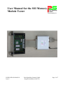
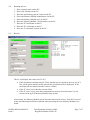
User Manual for the PS/PSL-RD-309/MAN/011
SSI Memory Module
Issue 5
Tester
Park Signalling
Limited
Houldsworth Mill Business Centre
Houldsworth Street,
Stockport SK5 6DA
Tel :
44-(0)161-975-6161
Fax :
44-(0)161-975-6160
[email protected]
www.park-signalling.co.uk
Summary
This document describes how to use the ST 301 SSI Memory Module Tester.
Issues
Issue number:
Date:
Issue 1
Issue 2
November 2007
April 2008
Issue 3
Issue 4
Issue 5
Author
C. Exley
First Issue
Updated to include changes to electrical connections &
interfaces
April 2009
User interface changes requested by Network Rail
April 2009
Amended in line with ISA comments
December 2009
Detailed description of all supplied items added to
Section 2.
Checked
Authorised
M. Duffy
V.G. Patel
…………………………….
Date:
PS/PSL-RD-309/MAN/011
Issue 5
…………………………..
Date:
Park Signalling Limited ©2009
Registered number 03895736
……………………………
Date:
Page 1 of 7
User Manual for the SSI Memory
Module Tester
Park Signalling
Limited
www.park-signalling.co.uk
PS/PSL-RD-309/MAN/011
Issue 5
Park Signalling Limited ©2009
Registered number 03895736
Page 2 of 7
1.
I2TRODUCTIO2
1.1.
Purpose
This document provides instructions on the use of Park Signalling’s ST301 Memory Module
Tester.
1.2.
Scope
This document details how to use the Memory Module Tester.
Note that information on obtaining authorisation / permission to work on a live signalling
system is beyond this document’s scope.
1.3.
Abbreviations
EPROM
RAM
SSI
Tester
UV
Erasable Programmable Read Only Memory
Random Access Memory
Solid State Interlocking
Memory Module Tester
Ultraviolet
PS/PSL-RD-309/MAN/011
Issue 5
Park Signalling Limited ©2009
Registered number 03895736
Page 3 of 7
2.
EQUIPME2T DESCRIPTIO2
2.1.
Supplied Items
The Tester consists of test control software, an interface unit, a mains power supply, an
interface cable and a serial communications lead.
2.2.
•
The software is supplied on a CD and installation on the host PC is described in
Section 4.
•
The interface unit is a metal box (100 x 45 x 110 mm) housing all of the electrical and
electronic circuits of the Memory Module Tester. Mounted on the box are a 40-way
IDC connector for connection to the Memory Module under test, a 9-way D-type
connector for connection to the PC, a barrel-type socket for connection to the power
supply and an ON/OFF switch.
•
The power-supply is a 230V 50Hz to 5V/1A DC switched mode power supply
mounted in a UK plug housing.
•
The interface cable is a ribbon cable with two IDC connectors. Two interface cables
are supplied. One has a 40-way IDC at the interface unit end and a 50-way IDC at the
Memory Module end and is used for Westinghouse MkIII MPMs (Specification
WS1905B) only. The other cable has a 40-way IDC at the interface unit end and a 40way IDC at the Memory Module end and is used for all other MPMs and for PPMs.
•
The serial comms lead has a 9-way D-type socket (female) at both ends to connect the
interface unit to a serial comms port on the host PC.
Storage and Handling
The Tester should be stored in a dry environment with a temperature range of 0-35°C. The
Tester should not be carried by its’ flying leads. When using the Tester, be aware of the trip
hazard presented by the leads. As the Tester is electronic equipment, please dispose of it
responsibly when it is life-expired.
PS/PSL-RD-309/MAN/011
Issue 5
Park Signalling Limited ©2009
Registered number 03895736
Page 4 of 7
3.
DESCRIPTIO2
The Tester consists of test control software, a memory module interface unit, mains power
supply and serial communications lead. The software is designed to run on a PC running
Windows 2000 or later.
SSI Memory Modules contain UV EPROMs and RAM.
The EPROMS contain the main program software and data specific to the railway scheme.
Some versions of the Memory Module use paged memory to access EPROM data.
The Tester is capable of diagnosing the status of the Memory Module under test and provides
a clear indication of any failure found.
Test results may be saved to the PC’s hard drive.
The Tester provides the following functions:
•
•
•
•
4.
Go/No go test of the Memory Module
Identifies checksums of the EPROMs
Tests the RAM
Test the address mapping
SOFTWARE I2STALLATIO2
Administrative rights will be needed in order to carry out the installation.
If the Tester software is not pre-installed on the PC, double-click the ‘MMT_x_yy.msi’ file on
the installation CD (where Tester version = x.yy), and follow the on-screen instructions.
PS/PSL-RD-309/MAN/011
Issue 5
Park Signalling Limited ©2009
Registered number 03895736
Page 5 of 7
5.
OPERATIO2
5.1.
Condition check
Check for any signs of damage, particularly to the connector that mates with the Memory
Module. If the Tester appears to be damaged then do not use it. Contact Park Signalling
immediately and arrange for the Tester to be repaired.
5.2.
Compatibility check
Ensure that the Memory Module to be tested is one of the following:
Testing a Memory Module not included in the list below may result in damage to the Memory
Module and/or to the Tester.
5.2.1. Alstom Memory Modules
•
•
•
SS1311
SS1321
SS1331
5.2.2. GEC Memory Modules
•
•
•
•
•
SS1312
SS1315
SS1316
SS1317
SS1325
5.2.3. Westinghouse Signalling Memory Modules
•
•
•
•
5.3.
E20816/1
E20816/3
E20816/5
E25000/1
Connections & settings
1. Turn on the PC and start the “Memory Module Tester” software.
2. When prompted, select the COM port to which the serial data cable will be connected, and
the file location to save test results in.
3. Connect the power supply to the Tester.
4. Connect the Tester's serial data cable to the serial port of the PC running the Tester
program.
5. Connect the Tester's interface cable to the Memory Module being tested.
6. Turn the Tester on (‘Communications okay’ will be displayed on the screen to confirm
connections).
PS/PSL-RD-309/MAN/011
Issue 5
Park Signalling Limited ©2009
Registered number 03895736
Page 6 of 7
5.4.
Running the test
1.
2.
3.
4.
5.
6.
7.
8.
9.
5.5.
Enter operator name on the PC.
Enter your location on the PC.
Enter the interlocking system’s name on the PC.
Select the Memory Module manufacturer on the PC.
Select the Memory Module type on the PC.
Enter the Memory Module’s serial number on the PC.
Enter the IC4 checksum on the PC.
Enter the IC5 checksum on the PC.
Press the ‘Test module’ button on the PC.
Results
The PC will display the results for IC2-IC5.
•
•
•
If the checksums calculated by the Tester matches those entered by the user, the IC’s
box will be green and the test has passed (the checksums will be displayed). If the
checksums do not match, then the result is a failure.
If the IC’s box is red, then the test has failed.
If the IC’s box is grey, then that component has not been tested (because it is not
present on the type of Memory Module being tested).
After testing, the Memory Module can be disconnected from the Tester. Turn the Tester off
before disconnecting the Memory Module and connecting the next Memory Module to be
tested.
PS/PSL-RD-309/MAN/011
Issue 5
Park Signalling Limited ©2009
Registered number 03895736
Page 7 of 7