1
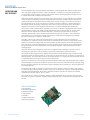
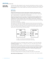
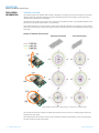
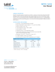
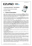
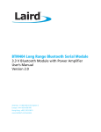
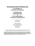
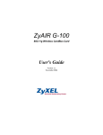
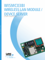
WISMC03BI
WIRELESS LAN MODULE /
DEVICE
SERVER
USER MANUAL
www.lairdtech.com
Innovative Technology
for a Connected World
WISMC03BI
Wireless LAN Module / Device Server
REVISION
HISTORY
2 www.lairdtech.com
REVISION HISTORY
Revision
Description
Laird Technologies
WISMC03BI
Wireless LAN Module / Device Server
TABLE OF
CONTENTS
CONTENTS
WISMC03BI Wireless LAN Module / Device Server ... 4
Firmware Features ..................................................... 15
Overview ...........................................................................4
WISMC03BI Key Features .................................................4
Command Set .................................................................15
Power Saving....................................................................16
Specifications ............................................................... 5
Detailed Specifications ......................................................5
Block Diagram ...................................................................7
Mechanical Specifications ........................................... 8
Wireless LAN Module Dimensional Outline ......................8
Electrical Specifications ............................................... 9
40 Way Hirose Pin Descriptions ........................................9
Absolute Maximum Ratings ...........................................10
Recommended Operating Parameters ...........................10
Application Information ............................................ 17
Antenna Location ...........................................................17
External Antenna..............................................................18
Power Supply Considerations .........................................18
Power-On Reset...............................................................18
Operational Temperature.................................................18
Board to Board Connector and Stacking Height ............19
Hirose Connector General Specification..........................19
Mounting the Module onto the Application Platform....19
Fixing Pillars......................................................................20
Labelling...........................................................................20
Ordering Information.......................................................20
RF Performance Specifications ................................. 12
Transmit Power / Receive Sensitivity ...............................12
Qualification ............................................................... 21
Functional Description ............................................... 13
Qualification Process .......................................................21
Safety Information ..........................................................21
Certifications....................................................................21
Interfaces .........................................................................13
UART Interface ................................................................13
Bluetooth® Coexistence ..................................................14
GPIO Port ........................................................................14
ADC ................................................................................14
3 www.lairdtech.com
Related Documents .................................................... 22
Development Kit .............................................................22
Disclaimers .................................................................. 23
User Manual Status .........................................................23
Laird Technologies
WISMC03BI
Wireless LAN Module / Device Server
OVERVIEW AND
KEY FEATURES
Laird Technologies’ 802.11b/g SLIP Wireless LAN Module is a fully integrated and qualified wireless device
server sub-system, designed to make it simple to embed 802.11 connectivity. It has been designed to be
pin compatible with the footprint of Siemens MC55 GPRS modules, allowing designers to design one pcb
to support either GPRS or Wireless LAN connectivity.
Unlike other wireless modules all of the necessary drivers, protocol stack, security algorithms up to the host
TCP/IP interface are integrated, along with a high performance antenna. The 802.11b/g SLIP Wireless LAN
module is designed for applications with an existing host processor running a TCP/IP stack and provides a
fast and efficient way to convert a product from a wired to a wireless connection. It enables designers to
add wireless internet connectivity to almost any device with a serial port and TCP/IP stack. The module is
designed for the lowest cost of integration and ownership. It is ideal for enabling M2M applications.
The module is a dual processor design, dedicating one processor to the 802.11b/g baseband with a second
powerful ARM7 processor, with 16MB of SRAM and 64MB of flash memory running the wireless drivers,
UDP stack with SLIP interface and command interpreter. Connection to the host device is via a high
speed 921,600 bps UART, with an additional twelve GPIO lines and two 10 bit ADCs. The module has a
comprehensive set of commands giving high level access to wireless network management, simplifying
the task of connecting to the 802.11 infrastructure.
The UART is used to carry both control and data frames. Frames transferred across this interface are
encapsulated in a simple SLIP protocol. Data frames are presented as 802.3 packets; control frames employ
high level commands to configure and control the module’s operation. Because the module integrates the
802.11b/g drivers, it provides independence from the proprietary nature of wireless silicon implementations,
saving a significant amount of development time and making integration totally independent of the host
operating system.
The twelve GPIO and two analogue input lines can be configured using commands to provide control or
monitoring of simple devices such as switches or LEDs without requiring any external processing.
The module includes a high sensitivity, high gain antenna which provides excellent range. Typical open field
performance yields an operating range up to 100 meters. A second 50 Ohm U.FL connection is provided for an
external antenna. This can be used in place of the internal antenna, or in conjunction with the internal antenna
to implement antenna diversity for improved receive performance.
Support is provided for low power modes that make the Wireless LAN module particularly applicable to battery
powered installations. It has been designed to ensure the best co-existence with other devices operating within
the same frequency spectrum and has hardware support designed into the module for 2 and 3-wire Bluetooth®
co-existence schemes.
The Wireless LAN module is supplied in a small pcb form factor (22.8mm x 33.8mm x 7.6mm), that connects
to a main pcb using a 40 way Hirose connector which is pin compatible with the Laird Technologies Bluetooth®
Intelligent Serial Module BISMII. The module is Lead-free and RoHS compliant and supports an industrial
operational temperature range of -40°C to +85°C.
The module has FCC modular certification, Industry Canada certification and CE approval. These approvals
allow users to simplify or bypass RF regulatory testing, enhancing time to market and reducing approvals time
and cost.
APPLICATION AREAS
• POS equipment
• Automotive applications
• Medical equipment
• Street furniture
• Telematics
• Industrial automation
• Metering applications
4 www.lairdtech.com
Laird Technologies
WISMC03BI
Wireless LAN Module / Device Server
SPECIFICATIONS
Categories
Feature
Implementation
Wireless Specification
Standards Supported
IEEE 802.11b, IEEE 802.11g
Frequency
2.412 – 2.484 GHz
Channels
11 channels – USA
13 channels – Europe
4 channels – France (EIRP > 10mW outdoors)
14 channels – Japan
Programmable selection of region
Max Transmit Power
802.11b: +15 dBm @ antenna connector
802.11b: +17 dBmi from integrated antenna
802.11g: +13 dBm @ antenna connector
802.11g: +15 dBmi from integrated antenna
Receive Sensitivity
802.11b: -91dBm @ 1 Mbps, -84dBm @ 11Mbps
802.11g: -84dBm @ 6Mbps, -67dBm @ 54Mbps
Data Rates
54Mbps – 1Mbps with automatic fallback
Data Transfer rate
Up to 921.6kbps (limited by UART)
Modulation Schemes
802.11b – BPSK, QPSK, CCK, DSSS
802.11g – BPSK, QPSK, 16-QAM, 64-QAM, OFDM
Range
Up to 100 metres free space
Connection Modes
Infrastructure and ad-hoc (IBSS)
Integrated Antenna
High performance +2dBi multilayer ceramic
External Antenna
50 Ohm U.FL connection
Antenna Diversity
Supported using integrated and external antennae
Serial Interface
RS-232 bi-directional for commands and data
16550 compatible
Baud Rate
Configurable from 9,600 to 921,600bps
Bits
8
Parity
Odd, even, none
Stop bits
1 or 2
Default Serial parameters
115200,n,8,1
Levels
3.0V CMOS
Modem Control
DTR, DSR, DCD, RI, RTS, CTS †
I/O
12 general purpose I/O pins, 3.0V CMOS†
ADC
2 ADC inputs. 10 bit, 3.0V max
Antenna Modes
UART Interface
General Purpose Interface
†DSR, DTR, RI and DCD are configurable either as GPIO or as modem control lines.
5 www.lairdtech.com
Laird Technologies
WISMC03BI
Wireless LAN Module / Device Server
SPECIFICATIONS
Categories
Feature
Security
Protocols
802.11b, 802.11g
Internet
IPv4, UDP, SLIP
Powersave modes
IEEE Powersave Modes 0,1,2 & 5
Current Consumption
Less than 250mA during data transfer with a configurable low
power mode less than 5mA
Supply
3.3V – 5.0V DC
Regulation
On-board regulators, brown-out detection and watchdog
Specification
ARM7 with 16Mb SRAM and 64Mb Flash
WLAN functions
Search, Attach, Detach, Set Region, etc.
Upgradeability
Firmware upgradeable via UART
Coexistence /
Compatibility
Bluetooth
2-wire and 3-wire hardware coexistence schemes supported
Pin compatible with Laird Technologies BISM Bluetooth modules
Connections
Interface
40 way Hirose DF-12 Connector
External Antenna
U.FL connector for 50 Ohm antenna
Dimensions
22.8mm x 33.8mm x 7.6mm
Weight
8 grams
Operating Temperature
Low Power Mode: -40°C to +85°C
Continuous transmission: -40°C to +60°C
Minimum cold start temperature: -25°C
Storage Temperature
-50°C to +125°C
FCC
Modular Approval PI405W
IC
Industry Canada
CE & R&TTE
Approved
Lead free
Lead-free and RoHS compliant
Warranty
2 Years
Supply Voltage
Embedded Wireless
Processor System
Physical
Environmental
Approvals
Miscellaneous
Open Connection
WEP encryption 64 and 128 bit options
WPA-PSK
WPA2 Enterprise & Personal
IEEE 802.11i-PSK (AES-CCMP)
TKIP Encryption
SSL2 / SSL3 / TLS1
Hardware Acceleration for security features
(Encryption modes require an external supplicant)
Network Drivers
Power Consumption
6 www.lairdtech.com
Implementation
Laird Technologies
WISMC03BI
Wireless LAN Module / Device Server
SPECIFICATIONS
Block Diagram
The module has a 40 way Hirose connector which provides a compatible pin out to the same form factor
Laird Technologies Bluetooth Intelligent Serial Module.
7 www.lairdtech.com
Laird Technologies
WISMC03BI
Wireless LAN Module / Device Server
Mechanical
SPECIFICATIONS
Wireless LAN Module Dimensional outline
All dimensions in mm
Notes
1. RF antenna
2. External Antenna connector (Hirose U.FL-R-SMT)
3. Board to board connector (Hirose connector)
4. 2.0mm maximum top side component height (excluding antenna)
5. 1.5mm maximum bottom side component height
6. 3.8mm max. pcb clearance for fixings body (top and bottom)
7. 40 way connector footprint
8. 2.2 +/- 0.075 fixing holes x 3
The Module is equipped with a 40-pin 0.5mm pitch board-to-board connector that connects to
the application platform.
8 www.lairdtech.com
Laird Technologies
WISMC03BI
Wireless LAN Module / Device Server
Electrical
SPECIFICATIONS
40 way Hirose Pin Descriptions
The Hirose DF12C board-to-board connector on the module is a 40-pin double-row receptacle.
The table below defines the pin functions. The pin-out is as viewed from the underside of the Module.
Pin
Signal
Description
1
2
3
4
5
6
7
8
9
10
11
12
13
14
15
16
17
18
19
20
21
22
23
24
25
26
27
28
29
30
31
32
33
34
35
36
37
38
39
40
ADC 0
GPIO1
ADC 1
GPIO2
WLAN_ACTIVE
UART_RI
N/C
UART_DCD
N/C
UART_DSR
GND
UART_DTR
RESET
GPIO4
GND
GPIO5
N/C
GND
UART_CTS
N/C
UART_TX
WAKEUP
UART_RTS
BT_PRIORITY
UART_RX
N/C
VCC_3V
VCC_5V
VCC_5V
GND
VCC_5V
N/C
GPIO6
N/C
GPIO7
GND
GPIO8
GND
GPIO9
BT_STATE
3.0 V Max
I/O for Host.
3.0 V Max
I/O for Host
Output
RING or GPIO12
DCD or GPIO13
DSR or GPIO10
DTR or GPIO11
Reset Input
I/O for Host
I/O for Host
Clear to Send Input
Transmit Data Output
Reserved
Request to Send Output
Input
Receive Data Input
3.0V Monitor
Supply
Supply
Supply
I/O for Host
I/O for Host
I/O for Host
I/O for Host
Input
Notes:
The reset circuitry within the module incorporates a brown-out detector. The reset pin has a fixed 10kOhm pull down
resistor to ground, followed by a 10kOhm resistor feeding the base of a transistor.
GPIO lines can be configured through software to be either inputs or outputs. At reset, all GPIO lines, other than those
that have dual functionality as modem control signals are configured as inputs.
UART_RX, UART_TX, UART_CTS, UART_RTS, UART_RI, UART_DCD, UART_DTR and UART_DSR are all 3.0v level logic.
When the signal sits at 3.0V it is de-asserted. When the signal is at 0V it is asserted.
UART_RX, UART_TX, UART_CTS, UART_RTS are controlled directly by the module. The operation of UART_RI, UART_DCD
and UART_DTR is user programmable.
Pin 27 (VCC_3V) may only be used for monitoring purposes. It must not be used as a current source.
Pin 22 (WAKEUP) will be used for future powersave functionality. It has an internal 100kOhm pull-up.
ADC inputs (pins 1 and 3) are read using commands over the UART.
UART_DSR is used to signal the module to enter Power Save Mode 2.
Pins marked N/C may have internal connections within the module and should not be connected to any external circuitry.
9 www.lairdtech.com
Laird Technologies
WISMC03BI
Wireless LAN Module / Device Server
Electrical
SPECIFICATIONS
Absolute Maximum ratings
Absolute maximum ratings for supply voltage and voltages on digital and analogue pins of the
Module are listed below. Exceeding these values will cause permanent damage.
Parameter
Min
Peak current of power supply
Max
Unit
550
mA
Voltage at digital pins
-0.3
3.3
V
Voltage at VCC_5V pin
3.3
5
V
Recommended Operating Parameters
Power Supply
Signal Name
Pin No
Voltage level
Comments
VCC_5V
28, 29, 31
3.3V to 5.0V
Ityp = 250mA.
All VCC_5V pins should be connected
GND
11,15,18,30,36,38
All six GND pins should be connected
Signal Levels for Interface and GPIO
Signal Type
Signal level Signal level @ 0mA load Signal level @ 4mA load
Input
VILmax=0.8V
VIHmin=2.1V
VIHmax=3.3V
Output
VOLmax=0.2V
VOHmin=2.8V
VOLmax=0.4V
VOHmin=2.6V
RS-232 Interface
Signal Name
Pin No
I/O
UART_TX
21
O
Comments
UART_RX
25
I
UART_CTS
19
I
UART_RTS
23
O
UART_DSR
10
I
Used to place the module in Powersave 2 mode
UART_DTR
12
O
Direction is programmable – default is Output
UART_RI
6
O
Direction is programmable – default is Output
UART_DCD
8
O
Direction is programmable – default is Output
This pin must NOT be pulled low by external circuitry.
General Purpose I/O and ADC
Signal Name
Pin No
I/O
Comments
GPIO 1 - 9
2,4,14,16,33,35,37,39
I or O
There is no GPIO3
GPIO 10 – 13
10,12,6,8
I or O
Shared with DSR, DTR, RI, DCD
ADC0, ADC1
1, 3
I
Range 0 – 3.0V
Other Functions
Signal Name
10 www.lairdtech.com
Pin No
I/O
RESET
13
I
Comments
Active high. The RESET line has a fixed 10kOhm pull down
resistor to ground, followed by a 10kOhm resistor feeding
the base of a transistor.
3VOUT
27
O
Used to monitor the state of the regulated supply within
the module. THIS PIN MUST NOT BE USED TO POWER AN
EXTERNAL CIRCUIT.
Laird Technologies
WISMC03BI
Wireless LAN Module / Device Server
Electrical
SPECIFICATIONS
Signal Levels for Bluetooth Coexistence and Wakeup Pins
Signal Type
Signal level
Input
VILmax=1.0V
VIHmin=1.5V
VIHmax=3.5V
Output
VOLmax=0.4V
VOHmin=2.4V
Bluetooth Coexistence
Signal Name
Pin No
I/O
WLAN_ACTIVE
5
O
Comments
BT_PRIORITY
24
I
If unused, this pin should be pulled low.
BT_STATE
40
I
If unused, this pin should be pulled low
Pin No
I/O
22
I
Wakeup
Signal Name
WAKEUP
11 www.lairdtech.com
Comments
Reserved for future use. The WAKEUP line has a fixed
100kOhm pull-up resistor.
Laird Technologies
WISMC03BI
Wireless LAN Module / Device Server
RF Performance
Specifications
Transmit Power (802.11G)
Conducted Transmit Power
Typ: +13 dBm
Antenna Gain (Integrated Antenna)
+2dBi typ.
Effective Transmit Power
Typ:+15dBmi
Transmit Power (802.11b)
Conducted Transmit Power
Typ: +15 dBm
Antenna Gain (Integrated Antenna)
+2dBi typ.
Effective Transmit Power
Typ:+17dBmi
Receive Sensitivity (802.11b)
Receive Sensitivity (11Mbps)
Typ: -84 dBm
Antenna Gain (Integrated Antenna)
+2dBi typ.
Effective Receive Sensitivity
-86dBm
Receive Sensitivity (802.11G)
12 www.lairdtech.com
Conducted Transmit Power
Typ: -82dBm
Antenna Gain (Integrated Antenna)
+2dBi typ.
Effective Receive Sensitivity
-84dBm
Laird Technologies
WISMC03BI
Wireless LAN Module / Device Server
Functional
Description
The Wireless LAN module is designed for use with a host system that implements a TCP/IP stack. It provides a
UDP stack and SLIP interface to allow fast integration. The integrated, high performance antenna together with
the RF and baseband circuitry provides the Wireless LAN connectivity and the UART interface for a connection
to a host system.
Interfaces
UART Interface
Modem signal nomenclature can be a source of great confusion, particularly on devices which can be
configured in either DCE (Data Communications Equipment) or DTE (Data Terminal Equipment) format.
For the purpose of this data sheet all UART signals are defined on the assumption that the module is being
used as a conventional DCE. I.e it is behaving like a serial PSTN modem.
UART_TX, UART_RX, UART_RTS and UART_CTS form a conventional asynchronous serial data port with
handshaking, conforming to the ITU-T v.24 standard for DCE signalling. The interface is designed to operate
correctly when connected to other UART devices such as a 16550A. Note that the signalling levels are a
nominal 0V and 3.0V and are inverted with respect to the signalling on an RS232 cable. The interface is
programmable over a variety of baud rates, with no, even or odd parity, one or two stop bits and hardware
flow control. Non-standard baud rates are supported – for more information please contact Laird Technologies.
Auto-bauding is not supported.
On power-up the UART defaults to 115200,n,8,1.
Note that there is no standardization regarding the nomenclature of RX and TX across a DCE-DTE interface.
Some implementations show TX(DCE) connected to TX(DTE) to give naming consistency across a cable, whereas
other show TX driving RX to reflect logical port directions. Always check the direction of ports on DCE and DTE.
In a DCE mode, where the module is being driven as a peripheral by a host processor application, the UART
signals should be connected according to the following scheme:
Port UART_TX transmits data to the application’s /RXD input.
Port UART_RX receives data from the application’s /TXD output.
Two-way hardware flow control is implemented by UART_RTS and UART_CTS. In DCE mode, UART_RTS is
an OUTPUT and is active low. UART_CTS is an INPUT and is active low. These signals operate according to
normal industry convention.
Some serial implementations link UART_CTS and UART_RTS to remove the need for handshaking. Laird
Technologies does not recommend linking UART_CTS and UART_RTS other than for testing and prototyping.
If these pins are linked and the host sends data at the point that the Wireless Module deasserts its UART_RTS
signal, then there is a significant risk that internal receive buffers will overflow which could lead to a loss
of data. Laird Technologies recommend that the correct UART_CTS to UART_RTS handshaking protocol
be adhered to in order to ensure proper operation.
The UART_DSR signal is an input to the module to place it in Powersave Mode 2.
The operation, meaning and direction of the UART_RI and UART_DCD signals is user programmable.
Note that the serial module output is at 3.0V CMOS logic levels. Level conversion must be added to interface
with an RS-232 level compliant interface.
13 www.lairdtech.com
Laird Technologies
WISMC03BI
Wireless LAN Module / Device Server
Functional
Description
Bluetooth Coexistence
Three pins are provided to allow implementation of Bluetooth coexistence schemes, when the 802.11 module
is collocated with a Bluetooth radio. These connect directly between the basebands of the two radios to ensure
minimum interference. Both 2-wire and 3-wire coexistence schemes can be supported.
Coexistence requires that the Bluetooth radio meets at least version 1.2 of the Bluetooth standard and supports
Adaptive Frequency Hopping (AFH).
GPIO Port
Twelve lines of programmable bi-directional input/outputs (I/O) are provided that can be accessed via the UART
port with the IO family of commands. These can be used as data inputs or to control external equipment.
Each of the GPIO pins can be independently configured to be either an Input or Output. A selection of ports
can be accessed synchronously.
Four of the lines (GPIO 10-13) are shared with modem control functions. If they are used to implement a fully
featured UART, then they cannot be used for GPIO.
ADC
The Wireless LAN module provides access to two 10-bit ADCs. These provide an input range of 0V to 3.0v.
Suitable external scaling and over-voltage protection should be incorporated in your design.
Please refer to the WISM ADC Application Note AN017 for information on interfacing the ADC pins.
14 www.lairdtech.com
Laird Technologies
WISMC03BI
Wireless LAN Module / Device Server
Firmware
Features
Command Set
The module supports the following commands.
Details of the complete command list are provided in a separate Programming Guide, the following are a
provided as an overview.
Command
Parameters
Operation
UARTMODIFY
Baud: Baud rate (9600, 19200, 38400,
57600, 115200, 230400, 921600)
Configures the UART parameters.
Length: 8 bits (only allowed option)
Parity: Even / Odd
Stop: 1, 2
SECURITY
Flag: none, WEP
Selects use of WEP security.
(See firmware release notes for other
security parameters)
KEY
AUTHENTICATE
Keystring: 10 or 26 Hex digits setting 64
or 128 bit encryption key
Sets the WEP encryption key.
Flag: Open or closed
Selects authentication strategy to use in
combination with WEP.
SEARCH
ATTACH
Performs a search for local Access Points.
Name: Alphanumeric AP SSID
Detaches the module from the current
Access Point.
BSSTYPE
Selects either AP or ad-hoc mode
of operation.
Channel: 1-11 (Europe), 1-13 (US),
and 1-14 (Japan)
MACADDRESS
POWERSAVE
Attaches the module to the specified
Access Point.
DETACH
CHANNEL
15 www.lairdtech.com
(See firmware release notes for other
security parameters)
Sets the operating channel for an
ad-hoc network.
Reads back the MAC address of
the module.
Flag: Powersave mode (0,1,2,5)
Selects the power save mode.
GETRSSI
Reports signal strength information for the
current AP connection.
GETREGION
Gets the current region for which the
module is configured.
SETREGION
Sets the region.
INITADCCHANNEL
Initializes the ADC for a particular channel.
READADCCHANNEL
Reads the specified ADC channel.
CFGGPIOOUTPUT
Set PIO line(s) to be outputs
CFGGPIOINPUT
Set PIO line(s) to be inputs
SETGPIO
Set output line(s) high
CLEARGPIO
Set output line(s) low
READGPIO
Reads state of input GPIO line(s)
Laird Technologies
WISMC03BI
Wireless LAN Module / Device Server
Firmware
Features
Power Saving
The module supports the Wireless LAN IEEE power saving function. When this power saving mode is enabled,
the wireless LAN chipset goes to sleep when it is not actively receiving from the access point. The chipset
wakes up on a regular basis to receive broadcast messages from the AP or to transmit or receive unicast
messages. By using this technique the average power consumption of the chipset is reduced from around
250mA in active receive mode to less than 35mA. The Laird Technologies module offers IEEE power save
operation in three different modes:
• Powersave mode 1: The wireless LAN chipset operates in IEEE powersave mode and the module
microcontroller remains fully awake and ready to receive commands and data from the host.
This mode of power saving reduces the average consumption of the module to <35mA.
•
Powersave mode 2: The wireless LAN module operates in IEEE powersave mode and the module
microcontroller is put into a very low power standby mode. The average current consumption in
this mode is reduced to <5mA. In power save mode 2, UART_DSR is used by the host to indicate
that the module can enter the low power state. When UART_DSR is de-asserted, the module
microcontroller enters low power standby. The microcontroller will re-start when either a packet
is received from the AP or the host requests it by asserting UART_DSR.
•
Powersave mode 5: The modules default mode of start up is in Powersave mode 5. At start up
the module automatically enters Power Save 5 mode. The average current consumption in this
mode is reduced to <25mA. In this mode the module powers down the WLAN chipset, and awaits
commands from the host. The host may only send the following commands:
o UARTMODIFY
o POWERSAVE
o MACADDRESS
o VER
In Powersave mode 5 no other commands will be accepted by the module until it has entered either Power
Save 1 or Power Save 0 mode.
Powersave mode 1 requires beacons to be broadcast from an infrastructure access point. Therefore it is not
available when operating in ad-hoc (IBSS) mode.
16 www.lairdtech.com
Laird Technologies
WISMC03BI
Wireless LAN Module / Device Server
Application
Information
Antenna Location
The antenna used on the Wireless LAN module is designed to be largely immune from the effects of proximity
detuning. Normally, antennas operating at 2.4GHz are affected by their surroundings, so that great care is
needed in their placement and orientation.
The Wireless LAN module can be used in most locations and orientations and is only marginally affected by the
presence of a significant ground plane in close proximity.
The antenna distribution is close to isotropic, which means that the orientation of mounting has only a limited
effect on the overall range. However the optimum range is achieved when the two antennae are directly facing
each other.
Example of Radiation Characteristics
Horizontal Polarization
Vertical Polarization
Typical Radiation Characteristics. Measured at 2.5 meters from a standard dipole.
The module should not be located in a sealed metal enclosure, as this will act as a Faraday cage and severely
attenuate the radio signal.
The antenna finish may tarnish as a result of environmental conditions and handling. This is a cosmetic effect
and does not affect the RF performance.
17 www.lairdtech.com
Laird Technologies
WISMC03BI
Wireless LAN Module / Device Server
Application
Information
External Antenna
The approval of the module was performed using a 3dBi external antenna from RF Castle Electronics
(www.rfcastle.com/pdf/RF-3dbi%20DipoleA.pdf). The antenna was connected using a short cable to
convert from the U.FL connector on the module to a reverse SMA. The conditions of approval allow the
use of an alternative antenna, but require that the resulting effective radiated power does not exceed
that exhibited during the approvals testing.
To ensure that the approval is not affected, the TOTAL GAIN of the external antenna, including insertion
loss of the connectors and cable must be less than 3dBi. If a higher gain is employed, then the pre-approved
status of the module will be lost. Customers must also ensure that the frequency characteristic of their
antenna matches that of the antenna used for approval. As antennae are tuned for their frequency band
the use of a different antenna technology may result in a change in emissions outside the 2.4GHz band.
It is the customer’s responsibility to ensure that an external antenna does not negate the approval.
U.FL connectors are supplied from a number of connector manufacturers. Details of Hirose’s mating
U.FL connectors are available at http://www.hirose.co.jp/cataloge_hp/e32119372.pdf
Power Supply Considerations
The power supply for the Module must be a single voltage source within the range of 3.3 V to 5.0 V.
It must be able to provide sufficient current for a transmit burst. This can rise to 550mA.
The Module includes on-board regulators to provide local 3.0V. This rail is accessible on pin 27 for
monitoring purposes only. Under no circumstances should this pin be used to source current.
Power (VCC_5V) is provided via the board-to-board connector Pins 28, 29 and 31. All VCC_5V and
GND pins should be connected to ensure that individual pin current capacities are not exceeded during
transmit current peaks.
Power-On-Reset
The Module is provided with an active high reset pin (Hirose 40way DF12C connector pin 13). However,
on the application of power, the Power On Reset circuit built into the Module will ensure that the unit
starts correctly. The external reset signal allows the module to be reset under software control from the
host. After a power on or reset operation, the module will de-assert the UART_RTS output and re-assert
it when it is ready to receive commands.
Operational Temperature
The Wireless LAN module is designed to meet an operational temperature of -40°C to +85°C in normal
operation where it is running in IEEE power save mode.
If the module is run in a mode that results in more frequent receive and transmit activity the operating
temperature will need to be derated to ensure that overall module power dissipation limits are not exceeded.
When the ambient temperature rises above 60°C the module should only be operated in powersave mode
1 or higher.
The Wireless LAN module can operate in temperatures as low as -40°C, but the cold start minimum
temperature must not be below -25°C.
18 www.lairdtech.com
Laird Technologies
WISMC03BI
Wireless LAN Module / Device Server
Application
Information
Board to board connector and stacking height
The WISM connects to a motherboard by means of a board-to-board connector that is supplied by Hirose.
Mating headers from Hirose are available in different stacking heights, allowing the spacing between the
WISM module and carrier pcb to be changed from 3.5mm to 5.0mm.
Item
Part number
Stacking height
HRS number
Receptacle on Module
DF12C-40DS-0.5V(86)
3.5 mm – 5 mm
CL537-0007-7-86
Headers DF12 series
DF12(3.5)-40DP-0.5V(86)
DF12(4.0)-40DP-0.5V(86)
DF12(5.0)-40DP-0.5V(86)
3.5 mm
4.0 mm
5.0 mm
CL537-0032-4-86
CL537-0057-5-86
CL537-0157-0-86
Notes:
The headers listed above are with boss and metal fitting.
Suffix -86 denotes RoHS compliance.
Hirose Connector general specification
Parameter
Specification (40 pin Board to Board connector)
Number of Contacts
40
Quantity delivered
2000 Connectors per Tape & Reel
Voltage
50V
Current Rating
0.5A max per contact
Resistance
0.05 Ohm per contact
Dielectric Withstanding Voltage
500V RMS min
Operating Temperature
-45°C to +125°C
Contact Material
phosphor bronze (surface: gold plated)
Insulator
Material PA , beige natural
Stacking height
3.0 mm ; 3.5 mm ; 4.0 mm ; 5.0 mm
Insertion force
21.8N
Withdrawal force 1st to 50th
10N
Maximum connection cycles
50
See http://www.hirose.co.jp/cataloge_hp/e53700036.pdf for detail information on the PCB socket.
Mounting the Module onto the application platform
There are many ways to properly install the Module in the host device. An efficient approach is to mount
the PCB to a frame, plate, rack or chassis. Fasteners can be M1.8 or M2 screws plus suitable washers, circuit
board spacers, or customized screws, clamps, or brackets in 2.2mm diameter holes. Note that care should be
taken to ensure the head of the fixing does not interfere with the circuit. Nylon fixings are recommended.
The antenna (brown square component on top side of PCB) must not be influenced by any other PCBs,
components or by the housing of the host device. The proximity of the antenna to large metallic objects
can affect the range and performance of the system. Designers should carefully consider the location of
the Module and the type of enclosure material that is used.
To prevent mechanical damage, be careful not to force, bend or twist the Module. Be sure it is positioned
flat against the host device.
19 www.lairdtech.com
Laird Technologies
WISMC03BI
Wireless LAN Module / Device Server
Application
Information
Fixing Pillars
Laird Technologies in conjunction with Richco has designed a mounting pillar for use with the Wireless LAN
Module. This allows the module to be securely held to a primary pcb using snap fit details. A variety of heights
are available to accommodate different variants of Hirose stacked connectors. Pillars supporting a 3.5mm
stacked board height can be supplied by Laird Technologies. These and alternative spacings can also be
ordered directly from Richco.
Customer designs using these pillars should use 2.5mm diameter holes on a 1.6m m thick PCB.
Board Spacing
Part number
Source
Matching HRS PCB Socket
3.6 mm
NPR2005-153-3.6
Laird Technologies / Richco
CL537-0032-4-86
4.1 mm
NPR2005-153-4.1
Richco
CL537-0057-5-86
5.1 mm
NPR2005-153-5.1
Richco
CL537-0157-0-86
Labelling
The label contains the part number, firmware version loaded at manufacture, serial number, and statutory
approvals information.
Ordering Information
The WISM described in this data sheet should be ordered using the part number below:
20 www.lairdtech.com
Part Number
Description
WISMC03BI
802.11b/g Wireless LAN SLIP Module (40 pin)
Laird Technologies
WISMC03BI
Wireless LAN Module / Device Server
Qualification
Qualification Process
The following safety precautions must be observed during all phases of the operation, usage, service or repair
of any application incorporating this Module. Manufacturers of the RF equipment are advised to convey the
following safety information to users and operating personnel and to incorporate these guidelines into all
manuals supplied with the product. Failure to comply with these precautions violates safety standards of design,
manufacture and intended use of the product. Laird Technologies assumes no liability for customer failure to
comply with these precautions.
Safety Information
If the WLAN module is used in equipment that might be taken and operated on a commercial flight, the
following safety instructions, or similar warning should be added to the user manual.
“Switch off the Wireless device before boarding an aircraft. Make sure it cannot be switched on inadvertently.
The operation of wireless appliances in an aircraft is forbidden by many airlines to prevent interference with
communications systems.”
Certifications
FCC and Industry Canada Statements
This device complies with part 15 of the FCC Rules. Operation is subject to the following two conditions:
(1) This device may not cause harmful interference, and (2) this device must accept any interference received,
including interference that may cause undesired operation.
Changes or modifications not expressly approved by the party responsible for compliance could void the user’s
authority to operate the equipment.
To inherit the modular approval, the antennas for this transmitter must be installed to provide a separation
distance of at least 20 cm from all persons and must not be co-located or operating in conjunction with any
other antenna or transmitter.
Co-location with other radio transmitting devices operating concurrently in the same band will require
additional testing and certification.
Designers should note the distinction that the FCC makes regarding portable and mobile devices. Mobile
devices are defined as products that are not used closer than 20cm to the human body, whereas portable
devices can be used closer that 20cm to the body. In the case where the WISM module is used in a portable
device, additional SAR testing must be performed on the complete product.
FCC Labelling requirement
If the FCC ID is not visible when the module is installed inside another device, then the outside of the device
into which the module is installed must also display a label referring to the enclosed module. This exterior label
can use wording such as the following: “Contains Transmitter Module FCC ID: PI405W” or “Contains FCC ID:
PI405W.” Any similar wording that expresses the same meaning may be used.
National RF approvals
A list of the countries where the Module is approved will be provided by Laird Technologies as required. As a
minimum the product is listed in Europe, Scandinavia, Canada and USA. Laird Technologies assumes no liability
for customer failure to comply with national RF approval.
R&TTE Notification Requirement
The 2.4GHz band has some restrictions within the EU when the transmit power level is greater than 10mW
(R&TTE Class 2). Because of this, it is designated within R&TTE as a non-harmonised band. Such products
must be notified to the appropriate Notified Body within each country where it is placed on the market. Laird
Technologies has notified the WISM module, but manufacturers incorporating it within their products and
intending to sell these within Europe have a responsibility to notify the appropriate nominated body before
commercial introduction. A list of nominated bodies is available at:
http://eur-lex.europa.eu/LexUriServ/site/en/oj/2003/c_302/c_30220031212en00010414.pdf
Further details on the notification procedure are given in Laird Technologies’ Application Note AN016 Notification Requirements for Wireless Products.
21 www.lairdtech.com
Laird Technologies
WISMC03BI
Wireless LAN Module / Device Server
Related
Documents
Related Documents
AN008 - Wireless Development Kit User Guide
AN016 - Notification Requirements for Wireless Products.
AN017 – Interfacing to the WISM ADC input
WHP-050004-1V0 Bluetooth and 802.11 Coexistence
WISM SLIP Programming Manual
Documents are available for download from www.lairdtech.com
Development Kit
Laird Technologies offers a Wireless Development Kit for embedded developers which is unique in supporting
Bluetooth, 802.11 and GSM/GPRS. It provides a simple design environment that can dramatically reduce the
development time of wirelessly enabled products.
The Wireless Development Kit is available with Laird Technologies’ pre-qualified Bluetooth and 802.11 Wireless
LAN modules and accepts both 40 pin and 50 pin versions of these modules.
Laird Technologies’ modules contain embedded protocol stacks, removing the need for complex programming
on a host processor.
Features:
Bluetooth
• Complete, qualified Bluetooth stack
• Support for Version 2.0
• Upgradeable for Bluetooth 2.1 when available
• Simple AT style programming interface
• Audio codec evaluation kits available
802.11b/g
• Enhanced drivers for low power operation
• Robust TCP/IP stack or UDP/SLIP
• Integrated Web Server (TCP/IP version only)
• Embedded interpreter (UWScript) for fast development (TCP/IP version only)
A range of codec audio development boards for Bluetooth voice applications are available. These can be
plugged into the wireless development kit for rapid of audio applications.
For cellular applications, the Wireless Development Kit also supports Siemens’ MC55 range of GSM/GPRS
modules, which are pin compatible with Laird Technologies’ wireless LAN module. This permits designers
to develop products which can support either short range or wide area wireless connectivity, with incredibly
fast time to market.
22 www.lairdtech.com
Laird Technologies
WISMC03BI
Wireless LAN Module / Device Server
Disclaimers
Laird Technologies’ WIRELESS PRODUCTS ARE NOT AUTHORISED FOR USE AS CRITICAL COMPONENTS
IN LIFE SUPPORT DEVICES OR SYSTEMS WITHOUT THE EXPRESS WRITTEN APPROVAL OF THE MANAGING
DIRECTOR OF Laird Technologies.
The definitions used herein are:
a) Life support devices or systems are devices which (1) are intended for surgical implant into the body, or (2)
support or sustain life and whose failure to perform when properly used in accordance with the instructions for
use provided in the labelling can reasonably be expected to result in a significant injury to the user.
b) A critical component is any component of a life support device or system whose failure to perform can
be reasonably expected to cause the failure of the life support device or system, or to affect its safety or
effectiveness.
Laird Technologies does not assume responsibility for use of any of the circuitry described, no circuit patent
licenses are implied and Laird Technologies reserves the right at any time to change without notice said circuitry
and specifications.
User Manual Status
Laird Technologies reserve the right to change the specification without prior notice in order to improve the
design and supply the best possible product. Updated information, firmware and release notes will be made
available on www.lairdtech.com.
Please check with Laird Technologies for the most recent data before initiating or completing a design.
global solutions: local support
USA: +1.800.492.2320
Europe: +44.1628.858.940
Asia: +852.2268.6567
[email protected]
www.lairdtech.com/wireless
23 TM
Laird Technologies is the world leader in the design and
manufacture of customized, performance-critical products for
wireless and other advanced electronics applications.
Laird Technologies partners with its customers to find
solutions for applications in various industries such as:
Network Equipment
Telecommunications
Data Communications
Automotive Electronics
Computers
Aerospace
Military
Medical Equipment
Consumer Electronics
Laird Technologies offers its customers unique
product solutions, dedication to research and
development, as well as a seamless network of
manufacturing and customer support
facilities across the globe.
LWS-UM-WISMC03BI 0409
Copyright © 2009 Laid Technologies, Inc. All rights reserved.
The information contained in this manual and the accompanying software programs are copyrighted and all rights are reserved by Laird Technologies, Inc. Laird Technologies, Inc. reserves the right to make periodic
modifications of this product without obligation to notify any person or entity of such revision. Copying, duplicating, selling, or otherwise distributing any part of this product or accompanying documentation/software
without the prior consent of an authorized representative of Laird Technologies,Inc. is strictly prohibited.
All brands and product names in this publication are registered trademarks or trademarks of their respective holders.
This material is preliminary
Information furnished by Laird Technologies in this specification is believed to be accurate. Devices sold by Laird Technologies are covered by the warranty and patent indemnification provisions appearing in its Terms
of Sale only. Laird Technologies makes no warranty, express, statutory, and implied or by description, regarding the information set forth herein. Laird Technologies reserves the right to change specifications at any
time and without notice. Laird Technologies’ products are intended for use in normal commercial and industrial applications. Applications requiring unusual environmental requirements such as military, medical lifesupport or life-sustaining equipment are specifically not recommended without additional testing for such application.
Limited Warranty, Disclaimer, Limitation of Liability
For a period of one (1) year from the date of purchase by the OEM customer, Laird Technologies warrants the OEM transceiver against defects in materials and workmanship. Laird Technologies will not honor this
warranty (and this warranty will be automatically void) if there has been any (1) tampering, signs of tampering; 2) repair or attempt to repair by anyone other than an Laird Technologies authorized technician. This
warranty does not cover and Laird Technologies will not be liable for, any damage or failure caused by misuse, abuse, acts of God, accidents, electrical irregularity, or other causes beyond Laird Technologies’ control,
or claim by other than the original purchaser. In no event shall Laird Technologies be responsible or liable for any damages arising: From the use of product; From the loss of use, revenue or profit of the product; or
As a result of any event, circumstance, action, or abuse beyond the control of Laird Technologies, whether such damages be direct, indirect, consequential, special or otherwise and whether such damages are incurred
by the person to whom this warranty extends or third party. If, after inspection, Laird Technologies’ determines that there is a defect, Laird Technologies will repair or replace the OEM transceiver at their discretion. If
the product is replaced, it may be a new or refurbished product.
24