1
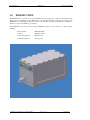
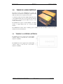
Microair Avionics Pty Ltd
Airport Drive
Bundaberg
Queensland 4670
Australia
Tel:
+61 7 41 553048
Fax:
+61 7 41 553049
e-mail: [email protected]
Microair Avionics
T2000UAV-S
Install and User Manual
About This Document
This supplement describes the installation option, and software
controls for the T2000UAV-S transponder, operating with
software revision T2000UAV-S_1R6.5.
Microair reserves the right to amend this supplement as required,
to reflect any enhancements or upgrades to the T2000
transponder series.
© Microair Avionics Pty Ltd
REVISION STATUS
Revision
1.0
1.1
1.2
01R1-3
01R1-4
01R1-5
01R1-6
01R1-7
01R1-8
01R1-9
Date
18/01/06
29/03/06
01/04/06
04/05/06
21/11/06
24/01/08
12/05/08
25/02/09
24/04/09
01/06/09
Change
Separated from the T2000UAV (Rev 1.4) manual
Additional installation data added
Additional command set data added
Weight data amended
SMA version deleted & Encoder data added
N command deleted
Warranty Statement Update
Updated Limited Warranty Statement
Change email to [email protected]
Ping function amended
The T2000UAV-S Transponder is not a TSO’d product.
T2000UAV-S Installation and User Manual 01R1-9
Page 2 of 24
1st June 2009
Microair Avionics
T2000UAV-S
Install and User Manual
TABLE OF CONTENTS
1.0
INTRODUCTION
4
2.0
T2000UAV-S DESCRIPTION
5
2.1
3.0
3.1
3.2
3.3
3.4
3.4.1
3.4.2
3.4.3
3.4.4
3.4.5
3.4.6
3.4.7
3.4.8
3.4.9
3.4.10
T2000UAV-S ANTENNA OPTIONS
5
SOFTWARE CONTROL
6
THE UAV-S TERMINAL SOFTWARE
THE UAV COMMAND STRUCTURE
DATA SPEED
VALID COMMANDS
Standby (s=t)
Mode 3A (s=a)
Mode C (s=c)
Ident (i=s)
Altitude (a=?)
Altitude Source (d=?)
Encoder Power (e=?)
Voltage (v=?)
Reply Annunciator (r=y)
Ping Function (p=?)
6
7
7
8
9
9
9
9
9
9
10
10
10
10
4.0
T2000UAV-S INSTALLATION
11
5.0
T2000UAV-S TIE DOWN STRAP
12
6.0
MODE C ENCODER
12
7.0
ANTENNA
13
8.0
COAXIAL CABLE
13
9.0
WIRING
9.1
9.2
9.3
9.4
9.5
14
CABLING
POWER ON/OFF
SUPPRESSION IN / OUT
EXTERNAL STANDBY
EXTERNAL IDENT
14
15
15
15
15
10.0
TECHNICAL DRAWING
16
11.0
WIRING DIAGRAMS
17
12.0
PIN ASSIGNMENTS
22
13.0
SPECIFICATIONS
23
14.0
LIMITED WARRANTY
24
T2000UAV-S Installation and User Manual 01R1-9
Page 3 of 24
1st June 2009
Microair Avionics
1.0
T2000UAV-S
Install and User Manual
INTRODUCTION
The T2000UAV-S is a special version of the T2000 Transponder, designed for operation in unmanned aircraft.
This product is not TSO’d due to the OEM nature of the management software. The system consisting of the
T2000UAV-S, and the OEM’s management software control should collectively be submitted for compliance to
TSO C74c, as part of the OEM’s type certificate.
The T2000UAV-S is based upon the certified T2000SFL transponder, and is known to comply with the
following:
Environmental:
Software:
Transponder Function:
RTCA/DO-160D
RTCA/DO-178B
RTCA/DO-144
Transmitter Operation
FCC Approval
T2000UAV-S Installation and User Manual 01R1-9
Page 4 of 24
1st June 2009
Microair Avionics
2.0
T2000UAV-S
Install and User Manual
T2000UAV-S DESCRIPTION
The UAV-S version of the T2000SFL has no display. The
chassis has been truncated by having the display housing
milled off. The front face is plated off and sealed.
A command set allows the UAV’ s flight management system
to have full functional control over the transponder. The RS232 interface is accessed from the DB-25 connector on the
rear face of the chassis.
The T2000UAV-S requires a standard Gillham code altitude
encoder, to supply altitude data over a 10 line parallel
interface.
The T2000UAV-S features remote switching options, available from the rear DB-25 connector for remote
standby and remote ident functions.
2.1
T2000UAV-S ANTENNA OPTIONS
The T2000UAV-S can be supplied with a standard BNC
connector located on the rear face of the chassis,
adjacent to the DB-25.
The T2000UAV-S can be supplied with a standard TNC
connector located on the rear face of the chassis,
adjacent to the DB-25.
T2000UAV-S Installation and User Manual 01R1-9
Page 5 of 24
1st June 2009
Microair Avionics
3.0
T2000UAV-S
Install and User Manual
SOFTWARE CONTROL
The T2000UAV-S can be controlled by issuing of commands in the form of ASCII characters, sent and received
over an RS232 interface.
The command set can be used to either poll the transponder of the status of a parameter, or to command a
function to a particular setting.
3.1
THE UAV-S TERMINAL SOFTWARE
The T2000UAV-S is supplied with terminal software to which
it is capable of issuing all commands, and polling for all
parameters. The terminal software is a simple EXE file, and is
compatible with windows 98 through to windows XP operating
systems.
The terminal software is capable of issuing all of the commands, to either poll for any of the parameters, or to set
any of the parameters to discrete values.
T2000UAV-S Installation and User Manual 01R1-9
Page 6 of 24
1st June 2009
Microair Avionics
3.2
T2000UAV-S
Install and User Manual
THE UAV COMMAND STRUCTURE
The T2000UAV-S is controlled by a series of simple commands. The T2000UAV-S can be commanded to set a
code, and to operate in a particular mode. Once the code is set, and the operating mode decided, the
T2000UAV-S will operate until another command is received.
The status the T2000UAV-S’ various operating parameters can be queried. A query command returns a value
for that particular parameter.
The operator can address the T2000UAV with a command from the command set, via an RS232 interface. The
command requires the correct syntax, to be valid.
The command string will consist of STXx=<command>ETX
Where STX
ETX
x
<command>
3.3
is the non-printable ASCII character (02)
is the non-printable ASCII character (03)
is a valid command
maybe either ? or a string of ASCII characters, if the <command> is a ?, this will
evoke a response for that command
DATA SPEED
The RS232 interface for the T2000UAV-S has a data rate of:
9600,N,8,1,P
where
9600 =
8=
1=
P=
baud rate of 9600
8 data bits
1 stop bit
with XON / XOFF
Refer to section 11.0 for wiring details and pin assignments.
T2000UAV-S Installation and User Manual 01R1-9
Page 7 of 24
1st June 2009
Microair Avionics
3.4
T2000UAV-S
Install and User Manual
VALID COMMANDS
CMD
Action
Write String
Response
Altitude
(Read/Write)
a=?
a=xxxxx where xxxxx=altitude in feet
a=#$*& where #$*&=altitude in feet
a=<current altitude data> eg 1234F
a=xxxxx (writes altitude data in feet to T2000UAV)
a=? (invalid altitude data)
Assigned Code
(Read/Write)
c=2212 (set code to 2212)
c=? (ask for assigned code)
c=2212 (code write successful)
c=<current assigned code>
d
Assign altitude source
(Read/Write)
d=g (set altitude source = Gillham)
d=s (set altitude source = Serial)
d=?
d=g (altitude source = Gillham)
d=s (altitude source = Serial)
d=<current altitude source setting>
e
Encoder power control
(Read/Write)
e=o (set encoder power always ON)
e=c (set encoder power mode C only)
e=?
e=o (Encoder power on in both mode A and C)
e=c (Encoder power on in mode C only)
e=<current encoder power state>
i
Ident
(Read/Write)
i=s (Squawk Ident)
i=? (ask for current ident status)
i=1 (1 = Ident active, 0 = Ident inactive)
i=<current Ident state>
p
Ping Function
p=?
p=y (yes – ping cycle was successful)
p=n (no – ping was not successful)
r
Reply Annunciator
r=y
r=n
r=?
* is sent if a reply was made in the last 3.6 seconds
no annunciation character is sent
r=<current reply annunciation state>
s
Operational Status
(Read/Write)
s=t (command standby mode)
s=a (command Mode A operation)
s=c (command Mode C operation)
s=? (ask for current operational mode)
s=t (command successful, mode = standby)
s=a (command successful, mode = Mode 3A)
s=c (command successful, mode = Mode C)
s=<current operational mode>
v
Bus Voltage
(Read/Write)
v=1 (set bus voltage to 14V)
v=2 (set bus voltage to 28V)
v=13.6 (write successful, current voltage returned)
v=24.8 (write successful, current voltage returned)
z
Software Revision
z=?
z=<current software revision> eg T2000U xx-x.x.x
a
c
T2000UAV-S Installation and User Manual 01R1-9
Page 8 of 24
1st June 2009
Microair Avionics
T2000UAV-S
Install and User Manual
3.4.1 STANDBY (S=T)
To bring the T2000UAV-S to the standby condition, the “s” parameter is set to value “t”. Then the transponder
can then be powered down. When the T2000UAV-S is restarted, it will return in standby
The transponder should be commanded to the standby condition, when the vehicle is on the ground. The
transponder is typically set to mode 3A or mode 3A/C operation once airborne.
3.4.2 MODE 3A (S=A)
The T2000UAV-S transponder will respond to all mode A interrogations with the identity code set by the “c”
parameter. The transponder will also reply to all mode C interrogations with just the framing pulse (no altitude
data). This ensures visibility to TCAS operators, while the transponder is operating in mode A.
3.4.3 MODE C (S=C)
The T2000UAV-S will respond to all mode A interrogations with the identity code set by the “c” parameter, and
all mode C interrogations with the encoder’ s altitude data, as defined by the “a” parameter. The transponder will
reply to both SSR and TCAS interrogations.
3.4.4 IDENT (I=S)
The ident function is performed at the request of ATC to “squawk ident”. To initiate the ident function the “i”
parameter is set to s. The T2000UAV-S will switch to ident mode, which will add an additional data bit to the
outgoing replies. The additional data bit makes the transponder return on the ATC display flash to assist the
controller with identification. The transponder will remain in ident mode for 18 seconds, and then return to the
previous mode of operation.
3.4.5 ALTITUDE (A=?)
The T2000UAV-S will reply with the current mode C value.
If the T2000UAV-S is configured to operate with an altitude encoder the T2000UAV-S will reply with the
current barometric altitude from the encoder.
If the T2000UAV-S is configured to operate with a serial altitude data source, the T2000UAV-S will reply with
the last received altitude data value.
3.4.6 ALTITUDE SOURCE (D=?)
The T2000UAV-S can accept altitude data for the mode C response either from a Gillham (d=g for 10 line
parallel) source or from a serial (d=s for RS232) source.
When d=g is selected the T2000UAV-S will look to the 10 line Gillham input for data from an altitude encoder.
When d=s is selected the T2000UAV-S will look for altitude data to be passed via the “a” command on the
RS232 serial data link. The altitude data source shall send the a=<altitude value> where the altitude value is
between -1000 and 62000 feet, in increments of 100 feet. The altitude data source should issue this data report to
the T2000UAV-S no slower than 1Hz.
Where the altitude data cannot be detected from the assigned source or the data cannot be encoded, no altitude
data will be outputted. The mode C response will be framing pulses only. The T2000UAV-S will question the
altitude data with a=?, via the RS232 serial interface.
T2000UAV-S Installation and User Manual 01R1-9
Page 9 of 24
1st June 2009
Microair Avionics
T2000UAV-S
Install and User Manual
3.4.7 ENCODER POWER (E=?)
When using an altitude encoder, it may be desirable to only have it powered up when the transponder is
operating in mode C. This may save power, as most encoders will typically draw 125 to 150mA when operating.
The operator should allow up to 7 minutes for the encoder to “ warm up” before valid altitude data is outputted
from the encoder.
3.4.8 VOLTAGE (V=?)
The T2000UAV-S will report the current vehicle bus voltage by polling the “ v” parameter. To use this function
operator must first set the reference bus voltage by setting v=1 for 14V operation, or v=2 for 28V operation.
3.4.9 REPLY ANNUNCIATOR (R=Y)
A conventional transponder normally has an annunciator of some type (typically a flashing LED) to indicate the
rate of reply to SSR interrogations. This indication represents whether the transponder has made a reply to a
“ sweep” . The rotational speed of the radar is 100 deg/sec, hence the Annunciator should flash every 3.6 seconds.
The equivalent function for the T2000UAV-S is the “ r” command which activates the reply annunciator. When
activated (r=y), the T2000UAV-S will send a single * character, if there was a reply made in the preceding 3.6
seconds. When not activated (r=n), no character is sent.
The operator can query the status of the reply annunciator function (r=?), and the T2000UAV-S will reply with
the current function state.
3.4.10 PING FUNCTION (P=?)
The ping function is a self test of the RF sections of the transponder, without the need for a transponder test set.
The T2000UAV-S will respond to the “ ping” command (p=?) by emitting a narrow (invalid) pulse from the
transmitter, and detecting the same pulse back through the receiver.
If the T2000UAV-S is able to complete the transmission cycle, p=y is returned to the operator.
If the T2000UAV-S is not able to complete the transmission cycle, p=n is returned to the operator.
The ping function will only operate if the transponder is in mode a or c.
The ping function will not operate while the transponder is in standby
mode.
T2000UAV-S Installation and User Manual 01R1-9
Page 10 of 24
1st June 2009
Microair Avionics
4.0
T2000UAV-S
Install and User Manual
T2000UAV-S INSTALLATION
T2000UAV-S Installation and User Manual 01R1-9
Page 11 of 24
1st June 2009
Microair Avionics
5.0
T2000UAV-S
Install and User Manual
T2000UAV-S TIE DOWN STRAP
Microair recommends a simple tie down strap, to hold the transponder in place. Drawing MA1156 shows the
layout and use of a simple example.
Never use the case screws as part of the mounting system for the
transponder. Always locate the strap over the chassis at a point which
remains clear of the filter lock nuts.
6.0
MODE C ENCODER
Mount the mode C blind encoder as per the manufacturer’ s installation instructions. All wiring can be run back
to the T2000UAV-S for connection (refer wiring diagram). The power for the encoder is supplied from the
T2000UAV-S. This power is switched when the T2000UAV-S is turned on.
IMPORTANT NOTE
Most encoder manufacturers advise of a warm up period for their
product before altitude data is supplied. The period can typically be up
to 10 minutes.
Where the OEM intends to use their own barometric altitude data source, it should comply to TSO C88a
standard, to be sure of compatibility with the T2000UAV-S.
Although it is unlikely that the encoder source in a UAV installation will require switched power from the
T2000UAV-S, it is recommended that the ground be wired with the data lines in all cases. This will ensure
correct signal operation of the Gillham code.
T2000UAV-S Installation and User Manual 01R1-9
Page 12 of 24
1st June 2009
Microair Avionics
7.0
T2000UAV-S
Install and User Manual
ANTENNA
Mount the transponder antenna as per the manufacturer’ s installation instructions. Try and keep the cable runs as
short as possible. In a composite airframe a suitable ground plane will be required. Avoid mounting the antenna
inside a fuselage that is all metal or carbon fibre.
For fiberglass fuselages the antenna may be mounted internally, but must still point downwards and have an
adequate ground plane. Alternatively an approved dipole strip antenna may be used. The dipole strip must be
installed in accordance with the manufacturer’ s instructions.
To avoid possible interference the antenna must be mounted a minimum of 200mm (8 inches) from the
T2000UAV-S main unit. The transponder antenna should be mounted 2metres (78 inches) from the DME
antenna, 1.5 metres (58 inches) from the ADF sense antenna, and 1metre (39 inches) from TCAS antennas.
8.0 COAXIAL CABLE
The T2000SFL allows for 1.5dB cable loss from the unit to the antenna. The installer should consider carefully
what type of coaxial cable is to be used, so that this loss limit is not exceeded. The cable should be terminated
with silver plated BNC connectors where possible.
Microair recommends the following:
Cable
RG58/C/U
(Mil Spec)
RG213/A/U
(Mil Spec)
RG223/U
(Mil Spec)
RG400
(Mil Spec)
Belden 8262
URM-43
Bending Radius
50mm
(2” )
125mm
(5” )
100mm
(4” )
50mm
(2” )
50mm
(2” )
50mm
(2” )
Loss @ 1Ghz
dB/m
0.76dB/m
0.21dB/ft
0.26dB/m
0.08dB/ft
0.47dB/m
0.14dB/ft
0.60dB/m
0.18dB/ft
0.68dB/m
0.21dB/ft
0.47dB/m
0.14dB/ft
Max Length
2.0m
7ft
5.75m
19ft
3.2m
10ft
2.5m
8ft
2.2m
7ft
3.2m
10ft
TX Power
RX Sensitivity
142W
-70dBm
142W
-70dBm
142W
-70dBm
142W
-70dBm
142W
-70dBm
142W
-70dBm
IMPORTANT NOTE
Do not exceed the minimum bending radius. Tight bends will introduce
losses in the cable, which may affect the performance of the transponder.
When fixing the coax cable in the airframe, do not “strangle” the cable
with tight cable ties. This can distort or damage the coax screen.
T2000UAV-S Installation and User Manual 01R1-9
Page 13 of 24
1st June 2009
Microair Avionics
9.0
T2000UAV-S
Install and User Manual
WIRING
The T2000UAV-S Transponder receives primary power (14V or 28V dc) from the aircraft’ s power source.
Power connections, voltage, and circuit breaker requirements are shown on the wiring diagram. The length of
the power supply wires to parallel pins should be approximately the same length, so that the best distribution of
current can be effected.
Microair recommends that the encoder be installed and wired in accordance with the manufacturer’ s installation
instructions.
It is very important to secure all D series plugs via their security screws before operation. Aircraft vibration may
disconnect a D series plug if it not secured.
Where possible, the antenna coaxial cable should be run separately to all other wiring on the aircraft from the
transponder.
9.1
CABLING
Microair recommends that wiring for all of the T2000UAV-S’ functions and connections be run at the time of
installation, even though they may not be required at this stage. Adding additional wiring to the loom at a later
stage may be very difficult.
All wiring should be installed in accordance with FAA AC43.13-1A Chapter 11 or equivalent.
Microair recommends the following cable types for connection of the T2000UAV-S:
Power Input
18 AWG TEFZEL 22759/16-16
Red and Black Wire
External Connections
22 AWG TEFZEL 22759/16-22
22 AWG TEFZEL 27500-22TG1T14
Wire or
Single core shielded
Encoder Power
22 AWG TEFZEL 22759/16-22
Red and Black Wire
Encoder Data
22 AWG TEFZEL 22759/16-22
White Wire
When terminating the DB plugs for connection to the T2000UAV-S, ensure that the wires are securely soldered
to the pins, and that each wire is separately insulated with heatshrink tubing.
“ Tinned” wire
Soldered with heatshrink
Locking bolts tightened
The DB-25 plug are to be secured to the T2000UAV-S with machine screws or thumb screws. The DB-15
should also be secured to the encoder, either with screws, or mechanical sliding lock (if fitted to some types of
encoder).
If your encoder is fitted with a slide locking mechanism, the encoder manufacturer’ s plug should be used, to
ensure correct locking action.
T2000UAV-S Installation and User Manual 01R1-9
Page 14 of 24
1st June 2009
Microair Avionics
9.2
T2000UAV-S
Install and User Manual
POWER ON/OFF
The T2000UAV-S has no ON/OFF control function. The unit is on from the moment power is applied to the
unit. There is no software OFF command. When power is removed from the T2000UAV-S, it will not respond to
any software command.
When the T2000UVA-S is turned on, it is always in standby mode. The mode A code will default to the last
mode A code used.
IMPORTANT NOTE
Always bring the T2000UAV-S to standby before turning off the power. If
the transponder is powered off while it is in the process of transmitting,
damage may occur to the internal power supply and/or the transmitter.
Damage of this type is not covered by the warranty.
No mode C code will be outputted until the T2000UAV-S is supplied with altitude data (either serial or
Gillham) which can be encoded by the transponder.
9.3
SUPPRESSION IN / OUT
The suppression IN line is wired to other avionics such as DME, to “ suppress” the transponder’ s transmissions,
at times critical to the other equipment’ s operation.
The suppression OUT line does the reverse of the IN line. It is wired to other avionic equipment to allow the
T2000UAV-S to “ suppress” their transmissions at times critical to the T2000UAV-S’ operation.
Seek the advice of a qualified Avionics Technician before attempting to wire out these functions. If certified
equipment is modified to operate in conjunction with the T2000UAV-S installation, then the installation of that
equipment must be re-inspected and re-approved before operation.
9.4
EXTERNAL STANDBY
The external standby can be wired to a remote switch. When the line is taken to ground the T2000UAV-S will
return to standby mode, and stay there regardless of the value for “ s” parameter. The “ s” parameter cannot be
queried while the external standby line is grounded.
Once the external standby line has been “ released” from ground, the T2000UAV-S will revert to the last “ s”
parameter setting.
9.5
EXTERNAL IDENT
Future development.
T2000UAV-S Installation and User Manual 01R1-9
Page 15 of 24
1st June 2009
Microair Avionics
T2000UAV-S
Install and User Manual
10.0 TECHNICAL DRAWING
T2000UAV-S Installation and User Manual 01R1-9
Page 16 of 24
1st June 2009
Microair Avionics
T2000UAV-S
Install and User Manual
11.0 WIRING DIAGRAMS
T2000UAV-S with EC2002 Altitude Encoder
T2000UAV-S with AK-350 Altitude Encoder
T2000UAV-S with A-30 Altitude Encoder
T2000UAV-S with serial altitude data interface
T2000UAV-S Installation and User Manual 01R1-9
Page 17 of 24
1st June 2009
Microair Avionics
T2000UAV-S Installation and User Manual 01R1-9
T2000UAV-S
Page 18 of 24
Install and User Manual
1st June 2009
Microair Avionics
T2000UAV-S Installation and User Manual 01R1-9
T2000UAV-S
Page 19 of 24
Install and User Manual
1st June 2009
Microair Avionics
T2000UAV-S Installation and User Manual 01R1-9
T2000UAV-S
Page 20 of 24
Install and User Manual
1st June 2009
Microair Avionics
T2000UAV-S Installation and User Manual 01R1-9
T2000UAV-S
Page 21 of 24
Install and User Manual
1st June 2009
Microair Avionics
T2000UAV-S
Install and User Manual
12.0 PIN ASSIGNMENTS
The DB plugs for use with the T2000 series Transponders, require the following pin assignments.
PIN 1
NOT WIRED
PIN 2
SWITCHED MODE C ENCODER POWER OUTPUT
PIN 3
GROUND
PIN 4
RS232 RX
PIN 5
RS232 TX
PIN 6
NOT WIRED
PIN 7
NOT WIRED
PIN 8
SUPPRESSION IN
PIN 9
GILLHAM ALTITUDE A1
PIN 10
GILLHAM ALTITUDE A2
PIN 11
GILLHAM ALTITUDE A4
PIN 12
GILLHAM ALTITUDE B1
PIN 13
GILLHAM ALTITUDE B2
PIN 14
SUPPRESSION OUT
PIN 15
EXTERNAL STANDBY IN
PIN 16
EXTERNAL IDENT
PIN 17
GILLHAM ALTITUDE B4
PIN 18
GILLHAM ALTITUDE C1
PIN 19
GILLHAM ALTITUDE C2
PIN 20
GILLHAM ALTITUDE C4
PIN 21
GILLHAM ALTITUDE D4
PIN 22
POWER GROUND
PIN 23
POWER GROUND
PIN 24
POWER 14 OR 28 VOLTS DC (10-33 VOLTS)
PIN 25
POWER 14 OR 28 VOLTS DC (10-33 VOLTS)
T2000UAV-S Installation and User Manual 01R1-9
Page 22 of 24
1st June 2009
Microair Avionics
T2000UAV-S
Install and User Manual
13.0 SPECIFICATIONS
RTCA Compliance
DO-144
DO-160D
DO-178B Level C
Transmitter
1090MHz +/-0.2MHz
200W Pulse Output
80nS Rise Time
120nS Fall Time
Receiver
+10 to –72dBm Dynamic Range
1030MHz Centre Frequency
+/-5MHz Pass band @ -3dB
Input Power
10-33Vdc
100-150mA @ 28V
150-200mA @ 14V
Operational Modes
Standby
Mode 3A (4096 codes)
Mode 3A/C
Temperature
-20° C to +55°C
Dimensions
Width
61mm
Height 61mm
Length 134mm
Weight
520g
(1.1 lbs)
Specifications are subject to change without notice.
T2000UAV-S Installation and User Manual 01R1-9
Page 23 of 24
1st June 2009
14.0 LIMITED WARRANTY
T2000UAV-S Installation and User Manual 01R1-9
Page 24 of 24
24th April, 2009