1
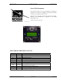
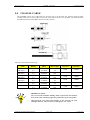
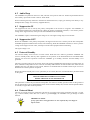
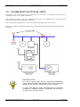
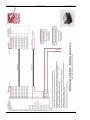
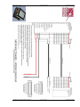
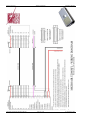
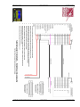
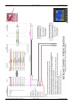
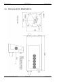
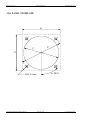
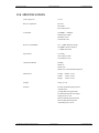
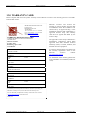
Microair Avionics Pty Ltd
Airport Drive
Bundaberg
Queensland 4670
Australia
Tel: +61 7 41 553048
Fax: +61 7 41 553049
e-mail: [email protected]
Microair Avionics
T2000SFL Transponder
Installation Manual
About This Document
This manual describes the various installation configurations
available for the Microair T2000SFL Transponder, including
connection to a separate altitude encoder.
Microair reserve the right to amend this manual as required,
reflecting any enhancements or upgrades to the T2000
Transponder series.
© Microair Avionics Pty Ltd
DOCUMENT REVISION STATUS
Revision
1.0
1.1
2.0
2.1
2.2
2.3
2.4
2.5
Date
11/02/01
25/05/01
11/07/01
07/11/01
01/06/02
13/08/03
30/10/04
08/04/05
01R3
19/05/06
01R4
01R5
01R6
03/06/06
17/12/06
08/05/07
Change
Initial Draft
Remote display references removed
Part Identification Revision
Deleted SF references
Pin assignments and wiring diagram updated
Coaxial loss data updated
Additional antenna and coax data added
Software upgraded to 05-1.6.4
Software upgraded to 01R1-6-5 software
Amended document references
Additional encoder wiring data added
Multi-Function Display wiring data added
Wiring diagrams updated
T2000SFL Installation Manual 01R6.doc
Page 2 of 24
8th May 2007
Microair Avionics
T2000SFL Transponder
Installation Manual
TABLE OF CONTENTS
1.0
1.1
1.2
INTRODUCTION
4
MOUNTING OPTIONS
INSTALLATION REFERENCES
4
4
2.0
PANEL MOUNTING
5
3.0
MODE C ENCODER
6
4.0
ANTENNA
7
4.1
4.2
MOUNTING
GROUND PLANE
7
7
5.0
COAXIAL CABLE
8
6.0
WIRING
9
6.1
6.2
6.3
6.4
6.5
6.6
GENERAL WIRING
AUDIO BEEP
SUPPRESSION IN
SUPPRESSION OUT
EXTERNAL STANDBY
EXTERNAL IDENT
9
10
10
10
10
10
7.0
CALIBRATION OF INSTALLATION
11
8.0
WIRING DIAGRAMS
12
9.0
INSTALLATION DIMENSIONS
19
10.0 PIN ASSIGNMENTS
20
11.0 PANEL TEMPLATE
21
12.0 SPECIFICATIONS
22
13.0 WARRANTY CARD
23
T2000SFL Installation Manual 01R6.doc
Page 3 of 24
8th May 2007
Microair Avionics
T2000SFL Transponder
Installation Manual
1.0 INTRODUCTION
It would be a really good idea if you read through this section of the manual BEFORE you start installing your
Microair T2000SFL Transponder. If it is too late, and you are reading this message after the fact, perhaps the
information that follows can help you sort things out.
IMPORTANT NOTE
Installation of this transponder should be carried out or inspected by a
qualified installer.
1.1 MOUNTING OPTIONS
The T2000 Transponder series has a number of mounting options. The SFL round face unit can have:
Panel mounting
Remote display mounting
(refer to T2000SFL Remote Display Manual 01R3)
1.2 INSTALLATION REFERENCES
The Microair T2000SFL Transponder should been installed in accordance with the instructions and information
of this manual and FAA AC 43.13-1A Chapter 11.
T2000SFL Installation Manual 01R6.doc
Page 4 of 24
8th May 2007
Microair Avionics
T2000SFL Transponder
Installation Manual
2.0 PANEL MOUNTING
If standard mounting is desired (no remote display unit), determine a suitable location in the instrument panel in
full view of both pilots. Cut a 57mm diameter (2 ¼ inch) hole with 4 x 4mm holes for the mounting screws.
Dimensions for this are provided on the panel template. Allow a minimum of 63mm (2 ½ inch) square, behind
the cut out, to allow clearance from other instruments. A depth of 180mm (7 inches) is recommended to
accommodate the transponder and electrical connectors.
WIRING HARNESS
DB-25 CONNECTOR
NO REAR SUPPORT REQUIRED
50 OHM
COAX
BNC CONNECTOR
M4 MACHINE SCREWS
57MM (2 1/4") INSTRUMENT HOLE
MICROAIR T2000 SFL
PANEL INSTALLATION
The T2000SFL weights only 600g (1 lbs). The four M4 x 12mm machine screws are sufficient to support the
transponder. No rear support is required unless the panel structure itself is too weak to support the load.
IMPORTANT NOTE
Removal of the chassis screws for the purpose of attaching support
bracket is not permitted.
The drilling of holes in the chassis for any purpose is not permitted.
Filings from changing the thread of the M4 screw may cause electrical
faults. Faults of this type are NOT covered by the warranty.
T2000SFL Installation Manual 01R6.doc
Page 5 of 24
8th May 2007
Microair Avionics
T2000SFL Transponder
Installation Manual
3.0 MODE C ENCODER
Mount the mode C blind encoder as per the manufacturer’s installation instructions. All wiring can be run back
to the T2000SFL for connection (refer wiring diagram). The power for the encoder is supplied from the
T2000SFL, and is equal to the aircraft supply voltage. This power is switched when the T2000SFL is turned on.
If the encoder is to be powered separately, it is recommended that the ground wire is run to the T2000SFL, to
ensure correct switching of the data lines.
IMPORTANT NOTE
Most encoder manufacturers advise of a warm up period for their product
before altitude data is supplied. The period can typically be up to 10
minutes.
The T2000SFL software offers the option of leaving the encoder unpowered until mode C operation is selected.
This option is useful for operators using battery power only. A power saving of approx 200mA can be made.
Refer to the PROGRAM MODE item E/C POW (in the T2000SFL User Manual) for this setting.
IMPORTANT NOTE
If the aircraft voltage is 28V and the encoder is 14V only, a 28/14V
converter should be installed between the T2000SFL and the encoder.
Please ensure that the voltage supply line to power the encoder is NOT
shorted to any data line or ground. The T2000SFL will incur internal
faults if a short occurs. This type of damage is NOT covered by the
warranty.
Refer to WIRING DIAGRAMS section for wiring details and pin assignments for commonly used altitude
encoders.
T2000SFL Installation Manual 01R6.doc
Page 6 of 24
8th May 2007
Microair Avionics
T2000SFL Transponder
Installation Manual
4.0 ANTENNA
The T2000SFL requires an antenna tuned to 1090MHz. Microair recommends the use of a TSO’d antenna for
transponder purpose.
4.1 Mounting
The transponder signal is primarily directed to ground stations (Radar sites), hence the antenna is typically
located on the underside of the fuselage. The position should give the antenna a full 360 degree view of the
horizon. The position should be away from other protrusions from the airframe, such as footsteps, and
undercarriage legs.
To avoid possible interference the antenna must be mounted a minimum of 0.3m (12 inches) away from the
T2000SFL. The transponder antenna outputs high level of RF energy, and should be located at least 1m (3ft)
away from vulnerable part of the human body, or be separated by a metal panel.
If the VHF comm. Antenna is already located on the underside of the fuselage, the transponder antenna should
be located at least 1 metre (3ft) away. The transponder antenna should be mounted 2metres (78 inches) from the
DME antenna, 1.5 metres (58 inches) from the ADF sense antenna, and 1metre (39 inches) from TCAS
antennas.
4.2 Ground Plane
In metal skin aircraft the skin forms the ground plane. To ensure a good electrical connection, it may be
necessary to remove paint/primer from the inside face of the skin, before attaching the antenna. This may be
resealed after the antenna is installed. On pressurised aircraft, the antenna should be sealed using RTV-3145 or
equivalent, to seal around the connector and mounting hardware. All antenna mounts should be sealed around
the outside for moisture protection, using RTV-3145 or equivalent.
In a composite aircraft the skin of the airframe cannot be used, and a
suitable ground plane must be fabricated. The ground plane is
typically an aluminium disc with a radius equal to the height of the
antenna (approx. 75mm or 3”). The antenna is mounted in the centre
of the ground plane.
The ground plane does not have to be circular however, but the area
should be approx the same size. Fibreglass aircraft can mount the
ground plane on the inside of the aircraft.
Although carbon fibre is a good reflector of RF, it is not a suit
material for a ground plane. A metal ground plane located outside the
aircraft is ideal.
It is important to ensure that a good electrical contact is established, as
some antennas have sealing O-rings which can isolate this connection.
T2000SFL Installation Manual 01R6.doc
Page 7 of 24
8th May 2007
Microair Avionics
T2000SFL Transponder
Installation Manual
5.0 COAXIAL CABLE
The T2000SFL allows for 1.5dB cable loss from the unit to the antenna. The installer should consider
carefully what type of coaxial cable is to be used, so that this loss limit is not exceeded. The cable should be
terminated with silver plated BNC connectors where possible.
Microair recommends the following:
Cable
RG58/C/U
(Mil Spec)
RG213/A/U
(Mil Spec)
RG223/U
(Mil Spec)
RG400
(Mil Spec)
Belden 8262
URM-43
Bending
Radius
50mm
(2”)
125mm
(5”)
100mm
(4”)
50mm
(2”)
50mm
(2”)
50mm
(2”)
Loss @ 1Ghz
dB/m
0.76dB/m
0.21dB/ft
0.26dB/m
0.08dB/ft
0.47dB/m
0.14dB/ft
0.60dB/m
0.18dB/ft
0.68dB/m
0.21dB/ft
0.47dB/m
0.14dB/ft
Max Length
2.0m
7ft
5.75m
19ft
3.2m
10ft
2.5m
8ft
2.2m
7ft
3.2m
10ft
TX Power
RX
Sensitivity
142W
-70dBm
142W
-70dBm
142W
-70dBm
142W
-70dBm
142W
-70dBm
142W
-70dBm
IMPORTANT NOTE
Do not exceed the minimum bending radius. Tight bends will introduce
losses in the cable, which may affect the performance of the transponder.
When fixing the coax cable in the airframe, do not “strangle” the cable
with tight cable ties. This can distort or damage the coax screen.
T2000SFL Installation Manual 01R6.doc
Page 8 of 24
8th May 2007
Microair Avionics
T2000SFL Transponder
Installation Manual
6.0 WIRING
The T2000SFL must be installed with a wiring harness which meets the following requirements.
6.1 General Wiring
Microair recommends that the encoder be installed and wired in accordance with the manufacturer’s installation
instructions. The encoder can be powered directly from the T2000SFL. The T2000SFL is to be powered from
the aircraft supply, via the avionics master and fuse/circuit breaker with a maximum 5 amp rating (3 amp
minimum).
IMPORTANT NOTE
The aircraft’s electrical system may produce severe transient voltages
during engine start and stop
Microair recommends that the avionics master be turned off during
engine start and stop, to prevent damage occurring to the T2000SFL.
Damage to the transponder as a result of transient voltages is NOT
covered by the warranty.
It is very important to secure all D series plugs via their security screws before operation. Aircraft vibration may
disconnect a D series plug if it not secured. Where possible, wiring is to be run separately to the coaxial cable.
Microair recommends that wiring for all of the T2000SFL’s functions and connections be run at the time of
installation, even though they may not be required at this stage. Adding additional wiring to the loom at a later
stage may be very difficult. All wiring should be installed in accordance with FAA AC43.13-1A Chapter 11 or
equivalent.
Microair recommends the following cable types for connection of the T2000SFL:
Power Input
18 AWG TEFZEL 22759/16-16
Red and Black Wire
External Connections
22 AWG TEFZEL 22759/16-22
22 AWG TEFZEL 27500-22TG1T14
Wire or
Single core shielded
Encoder Power
22 AWG TEFZEL 22759/16-22
Red and Black Wire
Encoder Data
22 AWG TEFZEL 22759/16-22
White Wire
To ensure correct installation and to make future service simple, Microair recommends that all wiring be
labelled for easy identification.
T2000SFL Installation Manual 01R6.doc
Page 9 of 24
8th May 2007
Microair Avionics
T2000SFL Transponder
Installation Manual
6.2 Audio Beep
The T2000SFL beep function when set to ON, will emit a beep tone on this line. Audio beep should be taken to
the Auxiliary input of the aircraft’s radio or Audio Panel.
When connecting the beep function to the Microair M760 transceiver, simply join the beep line directly to any
headphone line (orange wire in factory supplied harness).
6.3 Suppression IN
The suppression IN line is used by the primary transponder in the aircraft to “suppress” the T2000SFL, to
prevent dual transmissions, and interference. When the primary transponder transmits, it will send a positive
voltage to the suppression IN, which prevents the T2000SFL from transmitting.
The T2000SFL requires a minimum signal voltage of 5V. The signal voltage may not exceed 20V.
6.4 Suppression OUT
Where the T2000SFL is the primary transponder, the suppression OUT line is used to prevent other transponder
and DME equipment installed in the aircraft, from interfering. When the T2000SFL transmits, it raises a positive
voltage on the suppression OUT line, which prevents the other equipment from transmitting.
The signal voltage is 5V.
6.5 External Standby
The external standby can be wired to a remote switch. When the line is taken to ground the T2000SFL will
return to standby mode, and stay there regardless of the position of the Selectmode knob. The REM STBY
function can reverse this operation to make the T2000SFL go to standby, when the external standby is not
grounded.
This line is typically taken to an air-switch, which will remain grounded while the airspeed is typically below 30
knots. Hence the transponder will not come out of standby mode until the aircraft has taken off. If the external
Standby Switch is to be taken to an air-switch, Microair recommends that an ON/OFF switch be put in series to
disable the air-switch operation if required.
Where the external standby line is to be operated by an air-switch, Microair recommends that a placard be fitted
on the panel.
AIR-SWITCH FITTED TO EXTERNAL STANDBY
TRANSPONDER WILL REMAIN IN STANDBY
WHILE AIRCRAFT IS ON THE GROUND
(example)
This placard is to advise the pilot that the transponder will remain in standby operation while on the ground. It
may be appropriate to fit an enable/disable switch on the external standby line, between the transponder and the
air-switch, to bypass this mode of operation.
6.6 External Ident
This line is typically wired to a momentary-ON switch, in a position more easily reached by the pilot / co-pilot
(e.g. control column). When this line is taken to ground briefly, the T2000SFL will go through its Ident
function.
IMPORTANT NOTE
If any of the above wiring functions are not required, they can simply be
left not wired.
T2000SFL Installation Manual 01R6.doc
Page 10 of 24
8th May 2007
Microair Avionics
T2000SFL Transponder
Installation Manual
7.0 CALIBRATION OF INSTALLATION
Please refer to the Civil Aviation rules or regulations for your country to determine what the calibration
requirements are, for a transponder installation.
Most countries will require a test of the installation to be carried out by a qualified test centre, along with a
calibration of the encoder and altimeter in the aircraft.
This test is typically repeated every two years, to ensure the ongoing accuracy of the system.
Refer to FAA FAR Part 43 appendix E and F for typical transponder/encoder/altimeter equipment calibration
procedures.
IMPORTANT NOTE
It is vital to aircraft safety that all transponder/encoder/altimeter
systems, which will operate within an SSR system or interact with TCAS
equipped aircraft, perform to a minimum civil aviation standard.
For this reason Microair strongly recommends that all transponder
installations be calibrated at the time of installation, and at periods of
not greater than two years thereafter.
T2000SFL Installation Manual 01R6.doc
Page 11 of 24
8th May 2007
Microair Avionics
T2000 Transponder
Installation Manual
8.0 WIRING DIAGRAMS
T2000SFL with EC2002 Altitude Encoder
T2000SFL with AK-350 Altitude Encoder
T2000SFL with A-30 Altitude Encoder
T2000SFL with Enigma Multi-Function Display
T2000SFL with Dynon D10A Multi-Function Display
T2000SFL Installation Manual 01R6.doc
Page 12 of 24
17th December 2006
Microair Avionics
T2000SFL Installation Manual 01R6.doc
T2000 Transponder
Installation Manual
Page 13 of 24
17th December 2006
Microair Avionics
T2000SFL Installation Manual 01R6.doc
T2000 Transponder
Installation Manual
Page 14 of 24
17th December 2006
Microair Avionics
T2000SFL Installation Manual 01R6.doc
T2000 Transponder
Installation Manual
Page 15 of 24
17th December 2006
Microair Avionics
T2000SFL Installation Manual 01R6.doc
T2000 Transponder
Installation Manual
Page 16 of 24
17th December 2006
Microair Avionics
T2000SFL Installation Manual 01R6.doc
T2000 Transponder
Installation Manual
Page 17 of 24
17th December 2006
Microair Avionics
T2000SFL Installation Manual 01R6.doc
T2000 Transponder
Installation Manual
Page 18 of 24
17th December 2006
Microair Avionics
T2000 Transponder
Installation Manual
9.0 INSTALLATION DIMENSIONS
T2000SFL Installation Manual 01R6.doc
Page 19 of 24
17th December 2006
Microair Avionics
T2000 Transponder
Installation Manual
10.0 PIN ASSIGNMENTS
Pin
1
2
3
4
5
6
7
8
9
10
11
12
13
14
15
16
17
18
19
20
21
22
23
24
25
T2000SFL Installation Manual 01R6.doc
Assignment
BEEP AUDIO TONE
ENCODER SWITCHED POWER OUT (= A/C POWER)
GROUND
NOT WIRED
NOT WIRED
NOT WIRED
NOT WIRED
SUPPRESSION IN (5 TO 20V)
GILLHAM CODE A1
GILLHAM CODE A2
GILLHAM CODE A4
GILLHAM CODE B1
GILLHAM CODE B2
SUPPRESSION OUT (5V)
EXTERNAL STANDBY (GROUND TO OPERATE)
EXTERNAL IDENT (GROUND TO OPERATE)
GILLHAM CODE B4
GILLHAM CODE C1
GILLHAM CODE C2
GILLHAM CODE C4
GILLHAM CODE D4
A/C GROUND
A/C GROUND
A/C POWER (+10V TO +33V)
A/C POWER (+10V TO +33V)
Page 20 of 24
17th December 2006
Microair Avionics
T2000 Transponder
Installation Manual
11.0 PANEL TEMPLATE
61
67
61
57
45 DEG
DIA 4.5mm
T2000SFL Installation Manual 01R6.doc
Page 21 of 24
17th December 2006
Microair Avionics
T2000 Transponder
Installation Manual
12.0 SPECIFICATIONS
ATSO Approval
1C74c
RTCA Compliance
DO-144
DO-160D
DO-178B Level C
Transmitter
1090MHz +/-0.2MHz
200W Pulse Output
80nS Rise Time
120nS Fall Time
Receiver (1030MHz)
0 to –71dBm Dynamic Range
1030MHz Centre Frequency
+/-5MHz Pass band
Input Power
10-33Vdc
100-150mA @ 28V
150-200mA @ 14V
Operational Modes
Standby
Mode 3A
Mode 3A/C
Mode 3A/C with Altitude Displayed
Dimensions
Length 169mm (6.65”)
Width
61mm (2.40”)
Height 61mm (2.40”)
Weight
600g (21 oz)
Features
Encoder Altitude Display Option
Altitude Alert
Voltage Monitoring and Alert
Switched Encoder Power Output
Suppression In / Out
Remote Standby Switch Option
Remote Ident Switch Option
Audio Beep Alert Tone
T2000SFL Installation Manual 01R6.doc
Page 22 of 24
17th December 2006
Microair Avionics
T2000 Transponder
Installation Manual
13.0 WARRANTY CARD
Please complete and return the yellow warranty card to Microair Avionics. The warranty period is 12 months
from the date of sale.
MICROAIR AVIONICS PTY LTD
P O Box 5532
Bundaberg QLD 4670
AUSTRALIA
Tel 07-41553048 INT ++61 7 41553048
Fax 07-41553049 INT ++61 7 41553049
Email [email protected]
Web Site www.microair.com.au
WARRANTY REGISTRATION CARD
Complete the details on this form and return to
our head office.
Microair Avionics
P O Box 5532
Bundaberg QLD 4670
AUSTRALIA
An approved avionics shop is defined as a
maintenance organisation which holds
approvals from their National Aviation
Authority (NAA) to install, calibrate, and
maintain avionics equipment.
If you have misplaced the card, please use
the warranty registration form on the
Microair
Avionics
website
www.microair.com.au.
OWNER’S NAME
ADDRESS
CITY
ZIP
Microair Avionics will honour the
warranty as twelve months from the date
of installation where the installation was
carried out by an approved shop, or the
installation inspected and calibrated by a
approved avionics shop. The warranty
card must be signed and dated by the
avionics shop.
For full details of the warranty please refer
to the T2000SFL User Manual (inside rear
cover).
STATE
COUNTRY
MODEL NO
NUMBER
SERIAL
DATE OF PURCHASE
SUPPLIER
ADDRESS
CITY
ZIP
STATE
COUNTRY
To validate your warranty and assist Microair Avionics in providing you
with better warranty service, fill in and return this warranty card.
You can alternately complete this warranty card on line at our web site
(www.microair.com.au), and email it to us.
Thank you.
T2000SFL Installation Manual 01R6.doc
Page 23 of 24
17th December 2006