1
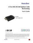
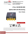
 Dual‐Output SDI/HD‐SDI Video Pattern Generator User Manual (VPG‐SDI) All information is subject to change without notice. All names & trademarks are property of their respective owners. Rev.0911 Made in Taiwan Safety and Notice
The VPG‐SDI Dual‐Output SDI/HD‐SDI Video Pattern Generator has been tested for conformance to safety regulations and requirements, and has been certified for international use. However, like all electronic equipments, the VPG‐SDI should be used with care. Please read and follow the safety instructions to protect yourself from possible injury and to minimize the risk of damage to the unit. z Follow all instructions and warnings marked on this unit. z Do not touch z Do not attempt to service this unit yourself, except where explained in this manual. z Provide proper ventilation and air circulation and do not use near water. z Keep objects that might damage the device and install the unit on a stable surface. z Use only the power adapter and power cords and connection cables designed for this unit. z Do not use liquid or aerosol cleaners to clean this unit. Unplug the power before cleaning. Table of Contents ◇ Introduction …………….………………….………………………….. p.2
◇ Panel Description ………………………………………….…………… p.5
◇ Notice ……………………………………………………………………… p.6
◇ Appendix ………………………………………………………………….. p.6
1
Introduction
The VPG‐SDI Dual‐Output SDI/HD‐SDI Video Pattern Generator is an advanced SDI pattern generator with multi‐format (HD/SD) and multi‐pattern support. Besides still and moving video test patterns, other features such as audio (SMPTE‐291M) are also provided. VPG‐SDI can support up to 8 channel AES compliant audio with 48KHz sample rate. Another attractive feature of VPG‐SDI comes from bypassing HDMI input and allows users with more testing patterns for connected display or treats VPG‐SDI as an advanced HDMI to SDI converter. With portable size, VPG‐SDI is equipped four buttons and LCM screen to ease the control. This device provides a cost effective way to calibrate and test SDI enable video devices and displays. Features z Supported output resolution NTSC 525@60, PAL 625@50, [email protected], 720p@24, 720p@25, [email protected], 720p@30, 720p@50,[email protected], 720p@60, 1080i@50, [email protected], 1080i@60, [email protected], 1080p@24, 1080p@25, [email protected], 1080p@30 Bit Rate: 1.485 Gbps, 1.4835 Gbps, 270 Mbps Resolution: 10bit z Video Patterns 100% Color Bars, Borderline, Random Noise, Check Field, Black, Vertical Lines, Black / White alternate fields, Full Grey / Full White, Black to White Gradient, Random Generator for all still patterns, moving squares White noise, Inverse effect with still pattern, Scrolling Title (see Appendix for illustrations) z Save Settings to Memory Option z ANC Data: EDH (RP‐165), SMPTE 352M, SMPTE291M z Control: LCM & Panel Buttons z Video Output: Dual SDI Output 2
Specifications & Package Contents Technical Role of usage SDI standards Auto SDI rate detection VPG‐SDI
Pattern generator SDI / HD‐SDI Yes SMPTE 259M (270Mbps & 360Mbps) SMPTE 292M / HDTV (1.485Gbps & 1.485 / 1.001Gbps) Supported protocols Video bandwidth Data rates 1.485Gbps
143 / 270 / 1483 / 1485 Mbps
[HD] 720p50/59.94/60, 1080p24/30, 1035i50/59.94/60, 1080i50/59.94/60 Video support [SD] [email protected], PAL@50Hz SDI signal type SMPTE‐292M, SMPTE‐259M HDMI bypass Yes
Output impedance 75Ω Cable equalization / [HD‐SDI] up to 150m (500ft)
transmission [SD‐SDI] up to 300m (1000ft) Audio support Yes PCB Stack‐up 4‐layer board [impedance control — differential 100Ω; single 50Ω] Input None
Output 2x BNC [SDI] BNC connector 75Ω interlocking socket HDMI connector Type A [19‐pin female]
Amplitude: Within 800mV <10% Long time jitter <1.0μ [HD] Eye pattern Timing jitter <1.0μ Rise overshoot: Less than 2% characteristics Fall overshoot: Less than 2% Alignment jitter <0.2μ Mechanical VPG‐SDI Housing Metal enclosure Model 160 x 110 x 20mm [6.3” x 4.3” x 0.8”] Dimensions Package 330 x 200 x 95mm [1’1” x 7.9” x 3.7”] [L x W x H] Carton 495 x 440 x 380mm [1’7” x 1’5” x 1’3”] Model 325g [11oz] Weight Package g [ lbs] Fixedness Interlocking power supply Power supply 5V 4A DC
Power consumption 10 Watts [max]
Operation temperature 0~40°C [32~104°F] Storage temperature ‐20~60°C [‐4~140°F] Relative humidity 20~90% RH [no condensation] 1x VPG‐SDI
Package Contents 1x 5V power supply unit 1x User manual The measurement results are from Tektronix WFM‐7120 with SDI through 1m (3.3ft) long Belden 1694A. 3
Menu Operation
Menu Items 01 Format Resolution Frequency 02 Video 03 Audio 04 Motion 05 ANC Data 06 System NTSC / PAL / 720p / 1080p / 1080i 60Hz / 59.94Hz / 50Hz / 30Hz
29.97Hz / 25Hz / 24Hz / 23.98Hz Output YCbCr 4:2:2
Patterns SMPTE Bar / 100% Bar
Check Field 1 / Check Field 2 / Check Field 3 Gradient R1 / Gradient G1 / Gradient B1 Gradient R2 / Gradient G2 / Gradient B2 Gradient R3 / Gradient G3 / Gradient B3 Gradient R4 / Gradient G4 / Gradient B4 Red Level 1 / Red Level 2 Green Level 1 / Green Level 2 Blue Level 1 / Blue Level 2 100% Red / 100% Green / 100% Blue 100% White / 70% Gray / 40% Gray / Black Noise / Circle 1 / Circle 2 / Moire H Stripe R / H Stripe G / H Stripe B V Stripe R / V Stripe G / V Stripe B Chess 1 / Chess 2 / Sequence
Text Off / On‐White / On‐Black
Timer Off / On‐W/B / On‐B/W
Mode Off / On
Group 1+2 / 3+4
Level ‐6dB / ‐12dB / ‐18dB / ‐24dB
‐30dB / ‐36dB / ‐42dB / Silence / Random Off / CH 1234 / CH 1 / CH 2 / CH 3 / CH 4
Mask CH 1+2 / CH 3+4 Motion No Motion / Square 1 / Square 2
2 Squares / Square Inv Data Speed 1 / 2 / 3 / 4 / 5 / 6 / 7 / 8 SMPTE‐352M Off / On
EDH On / Off
Status No Change / Factory / Now Save
Version V1.00
4
Panel Description
Top View Button
Menu Enter Up Down Function
Trigger the menu operation
Enter the menu item
Choose the last menu item Choose the next menu item Side View 1 2 3
1. SDI OUTPUT A: Connect to a SDI device for SDI or HD‐SDI signal output either from the chosen pattern or the converted HDMI source signal 2. Lock LED: showing if the audio/video signal existed or not 3. SDI OUTPUT B: Connect to a SDI device for SDI or HD‐SDI signal output either from the chosen pattern or the converted HDMI source signal 4 5
4. HDMI INPUT: Plug in a HDMI cable to be linked to a HDMI source 5. +5V DC: Connect to a 5V DC power supply unit 5
Appendix
Notice
In HDMI bypass mode, users must be aware of that the jitters coming from HDMI sources, such as DVD players, may be much higher than typical requirement according to SMPTE request on HD‐SDI signals. This will result in SDI output with high jitters or even no SDI outputs! Appendix
z Data Identification Word of Ancillary Data Packet ANC Data DID
352M 0x41
RP‐165‐EDH* 0xF4
* Data Type 1(SMPTE‐291M) z Built‐in Video Patterns SDID/DBN
0x01
0x00
6
7