1
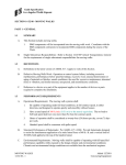
T55510 / T55511
Easy Lift Stand
Doughty Engineering Ltd
Operating Manual
www.doughty-engineering.co.uk
Table of Contents
Revision History ............................................................................................................................... 2
Contact Details ................................................................................................................................. 2
Purpose ............................................................................................................................................. 3
Safety Inspection.............................................................................................................................. 3
Setting Up.......................................................................................................................................... 3
Loading the stand ............................................................................................................................ 3
Height Adjustment ........................................................................................................................... 4
Servicing & Maintenance................................................................................................................. 4
Illustrations ....................................................................................................................................... 5
Declaration of Conformity ............................................................................................................... 6
Revision History
Issue
1
2
3
4
5
Amendment
New document
Figure 3 added
Servicing and maintenance section added
Cover page added & format revised
T55511 added to cover page
Date
04-03-08
26-03-08
15-04-08
22-04-08
16-05-08
Contact Details
Doughty Engineering Ltd
Crow Arch Lane
Ringwood
Hants
BH24 1NZ
England
Telephone +44 (0) 1425 478961
Fax +44 (0) 1425 474481
www.doughty-engineering.co.uk
[email protected]
www.doughty-engineering.co.uk
Page 2 of 6
Issue: 05
Date: 16-05-08
User Manual for the Easy Lift Stand
Part No: T55510 – Chrome Finish
Part No: T55511 – Black Finish
Purpose
The Easy Lift stand is designed to support lighting fixtures for stage, film, photograph and
broadcast productions on location or in the studio.
Safety Inspection
1. Maximum load: 30Kg
2. The stand should only be set up on a horizontal level surface.
3. The stand must be set up on firm ground capable of taking both the weight of the stand
and its load without sinking in.
4. All loads should be balanced when using a T bar.
5. For use in open air secure stand with safety cables attached to loop A (fig. 3)
6. Periodically check that the two steel cables inside that raise and lower the telescopic
centre column (via inspection holes in the first centre pole riser) are in good condition. In
the event that a cable is frayed or slack (with stand loaded and knobs C & D, fig. 1,
loosened), stop using the stand and send it to your dealer for repair.
Setting Up
1. Verify that the lower base is open by pushing the stand brace to the bottom position and
locking it with locking screw H (fig 4). This operation is easier with the stand column
folded.
2. The stand incorporates one adjustable leg to compensate for differences in ground level
• Loosen locking screw B (fig. 1)
• Extend the leg until the stand reaches the vertical position
• Tighten locking screw B.
3. It is essential that the stand is levelled BEFORE loading with equipment.
Loading the stand
1. Open the locking screw E (fig. 1) before inserting the spotlight spigot into the 28mm socket
at the top of the stand.
2. Secure in position by tightening the locking screw E.
3. Only use the stand for supporting large luminaries on location in conjunction with the
safety cable, as the stand could tip over in windy conditions. It is recommended that you
use the 28mm female socket for heavy loads as it provides more stability.
www.doughty-engineering.co.uk
Page 3 of 6
Issue: 05
Date: 16-05-08
Height Adjustment
Before adjusting the height, check the following:
• Is the stand set up correctly, and has the condition of the ground been taken into
account?
• Are the spotlights or arms correctly balanced and locked (screw E)?
• Loosen the two locking screws C and D (fig. 1) by turning anti-clockwise.
To release crank J, refer to fig. 2, and proceed as follows:
• Loosen screw F turning clockwise
• Tip the crank downwards
• Tighten screw F turning it anti-clockwise to ensure the crank handle is locked into the
operational position.
Turn the crank handle J clockwise to raise the columns.
When the desired height has been achieved, lock screws C and D (fig. 1) by turning them
clockwise. The foot rest G (fig. 4) can be useful here. Do not forget to secure the stand with
safety cables on location, attached to loop A (fig. 3).
In the event that the telescopic centre column descends when loaded but without setting into
action the crank handle, adjust the brakes by tightening the screw K (fig. 1) clockwise until the
column remains in position with equipment loaded, and knobs C and D loosened.
If problems arise when cranking, check the following:
• Have screws C and D been loosened?
• Is the load on the stand too heavy (max. 30Kg)?
• Is there any sign of damage to the stand (ie. Caused during transportation)?
• Is the height adjustment being restricted by a branch, ceiling, or balustrades etc.
• Have any of the safety cables (where fitted) not been released?
Servicing & Maintenance
Servicing and maintenance must be carried out by approved personnel. To find your nearest
approved service agent, please contact Doughty Engineering Limited.
Servicing carried out by non approved agents, or the use of non approved spares will
invalidate certification.
www.doughty-engineering.co.uk
Page 4 of 6
Issue: 05
Date: 16-05-08
Illustrations
Figure 1
E
Figure 2
D
K
F
C
J
B
G
A
H
Figure 3
Figure 4
www.doughty-engineering.co.uk
Page 5 of 6
Issue: 05
Date: 16-05-08
Declaration of Conformity
www.doughty-engineering.co.uk
Page 6 of 6
Issue: 05
Date: 16-05-08