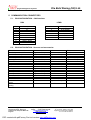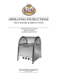
1
Engine Management Systems
Ole Buhl Racing (UK) Ltd.
SUBJECT:
Euro 1 User Manual
AUTHORS:
C. Galletti, O. Buhl and R.O’Hagan
VERSION:
Euro 1 – 430
Ole Buhl Racing (UK) Ltd.
Roughwood House, Highwood
Nr Ringwood, Hampshire BH24 3LE
England
Telephone : (+44) (0)1425 47 88 22
Telefax
: (+44) (0)1425 47 88 66
[email protected]
www.efitech.co.uk
Registered Office: Windover House
St. Ann Street, Salisbury SP1 2DR
Registered in England No.:3635953
V.A.T. Nr. GB 722 5686 27
PDF created with pdfFactory Pro trial version www.pdffactory.com
Engine Management Systems
1.
Ole Buhl Racing (UK) Ltd.
ABBREVIATIONS AND SYMBOLS ------------------------------------------------------------- 7
2.1. General -------------------------------------------------------------------------------------------------------------------------8
2.1.1. CAN Interface------------------------------------------------------------------------------------------------------------8
2.1.2. AMC - active mapping controller------------------------------------------------------------------------------------8
2.1.3. Dashboard and Datalogger -------------------------------------------------------------------------------------------9
2.2. System Set-up ---------------------------------------------------------------------------------------------------------------9
2.2.1. Measuring crankshaft position (ANTAV) --------------------------------------------------------------------------9
3.
SOFTWARE DESCRIPTION --------------------------------------------------------------------- 11
3.1. Boost control ----------------------------------------------------------------------------------------------------------- 11
3.1.1. Boost control valve fully open below target pressure offset------------------------------------------------ 11
3.1.2. Proportional correction enabled within percentage of sensor range ---------------------------------- 11
3.1.3. Proportional DC step relative to base duty cycle per 100mbar pressure error --------------------- 12
3.1.5. Closed loop integral control within target boost pressure offset --------------------------------------- 12
3.1.6. Integral step of waste gate duty cycle regulation
--------------------------------------------------------- 13
3.1.7. Maximum integral duty cycle correction
-------------------------------------------------------------------- 13
3.1.8. Boost control valve piloting frequency
---------------------------------------------------------------------- 13
3.1.9. Open loop waste gate valve duty cycle ---------------------------------------------------------------------- 13
3.1.10. Target boost pressure f(RPM)
------------------------------------------------------------------------------- 13
3.1.11. Decrease abs waste gate boost pressure f(WATER TEMP)
----------------------------------------- 13
3.1.12. Decrease abs waste gate boost pressure f(AIR TEMP) ------------------------------------------------ 13
3.2. Car speed----------------------------------------------------------------------------------------------------------------- 14
3.2.1. Circumference of wheel
----------------------------------------------------------------------------------------- 14
3.2.2. Number of pulses each wheel ------------------------------------------------------------------------------------- 14
3.3. Cranking ------------------------------------------------------------------------------------------------------------------ 15
3.3.1. Prime (grouped) injection pulse width on first crank pulse
--------------------------------------------- 15
3.3.2. Switch from Crank to Run mode above RPM threshold
----------------------------------------------- 15
3.3.3. Switch from Run to Crank mode below RPM threshold ------------------------------------------------- 15
3.3.4. Cranking fuel injection multiplication----------------------------------------------------------------------------- 15
3.4. Diagnostics -------------------------------------------------------------------------------------------------------------- 16
3.4.1. Diagnostic channel configuration:--------------------------------------------------------------------------------- 16
3.4.2. Channel 1: Ignition retardation------------------------------------------------------------------------------------- 16
3.4.3. Channel 2: RPM Over rev ------------------------------------------------------------------------------------------ 16
3.4.4. Channel 2: MAP sensor error -------------------------------------------------------------------------------------- 16
3.4.5. Channel 3: Throttle potentiometer error------------------------------------------------------------------------- 16
3.4.6. Channel 4: Battery voltage error ---------------------------------------------------------------------------------- 16
3.4.7. Channel 5: Water temperature sensor error ------------------------------------------------------------------- 17
3.4.8. Channel 6: Air temperature sensor error ------------------------------------------------------------------------ 17
3.4.9. Channel 7: Open loop lambda sensor error -------------------------------------------------------------------- 17
3.4.10. Channel 18: Oil pressure sensor error ------------------------------------------------------------------------- 17
3.5. Digital Input – Configuration -------------------------------------------------------------------------------------- 18
3.5.1. Kill Switch --------------------------------------------------------------------------------------------------------------- 18
3.5.2. Injection / ignition trim switch -------------------------------------------------------------------------------------- 18
3.5.3. Launch Control -------------------------------------------------------------------------------------------------------- 18
Ole Buhl Racing (UK) Ltd.
Roughwood House, Highwood
Nr Ringwood, Hampshire BH24 3LE
England
Telephone : (+44) (0)1425 47 88 22
Telefax
: (+44) (0)1425 47 88 66
[email protected]
www.efitech.co.uk
Registered Office: Windover House
St. Ann Street, Salisbury SP1 2DR
Registered in England No.:3635953
V.A.T. Nr. GB 722 5686 27
PDF created with pdfFactory Pro trial version www.pdffactory.com
Engine Management Systems
Ole Buhl Racing (UK) Ltd.
3.5.4. Power Shift ------------------------------------------------------------------------------------------------------------- 18
3.5.5. Air condition switch --------------------------------------------------------------------------------------------------- 18
3.6. Digital Input ‘Air Condition’ --------------------------------------------------------------------------------------- 19
3.6.1. Switch Polarity --------------------------------------------------------------------------------------------------------- 19
3.7. Digital Input “INJ / IGN Trim by Switch” ---------------------------------------------------------------------- 19
3.7.1. Switch Polarity --------------------------------------------------------------------------------------------------------- 19
3.8. Digital Input ‘Kill Switch’-------------------------------------------------------------------------------------------- 19
3.8.1. Switch polarity --------------------------------------------------------------------------------------------------------- 19
3.8.2. Kill switch activation delay------------------------------------------------------------------------------------------ 19
3.9. Digital Input ‘Launch Control’ ------------------------------------------------------------------------------------ 19
3.9.1. Switch Polarity --------------------------------------------------------------------------------------------------------- 19
3.9.2. Launch Control Limiter (fuel cut)
----------------------------------------------------------------------------- 19
3.10.
Digital Input ‘Power shift’ ---------------------------------------------------------------------------------------- 19
3.10.1. Switch Polarity ------------------------------------------------------------------------------------------------------- 19
3.11.
Drive By Wire--------------------------------------------------------------------------------------------------------- 20
3.11.1. Drive by wire---------------------------------------------------------------------------------------------------------- 20
3.11.2. Desired TPS Target f(PPSA)------------------------------------------------------------------------------------- 20
3.12.
Fuel – cut-off (FCO) ----------------------------------------------------------------------------------------------- 21
3.12.1. FCO activated if RPM exceeds upper threshold
-------------------------------------------------------- 21
3.12.2. Lower RPM limit exit fuel cut-off
---------------------------------------------------------------------------- 21
3.12.3. FCO activated if throttle position is below threshold
--------------------------------------------------- 21
3.12.4. Mixture enrichment when FCO is de-activated -------------------------------------------------------------- 21
3.12.5. Injection enrichment active in number of engine cycles--------------------------------------------------- 21
3.13.
Fuel – Limits---------------------------------------------------------------------------------------------------------- 22
3.13.1. Maximum Injection time
--------------------------------------------------------------------------------------- 22
3.13.2. Minimum Injection time ---------------------------------------------------------------------------------------- 23
3.13.3. Water temperature threshold (TH20WA) cancels warmup phase -------------------------------------- 23
3.13.4. Cancel warmup phase if water temperature exceeds threshold ----------------------------------------- 23
3.14.
Fuel – Main Maps --------------------------------------------------------------------------------------------------- 24
3.14.1. Injection phase (in steps of 90 degrees)
------------------------------------------------------------------ 24
3.14.2. Fuel Injection trim by switch ---------------------------------------------------------------------------------- 24
3.14.3. Fuel injection correction f(MAP) ----------------------------------------------------------------------------- 25
3.14.4. Fuel injection correction f(WATER TEMP)
--------------------------------------------------------------- 25
3.14.5. Fuel injection correction f(AIR TEMP)
--------------------------------------------------------------------- 25
3.14.6. Fuel injection correction f(BARO PRESS) ---------------------------------------------------------------- 25
3.14.7. Battery Voltage injector offset f(VBATT)
------------------------------------------------------------------ 25
3.14.8. Fuel injection map
---------------------------------------------------------------------------------------------- 26
3.14.9. Fuel Injection multiplication factor during warm-up f (TH20)--------------------------------------------- 26
3.14.10. Fuel injection correction f(TPS)
--------------------------------------------------------------------------- 26
3.14.11. Fuel Injection correction f (THROT) if RPM < Crank-to-Run threshold. ----------------------------- 26
3.14.12. Fuel Injection correction on cylinders 2+3 f(THROTTLE)
------------------------------------------- 26
3.15.
Idle speed ------------------------------------------------------------------------------------------------------------- 27
3.15.1. Spark advance offset it air condition switch is ON
----------------------------------------------------- 28
3.15.2. Idle condition set within RPM offset to target idle speed ---------------------------------------------- 28
3.15.3. Idle speed condition enabled below Throttle position
-------------------------------------------------- 28
Ole Buhl Racing (UK) Ltd.
Roughwood House, Highwood
Nr Ringwood, Hampshire BH24 3LE
England
Telephone : (+44) (0)1425 47 88 22
Telefax
: (+44) (0)1425 47 88 66
[email protected]
www.efitech.co.uk
Registered Office: Windover House
St. Ann Street, Salisbury SP1 2DR
Registered in England No.:3635953
V.A.T. Nr. GB 722 5686 27
PDF created with pdfFactory Pro trial version www.pdffactory.com
Engine Management Systems
Ole Buhl Racing (UK) Ltd.
3.15.4. Time interval between integral corrections
--------------------------------------------------------------- 28
3.15.5. Negative integral duty cycle correction cancelled above threshold------------------------------------- 28
3.15.6. Initial idle duty cycle correction timer (TIMAC1) if Switch 2 = ON -------------------------------------- 28
3.15.7. Initial idle duty cycle Correction if Switch 2 = ON
----------------------------------------------------- 29
3.15.8. Idle duty cycle correction if switch 2 = ON after TIMAC1 interval -------------------------------------- 29
3.15.9. Idle air valve duty cycle frequency
------------------------------------------------------------------------- 29
3.15.10. Maximum positive duty cycle integral regulation
------------------------------------------------------ 29
3.15.11. Minimum negative duty cycle integral regulation ------------------------------------------------------ 29
3.15.12. Maximum actuated idle speed duty cycle
--------------------------------------------------------------- 29
3.15.13. Minimum actuated idle speed duty cycle ----------------------------------------------------------------- 29
3.15.14. Stepper motor: 1 = Two Phase; 2 = Four Phase---------------------------------------------------------- 29
3.15.15. Total stroke of stepper motor ----------------------------------------------------------------------------------- 29
3.15.16. Idle speed spark advance correction f(RPM-TARGET)-------------------------------------------------- 29
3.15.17. Idle speed duty cycle correction f(VBATT) -------------------------------------------------------------- 30
3.15.18. Idle speed duty cycle correction f(AIR TEMP)
--------------------------------------------------------- 30
3.15.19. Proportional correction of idle speed duty cycle f(RPM-TARGET)------------------------------------ 30
3.15.20. Integral idle speed duty cycle gain f(RPM-TARGET)----------------------------------------------------- 30
3.15.21. Open loop idle valve duty cycle f(TH20.CRANKING) ---------------------------------------------------- 30
3.15.22. Target Idle engine speed f(TH20)
----------------------------------------------------------------------- 30
3.15.23. Spark advance in idle speed condition f(TH20)------------------------------------------------------------ 31
3.16.
Lambda Auto Mapping-------------------------------------------------------------------------------------------- 32
3.16.1. Closed loop lambda Learn ---------------------------------------------------------------------------------------- 32
3.16.2. Active if throttle position exceeds limit
-------------------------------------------------------------------- 32
3.16.3. Active if engine speed exceeds limit
----------------------------------------------------------------------- 32
3.16.4. Active if water temperature exceeds limit ----------------------------------------------------------------- 32
3.16.5. Active if d(tps%) transient is less than
--------------------------------------------------------------------- 32
3.16.6. Maximum lambda to target error
---------------------------------------------------------------------------- 32
3.16.7. Activate within RPM breakpoint offset
--------------------------------------------------------------------- 32
3.16.8. Active within TPS breakpoint offset
------------------------------------------------------------------------ 33
3.16.9. Integral fuel correction step
---------------------------------------------------------------------------------- 33
3.16.10. Maximum allowed fuel mixture correction
------------------------------------------------------------- 33
3.16.11. Target lambda value f(RPM.THR) ---------------------------------------------------------------------------- 33
3.16.12. Lambda Control ---------------------------------------------------------------------------------------------------- 33
3.17.
Lambda Calibration ------------------------------------------------------------------------------------------------ 34
3.17.1. Lambda control ------------------------------------------------------------------------------------------------------ 34
3.17.2. Lean mixture below sensor output voltage
--------------------------------------------------------------- 34
3.17.3. Rich mixture above sensor output voltage
--------------------------------------------------------------- 34
3.17.4. Maximum enrichment of fuel mixture -------------------------------------------------------------------------- 34
3.17.5. Maximum lean-out of fuel mixture ------------------------------------------------------------------------------ 35
3.17.6. Closed loop mixture correction enabled if air temperature exceeds ----------------------------------- 35
3.17.7. Closed loop mixture correction disabled if d(TPS) exceeds---------------------------------------------- 35
3.17.8. High water temperature threshold for closed loop activation--------------------------------------------- 35
3.17.9. Low water temperature threshold for closed loop activation --------------------------------------------- 35
3.17.10. Timer 1: Delay activation of CLC if water temp is below low threshold------------------------------ 35
3.17.11. Timer 2: Delay activation of CLC if water temp is between thresholds ------------------------------ 35
3.17.12. Timer 3: Delay activation of CLC if water temp exceeds high threshold ---------------------------- 35
3.17.13. Open loop lambda control map -------------------------------------------------------------------------------- 35
3.17.14. Time interval between integral fuel corrections -------------------------------------------------------- 36
3.17.15. Proportional fuel correction step first time lean ------------------------------------------------------------ 36
3.17.16. Proportional fuel correction step first time rich ------------------------------------------------------------- 36
3.18.
Lambda calibration – self learn (Standard Lambda sensor only) ---------------------------------- 37
3.18.1. Water temperature threshold activates self learn strategy
------------------------------------------ 37
3.18.2. Throttle position threshold activates self learn strategy
---------------------------------------------- 37
Ole Buhl Racing (UK) Ltd.
Roughwood House, Highwood
Nr Ringwood, Hampshire BH24 3LE
England
Telephone : (+44) (0)1425 47 88 22
Telefax
: (+44) (0)1425 47 88 66
[email protected]
www.efitech.co.uk
Registered Office: Windover House
St. Ann Street, Salisbury SP1 2DR
Registered in England No.:3635953
V.A.T. Nr. GB 722 5686 27
PDF created with pdfFactory Pro trial version www.pdffactory.com
Engine Management Systems
Ole Buhl Racing (UK) Ltd.
3.18.3. RPM threshold activates self learn strategy
-------------------------------------------------------------- 37
3.18.4. Delay to activate self learn
----------------------------------------------------------------------------------- 37
3.18.5. Duration of self learn calculation
---------------------------------------------------------------------------- 37
3.18.6. Time interval between integral correction steps --------------------------------------------------------- 37
3.18.7. Self-learning weighting diagram --------------------------------------------------------------------------------- 38
3.19.
Power Shift------------------------------------------------------------------------------------------------------------ 39
3.19.1. Power shift cut time (ignition)
------------------------------------------------------------------------------- 39
3.19.2. Power shift reset time
----------------------------------------------------------------------------------------- 39
3.20.
Programmable output configuration------------------------------------------------------------------------- 40
3.20.1. Idle Output ------------------------------------------------------------------------------------------------------------ 40
3.20.2. Boost Output---------------------------------------------------------------------------------------------------------- 40
3.20.3. Warning Light -------------------------------------------------------------------------------------------------------- 40
3.20.4. Universal Output----------------------------------------------------------------------------------------------------- 40
3.20.5. Shift Light-------------------------------------------------------------------------------------------------------------- 40
3.20.6. Power Latch----------------------------------------------------------------------------------------------------------- 40
3.21.
RPM limiter------------------------------------------------------------------------------------------------------------ 41
3.21.1. Fuel hard cut above engine speed threshold
----------------------------------------------------------- 41
3.21.2. Ignition soft cut above engine speed threshold
--------------------------------------------------------- 41
3.21.3. RPM offset for ignition hard cut
----------------------------------------------------------------------------- 41
3.22.
Sensor Calibration ------------------------------------------------------------------------------------------------- 42
3.22.1. Maximum absolute manifold air pressure at 5 volts sensor signal-------------------------------------- 42
3.22.2. Minimum absolute manifold air pressure at 0 volts sensor signal -------------------------------------- 42
3.22.3. Maximum absolute auxiliary pressure at 5 volts sensor signal ------------------------------------------ 43
3.22.4. Maximum absolute auxiliary pressure at 0 volts sensor signal ------------------------------------------ 43
3.22.5. Maximum Oil pressure at 5 volts sensor signal
-------------------------------------------------------- 43
3.22.6. Minimum oil pressure at 0 volts sensor signal
---------------------------------------------------------- 43
3.22.7. Air temperature linearization table
------------------------------------------------------------------------- 43
3.22.8. Water temperature linearization table
-------------------------------------------------------------------- 43
3.22.9. Linearization lambda sensor ‘LINEAR’------------------------------------------------------------------------- 44
3.23.
Shift Lights ----------------------------------------------------------------------------------------------------------- 45
3.23.1. Shift light 0ff→ON if RPM above limit
-------------------------------------------------------------------- 45
3.23.2. Shift light 0ff→ON if RPM below limit
-------------------------------------------------------------------- 45
3.24.
Spark Advance – Main Maps ------------------------------------------------------------------------------------ 46
3.24.1. Spark advance offset f(AIR TEMP)----------------------------------------------------------------------------- 46
3.24.2. Dwell time f(BATT VOLTAGE)
------------------------------------------------------------------------------ 46
3.24.3. Spark Advance in Idle speed condition f(TH20) ------------------------------------------------------------- 46
3.24.4. Spark advance correction f(MAP)------------------------------------------------------------------------------- 46
3.24.5. Spark advance map ------------------------------------------------------------------------------------------------ 46
3.24.6. Spark advance correction on cylinder 1+4 f(RPM.THR) -------------------------------------------------- 47
3.24.7. Spark advance correction on cylinder 2+3 f(RPM.THR) -------------------------------------------------- 47
3.24.8. Idle speed spark advance correction f[RPM.THRS] -------------------------------------------------------- 47
3.25.
Spark Advance - Setting ----------------------------------------------------------------------------------------- 48
3.25.1. Spark advance time delay correction
--------------------------------------------------------------------- 48
3.25.2. Time after start with mapped spark advance
----------------------------------------------------------- 48
3.25.3. If water temperature is <TH2OSA: Offset spark advance ANTACC ---------------------------------- 48
3.25.4. Water temperature threshold (TH20SA) cancels spark advance correction ------------------------- 48
3.25.5. Spark advance offset (ANTACC)
------------------------------------------------------------------------ 48
3.25.6. Spark advance correction by switch ------------------------------------------------------------------------ 48
Ole Buhl Racing (UK) Ltd.
Roughwood House, Highwood
Nr Ringwood, Hampshire BH24 3LE
England
Telephone : (+44) (0)1425 47 88 22
Telefax
: (+44) (0)1425 47 88 66
[email protected]
www.efitech.co.uk
Registered Office: Windover House
St. Ann Street, Salisbury SP1 2DR
Registered in England No.:3635953
V.A.T. Nr. GB 722 5686 27
PDF created with pdfFactory Pro trial version www.pdffactory.com
Engine Management Systems
3.25.7. Spark advance offset if air conditioning is ON
Ole Buhl Racing (UK) Ltd.
------------------------------------------------------ 48
3.26.
System Setup -------------------------------------------------------------------------------------------------------- 49
3.26.1. Maximum RPM for use in tables
-------------------------------------------------------------------------- 49
3.26.2. Minimum RPM for use in tables
--------------------------------------------------------------------------- 49
3.26.3. Crankshaft sensor pulse (cylinder 1) detected ANTAV degrees before TDC ------------------------ 49
3.26.4. Crankshaft pickup position before TDC; only CLIO
-------------------------------------------------- 49
3.26.5. First SMOT detected after missing teeth in 36-1/60-2 before TDC------------------------------------- 49
3.26.6. Crank trigger disc---------------------------------------------------------------------------------------------------- 50
3.26.7. Select MAP sensor-------------------------------------------------------------------------------------------------- 50
3.26.8. Select engine load -------------------------------------------------------------------------------------------------- 50
3.26.9. Select lambda sensor ---------------------------------------------------------------------------------------------- 50
3.26.10. Duration RPM tachometer pulse
------------------------------------------------------------------------- 50
3.26.11. Number of impulses for RPM tachometer each engine revolution------------------------------------ 50
3.27.
System Setup – Data Export ------------------------------------------------------------------------------------ 51
3.27.1. CAN bus data export ----------------------------------------------------------------------------------------------- 51
3.28.
Transient Fuel ------------------------------------------------------------------------------------------------------- 52
3.28.1. Time interval for d(TPS) derivative calculation
-------------------------------------------------------- 52
3.28.2. Maximum d(TPS) derivative value used in calculation
---------------------------------------------- 52
3.28.3. d(TPS) derivative value enable transient fuel ------------------------------------------------------------ 53
3.28.4. Time interval for transient fuel decay calculation -------------------------------------------------------- 53
3.28.5. Scaling factor for d(TPS) derivative calculation --------------------------------------------------------- 53
3.28.6. Transition fuel decay f(RPM) in d(TPS) units ------------------------------------------------------------- 53
3.28.7. Transient fuel correction f(RPM) ----------------------------------------------------------------------------- 53
3.28.8. Transient fuel enrichment multiplier f(TH20) ----------------------------------------------------------------- 53
3.29.
Universal output ---------------------------------------------------------------------------------------------------- 54
3.29.1. Activation delay time from engine start
----------------------------------------------------------------- 54
3.29.2. Enable output if MAP exceeds limit ------------------------------------------------------------------------- 54
3.29.3. Enable output if air temperature exceeds threshold ---------------------------------------------------- 54
3.29.4. Enable output if water temperature exceeds threshold ------------------------------------------------ 54
3.29.5. Enable output if throttle position exceeds threshold ---------------------------------------------------- 54
3.29.6. RPM limit #1 switches output OFF à ON ----------------------------------------------------------------- 54
3.29.7. RPM limit #2 switches output ON à OFF ----------------------------------------------------------------- 54
3.29.8. RPM limit #3 switches output OFF à ON ----------------------------------------------------------------- 54
4.
PIN OUT----------------------------------------------------------------------------------------------- 55
5.
COMMUNICATION CONNECTORS ----------------------------------------------------------- 56
5.1.
PIN CONFIGURATION – CAN Interface------------------------------------------------------------------------- 56
DB9
5.2.
6.
LEMO -------------------------------------------------------------------------------------------------------------- 56
PIN CONFIGURATION - Sensors and accessories --------------------------------------------------------- 56
ERROR RESOLVING ------------------------------------------------------------------------------ 57
Ole Buhl Racing (UK) Ltd.
Roughwood House, Highwood
Nr Ringwood, Hampshire BH24 3LE
England
Telephone : (+44) (0)1425 47 88 22
Telefax
: (+44) (0)1425 47 88 66
[email protected]
www.efitech.co.uk
Registered Office: Windover House
St. Ann Street, Salisbury SP1 2DR
Registered in England No.:3635953
V.A.T. Nr. GB 722 5686 27
PDF created with pdfFactory Pro trial version www.pdffactory.com
Ole Buhl Racing (UK) Ltd.
Engine Management Systems
1. ABBREVIATIONS AND SYMBOLS
A/D
Analogue/Digital converter.
d(TPS)
Throttle position derivative, i.e. rate of change of throttle position.
ECU
Fuel injection / ignition computer - Electronic Control Unit
Editor
The editor allows you to configure your engine map to your specific requirements. It can
be run online with the ECU or a file can be loaded from your hard drive.
In the editor you can configure a large range of engine parameters by adjusting either,
limits, constants, vectors or tables.
ANTAV
Angle in degrees between crank tooth passing directly under the sensor to the point at which
the reference cylinder is in TDC.
DTW
Duty Cycle
SMOT
Crankcount
SCAM
Camshaft Count
SA
Ignition Spark Advance is expressed in crankshaft degrees in respect to TDC.
T90
The time period between 2 pulses SMOT.
TEROG
Fuel injection erogation time. This expresses the basic fuel injection value from the table
corrected with all corrections except the battery voltage correction.
TINJ
Actual opening of the fuel injector:
T90
Time between 2 pulses smot - crank
Ole Buhl Racing (UK) Ltd.
Roughwood House, Highwood
Nr Ringwood, Hampshire BH24 3LE
England
TINJ = TEROG + (Battery Voltage Correction).
Telephone : (+44) (0)1425 47 88 22
Telefax
: (+44) (0)1425 47 88 66
[email protected]
www.efitech.co.uk
Registered Office: Windover House
St. Ann Street, Salisbury SP1 2DR
Registered in England No.:3635953
V.A.T. Nr. GB 722 5686 27
PDF created with pdfFactory Pro trial version www.pdffactory.com
Engine Management Systems
Ole Buhl Racing (UK) Ltd.
2. INTRODUCTION
This document describes the function of the EURO1 engine management system, which adapts easily to a
4 cylinder engine, aspirated as well as turbo charged.
All new EFI Technology engine management systems operate with the benefits from the use of CAN
communication between components. Computer Area Network (CAN) is a new high speed communication
protocol standard specifically developed to meet the harsh conditions found in a modern race car. It
provides automatic error corrected communication even in very noisy environments.
The communication between different EFI Technology devices is provided via a 2-wire bi-directional serial
bus. To ensure a quick and easy expansion, the CAN line is always left open-ended.
2.1. General
EURO1 is an integrated injection/ignition system with semi sequential fuel injection.
The ECU incorporates 2 ignition drivers allowing the construction of a static spark advance using wastedspark principle. The use of inductive ignition power amplifiers are preferred due to their high energy, long
duration spark and is widely used in Formula 1 engine management systems.
It is possible to select different engine load configurations. The load can be selected either as SpeedDensity (air pressure) or Alpha-N (throttle position). The ECU is provided with a built-in 1 bar absolute
manifold air pressure sensor
All configurations include boost pressure control for turbo charged engines, idle speed and closed loop
lambda control. Alternatively, the aspirated engines can benefit from programmable variable inlet manifold
length. Euro1 controls high impedance fuel injectors.
The ECU benefits from the following fully programmable inputs:
•
•
•
•
- Throttle position sensor (TPS)
- Auxiliary air pressure sensor
- Air and water temperature sensors
- Standard, heated lambda sensor
Euro1 has been developed for possible connection with several interesting accessories:
2.1.1. CAN Interface
The Euro 1 system is based on a CAN communication line between the Euro1 ECU and a PC executing the
supplied EFI Technology software. The CAN interface can be provided for either parallel or USB port
configurations and with either a DB 9 or Lemo loom connection.
N.B: The wiring loom has a separate power supply connector to power the CAN interface, marked "DIR +12
VOLT" Without this power supply the CAN interface does not function.
2.1.2. AMC - active mapping controller
The Active Mapping Controller enables real time adjustments to the fuel injection and spark advance, waste
gate boost pressure electrovalve and idle speed air valve duty cycle.
It is a console fitted with 2 large potentiometers which - in real time - alters the spark advance and the fuel
injection. Furthermore, another 4 smaller potentiometers are fitted allowing adjustments to other control
features.
Ole Buhl Racing (UK) Ltd.
Roughwood House, Highwood
Nr Ringwood, Hampshire BH24 3LE
England
Telephone : (+44) (0)1425 47 88 22
Telefax
: (+44) (0)1425 47 88 66
[email protected]
www.efitech.co.uk
Registered Office: Windover House
St. Ann Street, Salisbury SP1 2DR
Registered in England No.:3635953
V.A.T. Nr. GB 722 5686 27
PDF created with pdfFactory Pro trial version www.pdffactory.com
Engine Management Systems
Ole Buhl Racing (UK) Ltd.
Using the STORE push button it is possible to:
• Storing all data displayed on the PC screen in a file for later analysis, eventually in a spreadsheet.
• Storing the actual corrections made by the AMC directly into the ECU (see Automatic Mapping).The
AMC connects to the PC's communication port, either COM1 or COM2. To become active it requires an
external 12 volt power supply.
2.1.3. Dashboard and Datalogger
The ECU can export data on the CAN bus to a dashboard or datalogger. This can be very useful for
monitoring engine performance and analysing the data that is collected. If you are interested in using a
dashboard or logging system with your Euro 1 ECU please contact us at OBR, Tel: +44 (0) 1425 47 88 22
2.2. System Set-up
To configure your engine map to your engine you must define your expected injection time and engine
speed range.
2.2.1. Measuring crankshaft position (ANTAV)
An inductive or Hall effect sensor is triggered by teeth on the flywheel (or crankshaft pulley) to provide an
engine speed signal (SMOT). The number and relative spacing of these teeth is referred to as the
triggering (or encoder) pattern. The Euro 1 will currently operate with the following patterns:
•
•
•
•
•
•
•
•
Standard EFI ( 4+ 1)
36 – 1 (typically Ford)
36 – 4 (typically Rover K-series)
60 – 2 (typically Bosch)
44 – 4 (Renault Clio)
Honda Civic Type R
Yamaha R6
Ducati
Ole Buhl Racing (UK) Ltd.
Roughwood House, Highwood
Nr Ringwood, Hampshire BH24 3LE
England
Telephone : (+44) (0)1425 47 88 22
Telefax
: (+44) (0)1425 47 88 66
[email protected]
www.efitech.co.uk
Registered Office: Windover House
St. Ann Street, Salisbury SP1 2DR
Registered in England No.:3635953
V.A.T. Nr. GB 722 5686 27
PDF created with pdfFactory Pro trial version www.pdffactory.com
Engine Management Systems
Ole Buhl Racing (UK) Ltd.
When using a hall effect sensor the ECU is triggered by a falling edge signal.
When using an inductive sensor a sinusoidal curve is produced and the ECU is triggered when the signal
switches from the positive to the negative voltage signal (i.e. at the point of 0v). This normally happens
when the tooth is centred on the speed sensor element.
Ideally the crankshaft speed sensor - SMOT - should be positioned such that the trigger tooth for cylinder #
1 passes the speed sensor close to TDC.
When designing or specifying a trigger disc use the following criteria:
•
•
Each tooth should protrude 4 mm from the flywheel surface and should be square angled,
measuring maximum 4 x 4 mm.
The clearance between the electromagnetic sensor and each pin depends of the sensor type and
manufacturer. A standard value should be 0.4..0.8 mm. Pins must be manufactured from soft iron.
These markers pass under the crank (SMOT) sensor ANTAV degrees before the top dead centre (TDC) of
the corresponding cylinder (see section 3.26.).
If high engine speed problems are experienced – in particular with the 60-2 software and a high output
speed sensor like a typical Bosch sensor – the problem can be eliminated by fitting a resistor in the signal
line from sensor to the ECU. The resister should be 33 to 68 kOhm, ¼ Watt.
Ole Buhl Racing (UK) Ltd.
Roughwood House, Highwood
Nr Ringwood, Hampshire BH24 3LE
England
Telephone : (+44) (0)1425 47 88 22
Telefax
: (+44) (0)1425 47 88 66
[email protected]
www.efitech.co.uk
Registered Office: Windover House
St. Ann Street, Salisbury SP1 2DR
Registered in England No.:3635953
V.A.T. Nr. GB 722 5686 27
PDF created with pdfFactory Pro trial version www.pdffactory.com
Ole Buhl Racing (UK) Ltd.
Engine Management Systems
3. SOFTWARE DESCRIPTION
3.1. Boost control
The intention of this strategy is to obtain a boost pressure unaffected by variations in engine load. The
following strategy is based upon a well-determined pneumatic circuitry controlling the waste gate valves.
A 3-way solenoid valve controlled at a fixed frequency with a square edge signal. By altering the open
length period (duty cycle) the air pressure into the waste gate can be altered. A closed valve (0% duty cycle)
gives maximum boost pressure. An open valve (100% duty cycle) gives minimum boost pressure.
Waste Gate Duty Cycle = 0
Corresponding stable feeding of valve >>
Waste Gate Duty Cycle = 100 Corresponding disabled feeding of valve >>>
maximum boost pressure
minimum boost pressure
Similar to the idle speed regulation, the boost pressure strategy operates with an Open Loop section and a
Closed Loop section (PI regulation).
Calculation of the waste gate duty cycle DTW follows:
Waste Gate Duty Cycle (DTW) =
•
Open loop DTW for boost control f(RPM)
Open Loop basic duty cycle value
•
+ DTW proportional step
Proportional DTW correction based on pressure error
•
+ DTW integral step
Integral DTW correction based on pressure error,
saturated to MAXEIW (3.1.7), and calculated every
BTINWG time interval (3.1.4).
N.B. The part expressing integral correction never resets.
The first part of the equation expresses the initial set points, the second part expresses the proportional
correction and the third expresses the integral correction.
Pressure error in closed loop is defined as: (Actual boost pressure) - (Target boost pressure)
3.1.1. Boost control valve fully open below target pressure offset (+/- mbar)
The closed loop controls are activated within this offset around the target boost pressure, i.e. If you enter
an offset of 0.5 bar (500mbar) and you have a target boost of 1 bar the closed loop will start working if the
actual pressure is between 0.5 and 1.5 bar. A typical value for the target offset would be half the range of
the map sensor.
3.1.2. Proportional correction enabled within percentage of sensor range (%)
The boost control works by correcting in a proportional step and then smaller integral steps. The
proportional step is a large initial correction used to get close to target boost before employing the integral
steps to achieve a finer regulation.
This parameter refers to the maximum size of correction allowed by the system on the proportional step.
The correction is expressed as a percentage of the range of the pressure sensor.
E.G. If the range of the sensor is 2600 mbar and the value entered for this parameter is 10% then the limit
to the correction is equivalent to a pressure error of 260 mbar.
The actual duty cycle correction itself is limited by a function of this parameter and 3.1.3.
Ole Buhl Racing (UK) Ltd.
Roughwood House, Highwood
Nr Ringwood, Hampshire BH24 3LE
England
Telephone : (+44) (0)1425 47 88 22
Telefax
: (+44) (0)1425 47 88 66
[email protected]
www.efitech.co.uk
Registered Office: Windover House
St. Ann Street, Salisbury SP1 2DR
Registered in England No.:3635953
V.A.T. Nr. GB 722 5686 27
PDF created with pdfFactory Pro trial version www.pdffactory.com
Ole Buhl Racing (UK) Ltd.
Engine Management Systems
Maximum change to applied duty cycle as configured in 3.1.9.
=
Sensor Range (mbar) x max percentage of sensor range (3.1.2.)
x
Proportional DC max step (3.1.3) х base duty cycle
100 mbar
E.G, If:
•
•
•
•
Parameter 3.1.2. = 10 %
Parameter 3.1.3. = 5 %
Base duty cycle applied in load condition (see 3.1.9.) = 30%
Sensor range = 2600 mbar
=
2600 x 0.10
x
0.05 x 30
= 3.9% duty cycle.
100
Therefore the closed loop boost control allows a duty cycle of 26.1% to 33.9% be applied in that load
condition.
3.1.3. Proportional DC step relative to base duty cycle per 100mbar pressure error
(%)
If the actual boost pressure in a given RPM break point does not match the target boost pressure, the ECU
corrects the applied duty cycle to adjust the boost pressure. Detecting a boost pressure error, the system
first applies a large correction step to the waste gate solenoid valve duty cycle.
This correction is applied only once and is the proportional correction.
If the actual boost pressure is below the target value (negative pressure error), the proportional correction is
negative and thus subtracted from the actual applied duty cycle obtaining a higher boost pressure.
If the actual boost pressure exceeds the target value (positive pressure error), the proportional correction is
positive and thus added to the actual applied duty cycle obtaining a lower boost pressure.
This parameter defines the maximum value of the proportional correct (in conjunction with 3.1.2. as can be
seen at the top of the page) relative to the base duty cycle (3.1.9.) per 100 mbar error in boost.
The regulation value is configurable in terms of percentage of the duty cycle A typical starting value would
be around 10%
3.1.4. Time interval for integral corrections
(msec)
If the proportional duty cycle correction was not sufficient to equalise the actual and the target boost
pressure, the ECU applies small increments to the duty cycle. This is referred to as the integral correction.
The integral correction is activated with the offset pressure range defined below in 3.1.5.
The time interval parameter defines the duration between calculations of the integral boost pressure
correction. A typical value is 40 msec. Decreasing the time interval will mean the corrective steps occur at
a higher frequency.
3.1.5. Closed loop integral control within target boost pressure offset
(+/-mbar)
This parameter defines the operating range of the integral steps. Normal values would be about half the
range of the map sensor. Also see 3.1.1, the primary threshold for the closed loop in both proportional and
integral trims.
Ole Buhl Racing (UK) Ltd.
Roughwood House, Highwood
Nr Ringwood, Hampshire BH24 3LE
England
Telephone : (+44) (0)1425 47 88 22
Telefax
: (+44) (0)1425 47 88 66
[email protected]
www.efitech.co.uk
Registered Office: Windover House
St. Ann Street, Salisbury SP1 2DR
Registered in England No.:3635953
V.A.T. Nr. GB 722 5686 27
PDF created with pdfFactory Pro trial version www.pdffactory.com
Engine Management Systems
Ole Buhl Racing (UK) Ltd.
3.1.6. Integral step of waste gate duty cycle regulation
(%)
This defines the size of the step made by the integral correction in terms of the base duty cycle. This
should be about 1/10 of the size of the proportional step, 3.1.3.
3.1.7. Maximum integral duty cycle correction
(%)
Definition of the maximum alteration of the duty cycle applied to the solenoid valve by the integral
correction as a percentage of the base duty cycle.
3.1.8. Boost control valve piloting frequency
(Hz)
Several types of solenoid valves can be chosen. Their individual characteristic is defined by the
recommended duty cycle frequency.
3.1.9. Open loop waste gate valve duty cycle
f(RPM)
The intention of this strategy is to obtain a precise regulation of the turbo charger boost pressure in both
engine load configurations. An efficient and repeatable regulation must be guaranteed at part load as well
as in full load condition.
The open loop duty cycle values define the required value in each engine speed breakpoint allowing the
engine to reach its target boost pressure. If this is well tuned it will match to the target boost pressure and
negate the need for the proportional and integral error correction. It is also the base duty cycle from which
the closed loop system is then operating.
3.1.10. Target boost pressure f(RPM)
[BAR]
This defines the target boost pressure as a function of engine speed used for regulating the closed loop
control. The boost control (when active) tries to obtain the boost pressure values expressed in this vector.
3.1.11. Decrease abs waste gate boost pressure f(WATER TEMP) [BAR]
In this vector it is possible to decrease the boost pressure as a function of coolant water temperature.
N.B.: This decrease only has an influence if the closed loop regulation is active, see 3.1.1.
3.1.12. Decrease abs waste gate boost pressure f(AIR TEMP)
[BAR]
In this vector it is possible to decrease the boost pressure as a function of inlet air temperature (or air
temperature after the intercooler).
N.B.: This decrease does only have an influence if the PI regulation is active, see 3.1.1.
Ole Buhl Racing (UK) Ltd.
Roughwood House, Highwood
Nr Ringwood, Hampshire BH24 3LE
England
Telephone : (+44) (0)1425 47 88 22
Telefax
: (+44) (0)1425 47 88 66
[email protected]
www.efitech.co.uk
Registered Office: Windover House
St. Ann Street, Salisbury SP1 2DR
Registered in England No.:3635953
V.A.T. Nr. GB 722 5686 27
PDF created with pdfFactory Pro trial version www.pdffactory.com
Engine Management Systems
Ole Buhl Racing (UK) Ltd.
3.2. Car speed
The ECU can calculate the actual car speed from an input sensor. The value can be used for internal
calculations or references or be sent to dashboard for driver information or to the data acquisition system.
3.2.1. Circumference of wheel
[mm]
Enter the rolling diameter expressed in MM of the wheel in use.
3.2.2. Number of pulses each wheel RPM
Enter the number of pulses sent to the ECU each wheel revolution. This is determined by the number of
teeth on the triggering wheel.
Ole Buhl Racing (UK) Ltd.
Roughwood House, Highwood
Nr Ringwood, Hampshire BH24 3LE
England
Telephone : (+44) (0)1425 47 88 22
Telefax
: (+44) (0)1425 47 88 66
[email protected]
www.efitech.co.uk
Registered Office: Windover House
St. Ann Street, Salisbury SP1 2DR
Registered in England No.:3635953
V.A.T. Nr. GB 722 5686 27
PDF created with pdfFactory Pro trial version www.pdffactory.com
Engine Management Systems
Ole Buhl Racing (UK) Ltd.
3.3. Cranking
When the ECU power is switched on, but the engine is not rotating the ECU collects data from all inputs and
in particular expects the first signs of crankshaft rotation.
In this state (Key-On) the ECU performs only 2 operations:
• Activating the fuel pump relays for 3 seconds to prime the fuel system.
• Collecting and transmitting data on its communication lines.
The engine exits the Key-On condition passing into Cranking upon reception of the first pulse from the
crankshaft speed sensor.
3.3.1. Prime (grouped) injection pulse width on first crank pulse [uSec]
At the first received crank signal (SMOT) signal the ECU executes a synchronous injection (simultaneously
on all injectors) with a fixed duration. This injection is referred to as Prime Injection and in this parameter
you specify its magnitude.
3.3.2. Switch from Crank to Run mode above RPM threshold
[RPM]
Determines the engine speed at which the ECU switches over from the cranking strategy to the main engine
map.
3.3.3. Switch from Run to Crank mode below RPM threshold
[RPM]
Determines the engine speed at which the ECU switches over from the main engine map back to the
cranking strategy.
3.3.4. Cranking fuel injection multiplication
The fuel injection in Cranking is calculated based on the values listed in the basic fuel map. Acting on these
values (apart from relevant correction factors) is a multiplier, which is able to deliver a considerable
enrichment necessary for starting the engine and keeping it running the first seconds. The multiplication
depends on the water temperature and may vary between 0 and.8.
COUNTER is the counter of the engine revolutions. It initiates from 0 and increases in steps of 1 each
crankshaft rotation. The strategy is cancelled upon reaching 2040.
NOTE: The cranking map should always end with a multiplication of 1. This way the fuelling is controlled
by the base fuel map and the relevant compensations. See section 3.14.
Ole Buhl Racing (UK) Ltd.
Roughwood House, Highwood
Nr Ringwood, Hampshire BH24 3LE
England
Telephone : (+44) (0)1425 47 88 22
Telefax
: (+44) (0)1425 47 88 66
[email protected]
www.efitech.co.uk
Registered Office: Windover House
St. Ann Street, Salisbury SP1 2DR
Registered in England No.:3635953
V.A.T. Nr. GB 722 5686 27
PDF created with pdfFactory Pro trial version www.pdffactory.com
Engine Management Systems
Ole Buhl Racing (UK) Ltd.
3.4. Diagnostics
The ECU is capable of performing a control of the consistency of the information's provided by the attached
sensors. In the case of a malfunction being detected a “flag” occurs in the associated memory location.
The diagnostics utilises up to 16 parameters and errors can be found from diagnostic reports produced as a
function within ECT.
3.4.1. Diagnostic channel configuration:
Euro1 is currently supplied with the following configuration of the diagnostic channels:
3.4.2. Channel 1: Ignition retardation
TMDGON
Ignition retardation
3.4.3. Channel 2: RPM Over rev
SGERRO
The value at which an over rev is considered to occur [RPM]
TMKERO
Mask time registering over rev, i.e. SGERRO value ignored for time before
registering as an error.
3.4.4. Channel 2: MAP sensor error
SGERR2
Registration if manifold air pressure (MAP) drops below this limit [mBar]
TMKER2
Mask time for MAP pressure below SGERR2 [sec]
SGERR3
Registration if manifold air pressure (MAP) exceeds this limit [mBar]
TMKER3
Mask time for MAP pressure above SGERR3 [sec]
3.4.5. Channel 3: Throttle potentiometer error
SGERR4
Registration if throttle positions drops below this limit (%)
TMKER4
Mask time for if TPS goes below SGGER4 [sec]
SGERR5
Registration if throttle positions exceeds this limit (%)
TMKER5
Mask time for if TPS goes above SGGER5 [sec]
3.4.6. Channel 4: Battery voltage error
SGERR6
Threshold for low battery voltage [Volt]
TMKER6
Mask time if VBatt drops below SGERR6 [sec]
SRPMVB
Minimum RPM limit for low VBatt reading [RPM]
SGERR7
Threshold for high battery voltage [Volt]
TMKER7
Mask time if VBatt rises aboveSGERR6 [sec]
Ole Buhl Racing (UK) Ltd.
Roughwood House, Highwood
Nr Ringwood, Hampshire BH24 3LE
England
Telephone : (+44) (0)1425 47 88 22
Telefax
: (+44) (0)1425 47 88 66
[email protected]
www.efitech.co.uk
Registered Office: Windover House
St. Ann Street, Salisbury SP1 2DR
Registered in England No.:3635953
V.A.T. Nr. GB 722 5686 27
PDF created with pdfFactory Pro trial version www.pdffactory.com
Engine Management Systems
Ole Buhl Racing (UK) Ltd.
3.4.7. Channel 5: Water temperature sensor error
SGERR8
Registration if water temperature drops below this limit [˚C]
TMKER8
Mask time if water temperature drops below SGERR8 [sec]
SGERR9
Registration if water temperature exceeds this limit [˚C]
TMKER9
Mask time if water temperature exceeds SGERR9 [sec]
3.4.8. Channel 6: Air temperature sensor error
SGER10
Registration if air temperature drops below this limit [˚C]
TMKE10
Mask time if air temperature drops below SGER10 [sec]
SGER11
Registration if air temperature exceeds this limit [˚C]
TMKE11
Mask time if air temperature exceeds SGER11 [sec]
3.4.9. Channel 7: Open loop lambda sensor error
TOUTM
Time out before register lambda failure with a lean reading (high) [sec]
TOUTR
Time out before register lambda failure with a rich reading (low) [sec]
3.4.10. Channel 18: Oil pressure sensor error
SGER16
Registration if oil pressure drops below this limit [mBar]
TMKE16
Mask time if oil pressure drops below SGER16 [sec]
SGER17
Registration if oil pressure exceeds this limit [˚C]
TMKE17
Mask time if oil pressure exceeds SGER17 [sec]
Ole Buhl Racing (UK) Ltd.
Roughwood House, Highwood
Nr Ringwood, Hampshire BH24 3LE
England
Telephone : (+44) (0)1425 47 88 22
Telefax
: (+44) (0)1425 47 88 66
[email protected]
www.efitech.co.uk
Registered Office: Windover House
St. Ann Street, Salisbury SP1 2DR
Registered in England No.:3635953
V.A.T. Nr. GB 722 5686 27
PDF created with pdfFactory Pro trial version www.pdffactory.com
Engine Management Systems
Ole Buhl Racing (UK) Ltd.
3.5. Digital Input – Configuration
The euro 1 has 2 digital switches available. Switch1 and Switch2. The activation of these 2 switches can be
used to control the 5 features as listed below. Each feature is disabled with a 0, activated on switch 1 with a
1 entered and activated on switch 2 with a number 2 entered.
NOTE: Do not assign more than one feature to each switch.
If unused “Switch 1” functions as a 0 to 5 volt analogue input. See section 3.22.5
3.5.1. Kill Switch
A digital input switch can be used to activate an immediate engine kill.
3.5.2. Injection / ignition trim switch
A digital input switch can be used to activate an injection or ignition trim. The trim is defined in either
section 3.14.2. fuel – main maps, or in section 3.25.6 - spark advance settings.
3.5.3. Launch Control
A digital input switch can be used to activate a launch control strategy. The strategy itself works on a rev
limitation controlled by a fuel cut trim. This is defined in section 3.9.
3.5.4. Power Shift
A digital input switch can be used to activate a power shift strategy. A “power shift” is used to allow a full
throttle gear change. Power from the engine is reduced in a controlled manor by cutting the ignition. See
section 3.19.
3.5.5. Air condition switch
A digital input switch can be used to activate compensation to the engine’s idle control when the air
conditioning is running. An input is produced by the air conditioning compressor on activation. If fed into
the ECU as one of the digital inputs it can modify the idle control strategy to allow for the increased load.
Ole Buhl Racing (UK) Ltd.
Roughwood House, Highwood
Nr Ringwood, Hampshire BH24 3LE
England
Telephone : (+44) (0)1425 47 88 22
Telefax
: (+44) (0)1425 47 88 66
[email protected]
www.efitech.co.uk
Registered Office: Windover House
St. Ann Street, Salisbury SP1 2DR
Registered in England No.:3635953
V.A.T. Nr. GB 722 5686 27
PDF created with pdfFactory Pro trial version www.pdffactory.com
Engine Management Systems
Ole Buhl Racing (UK) Ltd.
3.6. Digital Input ‘Air Condition’
3.6.1. Switch Polarity
Having assigned which digital switch you are using for the idle control you need to specify the activation
polarity. Enter 0 for the activation of the modified idle control at a low polarity or 1 for activation on a high
polarity.
3.7. Digital Input “INJ / IGN Trim by Switch”
3.7.1. Switch Polarity
Having assigned which digital switch you are using for the injection / Ignition trim you need to specify the
activation polarity. Enter 0 for the activation of the injection / Ignition trim at a low polarity or 1 for activation
on a high polarity.
3.8. Digital Input ‘Kill Switch’
3.8.1. Switch polarity
Having assigned which digital switch you are using for the kill switch you need to specify the activation
polarity. Enter 0 for the activation of the kill switch at a low polarity or 1 for activation on a high polarity.
3.8.2. Kill switch activation delay [sec]
Delay time between the activation of the switch and the resulting ECU power off.
3.9. Digital Input ‘Launch Control’
3.9.1. Switch Polarity
Having assigned which digital switch you are using for the launch control you need to specify the activation
polarity. Enter 0 for the activation of the launch control at a low polarity or 1 for activation on a high
polarity.
3.9.2. Launch Control Limiter (fuel cut)
[RPM]
The launch control system works by limiting RPM. This allows full throttle starts at a controlled engine
speed. Enter your limited engine speed in RPM.
3.10. Digital Input ‘Power shift’
3.10.1. Switch Polarity
Having assigned which digital switch you are using for the power shift you need to specify the activation
polarity. Enter 0 for the activation of the power shift at a low polarity or 1 for activation on a high polarity.
Ole Buhl Racing (UK) Ltd.
Roughwood House, Highwood
Nr Ringwood, Hampshire BH24 3LE
England
Telephone : (+44) (0)1425 47 88 22
Telefax
: (+44) (0)1425 47 88 66
[email protected]
www.efitech.co.uk
Registered Office: Windover House
St. Ann Street, Salisbury SP1 2DR
Registered in England No.:3635953
V.A.T. Nr. GB 722 5686 27
PDF created with pdfFactory Pro trial version www.pdffactory.com
Engine Management Systems
Ole Buhl Racing (UK) Ltd.
3.11. Drive By Wire
The drive by wire throttle control works in three stages. The first step is a position sensor on the pedal itself.
This measures the driver input and sends a signal to the electronic throttle body controller (ETB). The ETB
then computes the signal and sends a calculated output to the throttle controller module on the engine. This
is then opened or closed as directed by the ETB.
3.11.1. Drive by wire
Select 0 to disable the drive by wire system or select 1 to enable it.
3.11.2. Desired TPS Target f(PPSA)
The PPSA is the pedal position sensor input. This allows a calibration between actual throttle position and
corresponding voltage reading from the throttle position sensor.
Ole Buhl Racing (UK) Ltd.
Roughwood House, Highwood
Nr Ringwood, Hampshire BH24 3LE
England
Telephone : (+44) (0)1425 47 88 22
Telefax
: (+44) (0)1425 47 88 66
[email protected]
www.efitech.co.uk
Registered Office: Windover House
St. Ann Street, Salisbury SP1 2DR
Registered in England No.:3635953
V.A.T. Nr. GB 722 5686 27
PDF created with pdfFactory Pro trial version www.pdffactory.com
Engine Management Systems
Ole Buhl Racing (UK) Ltd.
3.12. Fuel – cut-off (FCO)
The ECU is capable of switching off the fuel injection if required during deceleration or sudden closing of the
throttle valve.
The ECU enters the Cut Off status if the water temperature is above 40 degrees C and the following
conditions are found:
3.12.1. FCO activated if RPM exceeds upper threshold
[RPM]
If the throttle position is below the limit defined in section 3.12.3 and the engine speed exceeds this limit the
fuel cut-off strategy is active.
3.12.2. Lower RPM limit exit fuel cut-off
[RPM]
If the throttle position is below the limit defined in section 3.12.4. and the engine speed is below this limit the
fuel cut-off strategy is disabled and fuel injection is re-established.
3.12.3. FCO activated if throttle position is below threshold
[%]
Throttle position below which fuel injection cut-off can be activated. If the throttle position exceeds this limit
the cut-off strategy is switched off. No hysteresis is acting on the throttle position limit.
Both engine speed and throttle position conditions must be fulfilled in order to enable the fuel cut off.
3.12.4. Mixture enrichment when FCO is de-activated
When exiting from fuel cut off it may be necessary to introduce a correction to the fuel injection for several
crank (SMOT) pulses. This compensates the fuel condensing on the inlet ports, which have dried during the
deceleration. This fuelling correction is controlled by a multiplication constant with a value between 0 and 2.
3.12.5. Injection enrichment active in number of engine cycles
The fuel injection correction (3.12.4) during exit from fuel cut-off status is active for a number of engine
cycles defined by this constant. Values between 0 and 255 can be selected.
Ole Buhl Racing (UK) Ltd.
Roughwood House, Highwood
Nr Ringwood, Hampshire BH24 3LE
England
Telephone : (+44) (0)1425 47 88 22
Telefax
: (+44) (0)1425 47 88 66
[email protected]
www.efitech.co.uk
Registered Office: Windover House
St. Ann Street, Salisbury SP1 2DR
Registered in England No.:3635953
V.A.T. Nr. GB 722 5686 27
PDF created with pdfFactory Pro trial version www.pdffactory.com
Ole Buhl Racing (UK) Ltd.
Engine Management Systems
3.13. Fuel – Limits
General Fuel Information
The fuel injector is a miniaturised lightweight solenoid valve. As the ECU sends injection signals to the
injector, a valve is pulled back and fuel is released into the intake manifold. The amount of fuel injected is
controlled by the ECU in terms of the injection pulse duration.
Euro-1 ECU’s can handle fuel injectors with an impedance exceeding 12 Ohm (termed high impedance).
Before initiating mapping the engine it is important to consider the flow range of the fuel injector and the fuel
pressure. This calculation is in particular important on turbo charged engines configured using the Alpha-N
mapping system (throttle based). When the absolute air pressure is doubled from 1 to 2 bar (1 bar boost
pressure), twice the amount of fuel is required. The injection time must be tripled in case the engine is
intended to run up to 3 bar absolute pressure (2 bar boost pressure). It is very important that the actual
injector opening (TINJ) always is kept lower than the time available for the engine cycle. Remember that it
takes 10 mSec to perform 1 engine revolution at 6.000 RPM. You may have to consider using 2 or more
fuel injectors per cylinder.
When calculating the available injector opening time (TINJ) – Remember that the fuelling is semi
sequential and hence injects every revolution.
Engine Speed (RPM)
3000
4000
5000
6000
7000
8000
9000
Available Injector Period (TINJ) less than
(mSec’s)
20
15
12
10
8
7
6
The recommended fuel pressure depends on the selected fuel injector and in general, the manufacturer
recommendations should be followed.
Increasing the fuel pressure increases the injector flow rate. It can be estimated that the flow rate links to
fuel pressure change as:
New flow rate =
√(New fuel pressure) / (Nominal fuel pressure) * (Nominal flow rate)
As a thumb rule it can be assumed that an engine consumes 500 cm3/min pr. 100 developed horsepower.
3.13.1. Maximum Injection time
[ µ sec ]
The minimum and maximum fuel injection time defines the values of the basic fuel injection map. All further
corrections are based on these values.
The fuel injection range is selected as close as possible to the actual fuel requirement of the engine. The
injection calculation is based on a resolution of 255 steps between minimum and maximum injection time.
Note:
Changing these limits will modify the overall fuelling of the engine.
Ole Buhl Racing (UK) Ltd.
Roughwood House, Highwood
Nr Ringwood, Hampshire BH24 3LE
England
Telephone : (+44) (0)1425 47 88 22
Telefax
: (+44) (0)1425 47 88 66
[email protected]
www.efitech.co.uk
Registered Office: Windover House
St. Ann Street, Salisbury SP1 2DR
Registered in England No.:3635953
V.A.T. Nr. GB 722 5686 27
PDF created with pdfFactory Pro trial version www.pdffactory.com
Engine Management Systems
Ole Buhl Racing (UK) Ltd.
• Increasing the maximum injection time, the mixture gets richer according to the ratio between the
original and the modified value.
• Reducing the maximum injection time leans out the mixture accordingly.
Increasing the minimum injection time, the mixture turns richer progressively from maximum engine load
site towards the minimum load site.
3.13.2. Minimum Injection time
[ µ sec ]
See 3.13.1.above. In addition set the minimum injection time as close to your lowest used value as
possible. This way you have a smaller operating range and hence reduce the magnitude of each of the 255
resolution steps.
3.13.3. Water temperature threshold (TH20WA) cancels warmup phase [deg]
During the warm-up phase the engine needs enrichment in its fuel mixture to compensate the fuel
condensing on cold surfaces in the intake system. The vector expressing the injection time multiplier
Fuel injection correction f(TH20) can be found in the section 3.14.9.
The warm-up phase terminates when the water temperature exceeds this limit. Once the water temperature
has passed this limit, the correction is completely cancelled and will not be return to Warm-up unless the
engine has been switched off and re-started.
Note: The fuelling compensation for water temperature is also cancelled at this point. See section 3.14.4.
3.13.4. Cancel warmup phase if water temperature exceeds threshold (TH20WA) for [sec]
When the water temperature has been above the limit described in section 3.13.3. for this period of time the
warm-up phase terminates.
Ole Buhl Racing (UK) Ltd.
Roughwood House, Highwood
Nr Ringwood, Hampshire BH24 3LE
England
Telephone : (+44) (0)1425 47 88 22
Telefax
: (+44) (0)1425 47 88 66
[email protected]
www.efitech.co.uk
Registered Office: Windover House
St. Ann Street, Salisbury SP1 2DR
Registered in England No.:3635953
V.A.T. Nr. GB 722 5686 27
PDF created with pdfFactory Pro trial version www.pdffactory.com
Ole Buhl Racing (UK) Ltd.
Engine Management Systems
3.14. Fuel – Main Maps
The Injector opening programmed into the main fuel table will be corrected by a series of multiplier
coefficients:
TINJ
=
Actual duration of pulse applied to the fuel injector
TINJ is calculated by:
Fuel injection table
Opening time from main Fuel Table
* Fuel injection correction from switch
Correction depending switch input (see 3.5.2.)
* Fuel injection correction f(MAP)
Correction depending on manifold air pressure (or TPS in SD)
* Fuel injection correction f(WATER)
Correction depending on cooling water temperature
* Fuel injection correction f(AIR TEMP)
Correction depending on air temperature
* Fuel injection correction f(BARO)
Correction depending on barometric pressure.
* Fuel injection for warm-up
Correction depending on warm up strategy and activation.
+
Fuel injector offset f(VBATT)
Fuel injector correction depending on battery voltage
(This value is supplied by fuel injector manufacturer)
In the calculation chain it is possible to introduce other coefficients (i.e. transition coefficients) or switching the
calculateeon result to zero (i.e. fuel cut-off condition), all depending upon the actual engine state and load.
3.14.1. Injection phase (in steps of 90 degrees)
[deg]
Euro-1 can operate with different settings for the fuel injection phase. The beginning of an injection period is
programmable in steps of 90 degrees between 0 to 360 degrees (where 0 degrees is TDC in combustion phase
according to the constant:
3.14.2. Fuel Injection trim by switch
[ 0 to 2 ]
A switch can be used to apply a fuel injection correction to the map. This is a multiplier correction ranging
from 0 to 2. i.e. 2 = double the fuelling in the main map. See section 3.5.2.
Ole Buhl Racing (UK) Ltd.
Roughwood House, Highwood
Nr Ringwood, Hampshire BH24 3LE
England
Telephone : (+44) (0)1425 47 88 22
Telefax
: (+44) (0)1425 47 88 66
[email protected]
www.efitech.co.uk
Registered Office: Windover House
St. Ann Street, Salisbury SP1 2DR
Registered in England No.:3635953
V.A.T. Nr. GB 722 5686 27
PDF created with pdfFactory Pro trial version www.pdffactory.com
Ole Buhl Racing (UK) Ltd.
Engine Management Systems
3.14.3. Fuel injection correction f(MAP)
[ 0 to 4]
This correction follows physical laws. The vector corrects the fuel injection time depending on manifold
absolute air pressure by a multiplier with a value between 0 and 4. The breakpoints reconfigure
automatically when a new sensor is calibrated in Sensor Calibration.
It is recommended to configure the correction in the following linear manner:
MAP value (mBar)
500
1000
1500
2000
Compensation
0.50
1.00
1.50
2.00 etc
The characteristic of the MAP sensor in use is configured in section 3.22.1 and 2 under Sensor Calibration.
3.14.4. Fuel injection correction f(WATER TEMP)
[ 0 to 2 ]
During the warm-up phase the engine needs enrichment in its fuel mixture to compensate for fuel
condensing on cold surfaces in the intake system.
A typical correction should range from about +20% (enter value 1.2) at -10˚C to 0 correction at 60˚C (enter
value 1).
Any corrections entered in this parameter will be cancelled after the point determined in 3.13.3
3.14.5. Fuel injection correction f(AIR TEMP)
[ 0 to 2 ]
This correction follows physical laws and is based on variation in air density. The variation is expressed as
the square root of the ratio between 20 deg. C and the actual inlet air temperature. The ratio is calculated in
absolute temperatures. The reference air temperature is T20 = 273 + 20 and the actual temperature is TABS =
273 + TAIR.
E.g. If the air temperature = 40 ˚C the compensation = √ (293 / 313) = 0.968
3.14.6. Fuel injection correction f(BARO PRESS)
[ 0 to 2 ]
Corrections dependent on barometric pressure. The range of this vector is corrected when a pressure
transducer is configured in section 3.22. under Sensor Calibration.
3.14.7. Battery Voltage injector offset f(VBATT)
[ mSec’s ]
To compensate for the fuel injector activation time, an additional fuel injection correction is used. The
injector manufacturer normally supplies the data. The vector only has to be modified in case of a change of
fuel injector type used.
Ole Buhl Racing (UK) Ltd.
Roughwood House, Highwood
Nr Ringwood, Hampshire BH24 3LE
England
Telephone : (+44) (0)1425 47 88 22
Telefax
: (+44) (0)1425 47 88 66
[email protected]
www.efitech.co.uk
Registered Office: Windover House
St. Ann Street, Salisbury SP1 2DR
Registered in England No.:3635953
V.A.T. Nr. GB 722 5686 27
PDF created with pdfFactory Pro trial version www.pdffactory.com
Engine Management Systems
Ole Buhl Racing (UK) Ltd.
3.14.8. Fuel injection map
[ µ Sec ]
The calculation of the erogation time (termed TEROG) always initiates from the basic fuel table:
Fuel injection table 32 RPM x 32 THR Alpha-N configuration, throttle position versus engine speed
Or
Fuel injection table 32 RPM x 32 MAP Speed-Density configuration, manifold air pressure versus engine
speed
3.14.9. Fuel Injection multiplication factor during warm-up f (TH20) [ 0 to 2 ]
This relates back to the parameters in the fuel limits section, 3.13.3 and 4. The warm up phase is activated
when the engine first fires up until a water temperature threshold is exceeded for a given time period. A
fuel correction multiplication table is used to control the fuelling relative to throttle position and engine
speed.
3.14.10. Fuel injection correction f(TPS)
[ 0 to 2 ]
Injection time correction by a multiplier 0 to 4 depending on throttle position. Normally used for slight fuel
corrections to basic table. Only valid in Speed-Density systems. (using sd descriptor file)
3.14.11. Fuel Injection correction f (THROT) if RPM < Crank-to-Run threshold.
Throttle position dependent correction to the main fuel map when RPM is below the threshold set in section
3.3.2. Cranking fuel is based on the first engine speed breakpoint in the map, multiplied by “Cranking fuel
injection multiplication” – Section 3.3.4. then multiplied by this parameter.
3.14.12. Fuel Injection correction on cylinders 2+3 f(THROTTLE) [ 0 to 2 ]
This parameter allows you to apply additional fuel to just 2 cylinders (numbers 2 and 3) relative to throttle
position. This can be used to even out the engine if required.
Ole Buhl Racing (UK) Ltd.
Roughwood House, Highwood
Nr Ringwood, Hampshire BH24 3LE
England
Telephone : (+44) (0)1425 47 88 22
Telefax
: (+44) (0)1425 47 88 66
[email protected]
www.efitech.co.uk
Registered Office: Windover House
St. Ann Street, Salisbury SP1 2DR
Registered in England No.:3635953
V.A.T. Nr. GB 722 5686 27
PDF created with pdfFactory Pro trial version www.pdffactory.com
Ole Buhl Racing (UK) Ltd.
Engine Management Systems
3.15. Idle speed
The intention of this strategy is to obtain an idle speed unaffected by the applied variations in engine load
caused by power steering, alternator etc. Applying this strategy the ECU regulates both on the idle bypass
airflow as well as on the spark advance.
A solenoid air valve controlled at a fixed frequency regulates the idle bypass airflow. The length of the open
period is referred to as the duty cycle. The ECU driver is capable of controlling 2 valves in parallel.
Similar to the boost pressure regulation, the idle speed strategy operates with an Open Loop (pre defined) section
and a Closed Loop section (Proportional, Integral self regulation).
TDCBAS
TH2O(16)
DCBASE 0-100%
CNTCRK(8)
The system has 5 inputs, as shown left,
1.
2.
3.
4.
5.
TKDCVB
VBATT(8)
KDCVBA (-25%..+25%)
+
Note: It is also enabled / disabled relative
to throttle position.
TKDCTA
KDCTAR (-25..+25%)
Tair(8)
Water Temperature
Crank Count
Battery Voltage
Air Temperature
Air Conditionning “Status”
+
Forr TIMAC1 sec
ACOn
KDCAC1
KDCCON (0..25%)
DCMIOL
+
+
DUTYMI (MINDCM..MAXDCM)
KDCAC2
At idle
TNGDES
TH2O(16)
NG_DES
RPMLOW-NG_DES
TKDCEP
RPMERR(8)
KDCERP (-25%..+25%)
+
VELOC<SVELMI
TKIERI
KDCERI (-MXINTN% .. +MXINTP%)
RPMERR(8)
KIRPME
(0..1)
INT(KIRPME*RPMERR)
Calculate every
TEMPOI (0..25.5 sec)
Ole Buhl Racing (UK) Ltd.
Roughwood House, Highwood
Nr Ringwood, Hampshire BH24 3LE
England
Telephone : (+44) (0)1425 47 88 22
Telefax
: (+44) (0)1425 47 88 66
[email protected]
www.efitech.co.uk
Registered Office: Windover House
St. Ann Street, Salisbury SP1 2DR
Registered in England No.:3635953
V.A.T. Nr. GB 722 5686 27
PDF created with pdfFactory Pro trial version www.pdffactory.com
Engine Management Systems
Ole Buhl Racing (UK) Ltd.
The idle control is managed in two separate phases, the proportional and integral steps. The proportional
step is an initial one time correction. It acts to perform a large correction after which integral corrections are
used to further refine the idle speed with small repeated adjustments.
The Idle air valve can be controlled by two forms of output either a PWM (pulse width modulator) or by a
stepper motor control.
The PWM controls a valve that continually opens and closes, the signal repeated by the frequency
configured in section 3.15.9. The open time of the valve within that frequency is called the duty cycle. This
duty cycle is configured relative to engine revolutions from start up and water temperature. A closed loop
correction is applied to the duty cycle relative to error in the target idle rpm. (3.15.19)
The stepper motor works by closing off the air flow in controlled increments. The valve can be fully open,
fully closed, or at 1 of a number (see section 3.15.15.) intervals in between. A stepper motor can either be
2 or 4 phase. Typically a 2 phase stepper motor has 5 wires and a 4 phase stepper motor has 4 wires (see
section 3.15.14)
Note: The output of the idle control air valve is configured in section 3.20.1
3.15.1. Spark advance offset it air condition switch is ON
[deg]
Refers to section 3.6.1. If the car is equipped with an air condition system, the ECU can correct and
stabilise the idle speed to compensate for the higher power consumption. If the triggering signal from the air
condition system is connected to e.g. Switch 2 it can be used to alter the idle spark advance by the degrees
defined by this constant.
3.15.2. Idle condition set within RPM offset to target idle speed
[+/- RPM ]
The idle speed condition is activated when the engine speed is within the offset specified here of the idle
target speed (defined in section 3.15.22.). The throttle position must also be below the value set in section
3.15.3.
A high RPM offset can be a help in stabilising the idle speed.
3.15.3. Idle speed condition enabled below Throttle position
[%]
The idle speed condition is activated if the throttle position is below this limit AND within the RPM offset
from section 3.15.2, above.
3.15.4. Time interval between integral corrections
[ 1/10 Secs]
This function defines the time interval in seconds between calculations of the integral correction step of the idle
duty cycle.
3.15.5. Negative integral duty cycle correction cancelled above threshold [Km/h]
In case the actual car speed exceeds this limit the calculation of negative integral gain is cancelled.
3.15.6. Initial idle duty cycle correction timer (TIMAC1) if Switch 2 = ON [sec]
The correction to the duty cycle described in section 13.15.7 is limited to the time period listed here.
Exceeding this period, the duty cycle correction is then defined by the constant in section 13.15.8.
Refer to section 3.5. for configuring switch 2
Ole Buhl Racing (UK) Ltd.
Roughwood House, Highwood
Nr Ringwood, Hampshire BH24 3LE
England
Telephone : (+44) (0)1425 47 88 22
Telefax
: (+44) (0)1425 47 88 66
[email protected]
www.efitech.co.uk
Registered Office: Windover House
St. Ann Street, Salisbury SP1 2DR
Registered in England No.:3635953
V.A.T. Nr. GB 722 5686 27
PDF created with pdfFactory Pro trial version www.pdffactory.com
Engine Management Systems
Ole Buhl Racing (UK) Ltd.
3.15.7. Initial idle duty cycle Correction if Switch 2 = ON
[%]
If the triggering signal from an input connected to Switch 2 is activated it can be used to alter the idle
speed duty cycle applied to the idle air valve. It is increased by the percentage defined by this constant
Refer to section 3.5. for configuring switch 2
3.15.8. Idle duty cycle correction if switch 2 = ON after TIMAC1 interval [%]
This constant sets the correction to the applied duty cycle if switch 2 is activated and the time since
activation has exceeded the time set in section 3.15.6.
3.15.9. Idle air valve duty cycle frequency
[Hz]
The piloting frequency varies from model to model of air valve. The idle air valve operating frequency (in Hz) can
be obtained from the manufacturer.
3.15.10. Maximum positive duty cycle integral regulation
[%]
The integral duty cycle correction is limited at this value. The positive integral correction is the increase in
the duty cycle applied when the actual engine idle speed is below the target idle speed.
A typical value is between 5 and 15%.
3.15.11. Minimum negative duty cycle integral regulation
[%]
The integral duty cycle correction is limited at this value. The negative integral correction is the decrease in
the duty cycle applied when the actual engine idle speed is above the target idle speed.
A typical value is between 10 and 20%.
3.15.12. Maximum actuated idle speed duty cycle
[%]
This limit defines the maximum allowed duty cycle applied to the idle air valve. This threshold is the limiting
factor and will override all other limits.
3.15.13. Minimum actuated idle speed duty cycle
[%]
This limit defines the minimum allowed duty cycle applied to the idle air valve. This threshold is the
limiting factor and will override all other limits.
3.15.14. Stepper motor: 1 = Two Phase; 2 = Four Phase
Rather than a PWM output the idle control can be regulated with a stepper motor output. The PWM
continually opens and closes
3.15.15. Total stroke of stepper motor
This determines how many steps are between fully open and fully closed. Typically about 200.
3.15.16. Idle speed spark advance correction f(RPM-TARGET)
In order to further stabilise the idle engine speed it is possible to activate a function based upon variation of
the spark advance. In practice, should the engine speed drop below the target idle speed it is possible to
increase the spark advance to increase the engines torque. The opposite applies should the idle speed be
too high. The offset is applied to the idle spark advance defined in section 3.15.23 below.
Ole Buhl Racing (UK) Ltd.
Roughwood House, Highwood
Nr Ringwood, Hampshire BH24 3LE
England
Telephone : (+44) (0)1425 47 88 22
Telefax
: (+44) (0)1425 47 88 66
[email protected]
www.efitech.co.uk
Registered Office: Windover House
St. Ann Street, Salisbury SP1 2DR
Registered in England No.:3635953
V.A.T. Nr. GB 722 5686 27
PDF created with pdfFactory Pro trial version www.pdffactory.com
Ole Buhl Racing (UK) Ltd.
Engine Management Systems
3.15.17. Idle speed duty cycle correction f(VBATT)
[%]
This vector performs a correction to enable the idle speed to retain a constant airflow at varying battery
voltages. The design of this vector is solely depending upon the constructive characteristic of the selected
idle air valve.
3.15.18. Idle speed duty cycle correction f(AIR TEMP)
[%]
This vector handles correcting the idle duty cycle for variations in air density. It keeps the idle air mass flow
constant within variations of the air temperature.
3.15.19. Proportional correction of idle speed duty cycle f(RPM-TARGET)
The proportional correction is a positive or negative change of the applied duty cycle. It is applied once
when an error between the target and the actual idle engine speed is detected.
The error in obtained idle speed is expressed by:
RPMERR = RPMLOW - [Target idle engine speed f(TH2O)]
When the RPMERR (rpm error) is positive, the proportional correction decreases the idle duty cycle in order
to decrease the actual idle speed.
When the RPMERR is negative, the proportional correction increases the idle duty cycle in order to increase
the actual idle speed.
3.15.20. Integral idle speed duty cycle gain f(RPM-TARGET)
See section 3.13.4 for the basic time interval between calculations of the integral correction step.
Each time interval the integral correction is calculated as
KIRPME * RPMERR
where the gain KIRPME is defined within the vector
Integral idle DC gain f(RPMERROR)
N.B.:
Gain for integral expression (0..255 = 0..1)
The integral expression is locked each time the ECU returns to idle speed condition.
The integral expression is never reset unless at Key - On or when ECU power is switched off.
3.15.21. Open loop idle valve duty cycle f(TH20.CRANKING)
The table is used to assign the necessary duty cycle values as a function of water temperature and engine
phases. The phases are included allowing an increased idle speed straight after the start of the engine. After
the first 2000 RPM the duty cycle applied is the value assigned to the breakpoint=2040 in the table. The
duty cycle is required to obtain the target engine idle speed. To this initial value will be added corrections for
air density differences, activation of power steering or air-condition and the influence from variations in
battery voltage. The resulting idle duty cycle following these corrections is DCMIOL.
3.15.22. Target Idle engine speed f(TH20)
[RPM]
The desired engine idle speed is defined here solely as a function of the water temperature. During the
warm-up phase it is possible to specify a higher engine speed.
The idle speed condition is also defined by use of this vector in combination with the throttle position setting
in section 3.15.3 and the engine RPM offset defined in section 3.15.2.
Ole Buhl Racing (UK) Ltd.
Roughwood House, Highwood
Nr Ringwood, Hampshire BH24 3LE
England
Telephone : (+44) (0)1425 47 88 22
Telefax
: (+44) (0)1425 47 88 66
[email protected]
www.efitech.co.uk
Registered Office: Windover House
St. Ann Street, Salisbury SP1 2DR
Registered in England No.:3635953
V.A.T. Nr. GB 722 5686 27
PDF created with pdfFactory Pro trial version www.pdffactory.com
Engine Management Systems
Ole Buhl Racing (UK) Ltd.
3.15.23. Spark advance in idle speed condition f(TH20)
Further to the duty cycle control an ignition trim can also be applied to the idle condition. The advance
applied is relative to water temperature.
Ole Buhl Racing (UK) Ltd.
Roughwood House, Highwood
Nr Ringwood, Hampshire BH24 3LE
England
Telephone : (+44) (0)1425 47 88 22
Telefax
: (+44) (0)1425 47 88 66
[email protected]
www.efitech.co.uk
Registered Office: Windover House
St. Ann Street, Salisbury SP1 2DR
Registered in England No.:3635953
V.A.T. Nr. GB 722 5686 27
PDF created with pdfFactory Pro trial version www.pdffactory.com
Engine Management Systems
Ole Buhl Racing (UK) Ltd.
3.16. Lambda Auto Mapping
EURO-1 is equipped with a facility offering automatic re-mapping of the fuel map utilising a linear lambda
sensor in closed loop configuration. The control strategy is based on integral correction steps of the
basic fuel injection time. The actual lambda value of the exhaust gas is compared with a target value listed
in a 16 x 8 matrix combining the engine speed and engine load. The integral correction values for each
combination of the fuel table breakpoints are stored in a learn table created in the ECU RAM with the same
breakpoints as the fuel map. These corrections are constantly updated.
The linear lambda closed loop self-mapping strategy can only be activated if a linear lambda sensor has
been selected in the System Setup (section 3.26.9).
Note:
The opening time of the injector is a multiplication of main fuel map and the learn map. It is very
important that the learn map is reset before running the engine again.
3.16.1. Closed loop lambda Learn: Disable =0; Enable =1; 2 = Deactivate
Option 1 enables the self learn. Option 0 disables just the self learn function. Option 2 disables the learn
function and removes the multiplication of the learn map.
WARNING - Remember to disable the system if you disconnect the linear lambda kit from the ECU!
3.16.2. Active if throttle position exceeds limit
[%]
Self-mapping is activated when the throttle positions exceeds this limit.
3.16.3. Active if engine speed exceeds limit
[RPM]
Self-mapping is activated at engine speeds exceeding this limit.
3.16.4. Active if water temperature exceeds limit
[˚C]
Self-mapping is activated when the water temperature exceeds this limit.
3.16.5. Active if d(tps%) transient is less than
[BIT]
Self-mapping is cancelled during throttle transition. This sets the upper limit for d(tps%) (rate of change of
throttle) in which to keep the self mapping active
3.16.6. Maximum lambda to target error
[+/-]
Self-mapping is activated when the recorded lambda differs from the target lambda by this value. A typical
offset would be around 0.008.
3.16.7. Activate within RPM breakpoint offset
[+/- RPM]
Self-mapping is activated if the actual engine speed is within this offset to the nearest fuel table speed
breakpoint. Be careful to select quite a narrow offset to reduce errors from neighbour breakpoints. A typical
value is about 50 to 100 RPM.
Ole Buhl Racing (UK) Ltd.
Roughwood House, Highwood
Nr Ringwood, Hampshire BH24 3LE
England
Telephone : (+44) (0)1425 47 88 22
Telefax
: (+44) (0)1425 47 88 66
[email protected]
www.efitech.co.uk
Registered Office: Windover House
St. Ann Street, Salisbury SP1 2DR
Registered in England No.:3635953
V.A.T. Nr. GB 722 5686 27
PDF created with pdfFactory Pro trial version www.pdffactory.com
Ole Buhl Racing (UK) Ltd.
Engine Management Systems
3.16.8. Active within TPS breakpoint offset
[+/- %]
Self-mapping is activated if the TPS is within this offset to the nearest throttle position breakpoint.
Be careful to select the offset quite narrow in order to reduce errors from neighbour breakpoints (around
2%)
3.16.9. Integral fuel correction step
[+/- %]
Integral correction steps (in %) of the basic fuel injection times. Typical value for initiative dyno mapping is
0,5..0,8% while a value of 0.1 to 0,2 is recommended for in-car fine-tuning. The fuel injection time is
corrected each 100 mSec.
3.16.10. Maximum allowed fuel mixture correction
[+/- %]
Re-mapping of a fuel table breakpoint is limited to a maximum percentage correction . Typically the offset
could be set to between 5 and 10%. The dyno operator can override this safety limit for real time mapping.
3.16.11. Target lambda value f(RPM.THR)
The exhaust gas target lambda value is defined within a 16 x 8 matrix with selectable breakpoints for engine
speed and engine load:
Target lambda value f(RPM,TPS)
Desired lambda values - Alpha-N system
Or
Target lambda value f(RPM,MAP)
Desired lambda values - Speed-density system
This matrix defines the intervals within the existing fuel maps in which different lambda values are required.
The actual re-mapping is performed within the breakpoints defined for the fuel map.
3.16.12. Lambda Control: 0= Disable; 1= Enable
This is an overall control for all lambda control functions, standard regulation and self learn. It is linked to
the same option in the Lambda calibration menu section 3.17.1. The values are common and change in
both simultaneously.
Ole Buhl Racing (UK) Ltd.
Roughwood House, Highwood
Nr Ringwood, Hampshire BH24 3LE
England
Telephone : (+44) (0)1425 47 88 22
Telefax
: (+44) (0)1425 47 88 66
[email protected]
www.efitech.co.uk
Registered Office: Windover House
St. Ann Street, Salisbury SP1 2DR
Registered in England No.:3635953
V.A.T. Nr. GB 722 5686 27
PDF created with pdfFactory Pro trial version www.pdffactory.com
Engine Management Systems
Ole Buhl Racing (UK) Ltd.
3.17. Lambda Calibration
The exhaust gas sensor, located in the exhaust manifold, monitors the oxygen level in the exhaust gas. The
sensor is made of zircon. The potential differences across the sensor changes with the density of oxygen
and supplies a voltage signal to the ECU.
EURO-1 is equipped with an input for a standard (above or below λ=1), preferably heated, sensor with a
switching output signal between 0 and 1,25 Volt.
Using the standard sensor a closed loop fuel control is available. The combustion signal is supplied from a
standard type lambda sensor connected to pin 2 in the ECU’s main 35-pin connector.
The lambda closed loop control for lambda =1 strategy outlined in this section can only be activated if a
standard lambda sensor has been selected in the System Setup (section 3.26.9).
3.17.1. Lambda control; 0= Disable; 1 = Enable
This is an overall control for all lambda control functions, standard regulation and self learn. It is linked to
the same option in the Lambda auto mapping section 3.16.12. The values are common and change
simultaneously.
3.17.2. Lean mixture below sensor output voltage
[mVolt]
A standard type of lambda sensor detects either rich or lean mixture. When the mixture is rich, the sensor
output signal is approximately 1 volt. When the mixture is lean, the sensor output signal is approximately 0
volts. To adapt the system to various types of sensors and to influence the mixture control, two voltage
limits are required to configure the sensor:
If the lambda sensor fails to operate or is not connected, the Euro-1 sets the input value to 480mVolt.
This parameter defines when the fuel mixture is considered to be lean.
Set the voltage level between 0 and 480mV. Voltage levels between the defined value and 480mV are
considered neutral lambda zone and will not initiate any correction to the fuel mixture.
3.17.3. Rich mixture above sensor output voltage
[mVolts]
A standard type of lambda sensor detects either rich or lean mixture. When the mixture is rich, the sensor
output signal is approximately 1 volt. When the mixture is lean, the sensor output signal is approximately 0
volt. To adapt the system to various types of sensors and to influence the mixture control, two voltage limits
configure the sensor:
If the lambda sensor fails to operate or is not connected, the Euro-1 sets the input value to 480mVolt.
This parameter defines when the fuel mixture is considered to be rich.
Set the voltage level between 480mV and 1240mVolts. Voltage levels between the defined value and
480mV are considered neutral lambda zone and will not initiate any correction to the fuel mixture.
3.17.4. Maximum enrichment of fuel mixture
This constant defines the maximum allowed enrichment of the fuel mixture when the system is working in
closed loop correction (CLC). An allowed enrichment of i.e. 25% is set as 1.25.
Ole Buhl Racing (UK) Ltd.
Roughwood House, Highwood
Nr Ringwood, Hampshire BH24 3LE
England
Telephone : (+44) (0)1425 47 88 22
Telefax
: (+44) (0)1425 47 88 66
[email protected]
www.efitech.co.uk
Registered Office: Windover House
St. Ann Street, Salisbury SP1 2DR
Registered in England No.:3635953
V.A.T. Nr. GB 722 5686 27
PDF created with pdfFactory Pro trial version www.pdffactory.com
Engine Management Systems
Ole Buhl Racing (UK) Ltd.
3.17.5. Maximum lean-out of fuel mixture
This constant defines the maximum allowed leaning out of the fuel mixture when the system is working in
closed loop correction (CLC). An allowed decrease of i.e. 25% is set as 0.75.
3.17.6. Closed loop mixture correction enabled if air temperature exceeds [˚C]
To activate the CLC lambda strategy the measured ambient air temperature must exceed this limit. A
typical value could be –10..0 degrees C.
3.17.7. Closed loop mixture correction disabled if d(TPS) exceeds [BITS]
To avoid any undesired leaning out of the fuel mixture during any engine acceleration phase, the CLC
strategy can be cancelled momentarily. The value could be set equal to the transient fuel enrichment
activation level with a typical value of 0 to10. See section 3.28.3.
3.17.8. High water temperature threshold for closed loop activation [˚C]
To allow the engine and the lambda sensor to warm up and reach the temperatures required for good
performance, the ECU's switching to closed loop control is regulated by 2 temperature limits and 3 timers.
The strategy requires a definition of a temperature level at which the engine unconditionally has finished its
warm-up phase. A typical value is 60 to 85 degrees C.
3.17.9. Low water temperature threshold for closed loop activation [˚C]
To allow the engine and the lambda sensor to warm up and reach the temperatures required for good
performance, the ECU's switching to closed loop control is regulated by 2 temperature limits and 3 timers.
The strategy requires a definition of a temperature level at which the engine is considered in cold start
phase. A typical value is 0 to25 degrees C.
3.17.10. Timer 1: Delay activation of CLC if water temp is below low threshold [sec]
Timer 1 sets the time for activating the CLC strategy if the water temperature is below the low water
temperature limit set in section 3.17.9. A typical time is 50 to 180 seconds.
3.17.11. Timer 2: Delay activation of CLC if water temp is between thresholds [sec]
Timer 2 sets the time for activating the CLC strategy if the water temperature is above the low water
temperature limit (3.17.9.), but below the high water temperature limit (3.17.8.) A typical time is 40 to 90
seconds.
3.17.12. Timer 3: Delay activation of CLC if water temp exceeds high threshold [sec]
Timer 3 sets the time for activating the CLC strategy if the water temperature is above the high water
temperature limit set in section 3.17.8. A typical time is between 20 and 50 seconds.
3.17.13. Open loop lambda control map (0=closed; 1= Open loop; 4 = Self Learn)
When adapting the lambda control to the various engine conditions (idle speed, partial load, full load etc.)
the parameters can be assigned in a bi-dimensional table with 5 engine speed and 5 throttle position
breakpoints. The map can be defined as a part of the fuel map (recommended) or equal to the full map.
Ole Buhl Racing (UK) Ltd.
Roughwood House, Highwood
Nr Ringwood, Hampshire BH24 3LE
England
Telephone : (+44) (0)1425 47 88 22
Telefax
: (+44) (0)1425 47 88 66
[email protected]
www.efitech.co.uk
Registered Office: Windover House
St. Ann Street, Salisbury SP1 2DR
Registered in England No.:3635953
V.A.T. Nr. GB 722 5686 27
PDF created with pdfFactory Pro trial version www.pdffactory.com
Engine Management Systems
Ole Buhl Racing (UK) Ltd.
You can enter the following options:
In each of the available 25 zones it is possible to control the CLC strategy. The 25 zones are defined for
operating with the following available options:
Select
- Unconditionally closed loop – CLC strategy active
- Unconditionally open loop – CLC strategy deactivated
- CLC strategy deactivated if air temp is below limit, (section 3.17.9)
- CLC strategy deactivated after terminating idle self-learning (section 3.18)
3.17.14. Time interval between integral fuel corrections
Constant
0
1
2
4
[msec]
The lambda closed loop fuel control is regulated by 3 parameters:
•
•
•
Time interval between integral fuel correction steps
Proportional fuel mixture correction step first time the mixture is detected being rich
Proportional fuel mixture correction step first time the mixture is detected being lean
When the lambda sensor detects that the mixture is lean, the ECU responds by introducing a percentage
enrichment of the fuel mixture. This is the proportional step for detected lean mixture.
From that moment on, the integral correction enriches the fuel mixture by fixed 0.8 % steps every time
interval in mSec’s. The longer the time interval between corrections, the slower the enrichment.
At a certain point the mixture reaches a rich level so high that the lambda sensor voltage signal exceeds the
limit indicating the mixture being too rich. The ECU responds by introducing a percentage lean-out of the
fuel mixture. This is the proportional step for detected rich mixture.
From that moment on, the integral correction reduces the fuel mixture by 0,8% steps every time interval in
mSec’s.
This table allows you to set the time intervals relative to engine speed and throttle.
Typical values would be around 50 msec for high engine speeds down to 200 msec at low speeds.
3.17.15. Proportional fuel correction step first time lean
This correction is a percentage increase of the fuel mixture applied only in the instant when the mixture is
detected being lean. It is important that the 5 engine speed and the 5 throttle position breakpoints are
identical to those defining the open loop table – see section 3.17.13
3.17.16. Proportional fuel correction step first time rich
This correction is a percentage decrease of the fuel mixture applied only in the instant when the mixture is
detected being rich. It is important that the 5 engine speed and the 5 throttle position breakpoints are
identical to those defining the open loop table – see section 3.17.13.
Ole Buhl Racing (UK) Ltd.
Roughwood House, Highwood
Nr Ringwood, Hampshire BH24 3LE
England
Telephone : (+44) (0)1425 47 88 22
Telefax
: (+44) (0)1425 47 88 66
[email protected]
www.efitech.co.uk
Registered Office: Windover House
St. Ann Street, Salisbury SP1 2DR
Registered in England No.:3635953
V.A.T. Nr. GB 722 5686 27
PDF created with pdfFactory Pro trial version www.pdffactory.com
Engine Management Systems
Ole Buhl Racing (UK) Ltd.
3.18. Lambda calibration – self learn (Standard Lambda sensor only)
To avoid instability problems when the engine is idling and to better adapt the mixture control at the low
throttle positions, the ECU is capable of an automatic correction of the fuel injection during the idle speed
condition.
This automatic compensation is to consider a digital equivalent to the idle mixture adjuster screw found in
old ECU's.
The intention is to be able to control the idle speed mixture even in open loop status in case the lambda
regulation introduces variations in the engines idle speed.
The self-learn strategy can only be activated if a standard lambda sensor has been selected in the System
Setup (section 3.26.9.) and only if the value of the first breakpoint of the closed loop lambda map
(RPM,TPS) has been set to 4 (see section 3.17.13)
All the following conditions must be fulfilled to activate the strategy:
3.18.1. Water temperature threshold activates self learn strategy
[˚C]
The actual water temperature has to exceed this limit to activate the self-learn strategy.
3.18.2. Throttle position threshold activates self learn strategy
[%]
The self-learn strategy is active only if the actual throttle position is below this limit.
3.18.3. RPM threshold activates self learn strategy
[RPM]
The self-learn strategy is active only if the actual engine speed is below this limit.
3.18.4. Delay to activate self learn
[sec]
This timer defines the delay in seconds for activation of the self-learn strategy after the start of the engine.
The above-mentioned conditions must all remain valid minimum for this time. Otherwise the self-learning
strategy will not initiate. A typical value is 10 to 20 seconds.
3.18.5. Duration of self learn calculation
[sec]
This timer defines the active time period for the self-learn strategy. A typical value is 90 to180 seconds.
When the strategy is active, the ECU starts to analyse the correction introduced by the closed loop lambda
control. Based on these corrections an offset to the fuel injection time is calculated for an exact equilibrium
of the corrections from the lambda control system.
Supposing an exact symmetrical lambda regulation has been selected at termination of the procedure the
regulation circuit can maintain a mixture very close to the stoichiometric air/fuel ratio.
3.18.6. Time interval between integral correction steps
[sec]
This constant defines how often to update the results of the calculations.
Ole Buhl Racing (UK) Ltd.
Roughwood House, Highwood
Nr Ringwood, Hampshire BH24 3LE
England
Telephone : (+44) (0)1425 47 88 22
Telefax
: (+44) (0)1425 47 88 66
[email protected]
www.efitech.co.uk
Registered Office: Windover House
St. Ann Street, Salisbury SP1 2DR
Registered in England No.:3635953
V.A.T. Nr. GB 722 5686 27
PDF created with pdfFactory Pro trial version www.pdffactory.com
Engine Management Systems
Ole Buhl Racing (UK) Ltd.
3.18.7. Self-learning weighting diagram
During the idle self-learn process the ECU tries to obtain as small oscillations as possible in the idle speed
lambda value. It does this by running a learn function in the idle speed condition. The calculated
corrections of that breakpoint are then stored in the ECU. That learnt correction can then be applied to a
range of breakpoint settings by the use of a multiplication factor ((0 to 1) as defined in this parameter.
At engine speeds close to target idle (where the correction has been learnt) the correction value is 1. It
should also be set at 1 for speeds below the target idle but decreasing from 1 at speeds above target.
Ole Buhl Racing (UK) Ltd.
Roughwood House, Highwood
Nr Ringwood, Hampshire BH24 3LE
England
Telephone : (+44) (0)1425 47 88 22
Telefax
: (+44) (0)1425 47 88 66
[email protected]
www.efitech.co.uk
Registered Office: Windover House
St. Ann Street, Salisbury SP1 2DR
Registered in England No.:3635953
V.A.T. Nr. GB 722 5686 27
PDF created with pdfFactory Pro trial version www.pdffactory.com
Engine Management Systems
Ole Buhl Racing (UK) Ltd.
3.19. Power Shift
If a dog clutch type or sequential gearbox is used, it is possible to use an ignition cut to allow full throttle
gearshifts.
3.19.1. Power shift cut time (ignition)
[msec]
This constant interrupts the ignition pulses for a given time period (mSec) once the power shift has been
activated. The activation can come from a micro switch or strain gauging system on the lever. Connected
to either switch 1 or 2 an input pulling to ground will activate the gear cut (see section 3.5).
The cut is activated only once the switch connects to GND. Keeping the switch connected, does not repeat
the function. See section 3.19.2.
A typical cut time when using a sequential gearchange is 50 to.60 mSec.
3.19.2. Power shift reset time
[msec]
The ignition power shift can be re-activated after this time interval.
Ole Buhl Racing (UK) Ltd.
Roughwood House, Highwood
Nr Ringwood, Hampshire BH24 3LE
England
Telephone : (+44) (0)1425 47 88 22
Telefax
: (+44) (0)1425 47 88 66
[email protected]
www.efitech.co.uk
Registered Office: Windover House
St. Ann Street, Salisbury SP1 2DR
Registered in England No.:3635953
V.A.T. Nr. GB 722 5686 27
PDF created with pdfFactory Pro trial version www.pdffactory.com
Engine Management Systems
Ole Buhl Racing (UK) Ltd.
3.20. Programmable output configuration
The Euro 1 has five programmable outputs; two pulse width modulators (PWM), a stepper motor controller,
and two “On / OFF” switches (named OUTP3 and WarLit). The “On / Off” switches are grounded by the
ECU when activated, i.e. in section 3.23. where the shift light settings are configured. When the rpm
threshold is activated the assigned switch will turn to ground.
3.20.1. Idle Output: 0= Disable; 1= PWM2; 2= Stepper
This parameter allows you to configure the output driver being used to regulate the idle control. See section
3.15.
3.20.2. Boost Output: 0= Disbale; 1= PWM1
This parameter allows you to configure the output driver being used to regulate the Boost control. See
section 3.1.
3.20.3. Warning Light: 0= Disabled; 1 = PWM1; 2= PWM2; 3=OUTP3;
4= Warlit
The warning light is activated by the diagnostics settings in section 3.4. This parameter allows you to
configure what, if anything, you want to activate when the thresholds (and timers) exceed their settings.
Selecting option 3 (OUTP 3) or 4 (WARLIT) allows an LED to be configured.
Once you have assigned the output you must then turn the ignition on and off four times for the light to
become active to the thresholds.
3.20.4. Universal Output: 0= Disabled; 1 = PWM1; 2= PWM2; 3=OUTP3;
4= Warlit
The universal output is controlled by a number of programmable thresholds. See section 3.29. Universal
Output This parameter is used to assign an output to those thresholds. Selecting option 3 (OUTP 3) or 4
(WARLIT) allows an LED to be configured.
3.20.5. Shift Light: 0= Disabled; 1 = PWM1; 2= PWM2; 3=OUTP3;
4= Warlit
This parameter is used to assign an output to the threshold condition set in section 3.19. Shift Light
Selecting option 3 (OUTP 3) or 4 (WARLIT) allows an LED to be configured.
3.20.6. Power Latch: 0= Standard; 1= Idle (PWM2); 2=Waste Gate (PWM1); 3= Universal;
4=Warlit
The “Power Latch” is activated when the ignition is live. This can be used to control any additional circuitry
using option 3 or 4.
Ole Buhl Racing (UK) Ltd.
Roughwood House, Highwood
Nr Ringwood, Hampshire BH24 3LE
England
Telephone : (+44) (0)1425 47 88 22
Telefax
: (+44) (0)1425 47 88 66
[email protected]
www.efitech.co.uk
Registered Office: Windover House
St. Ann Street, Salisbury SP1 2DR
Registered in England No.:3635953
V.A.T. Nr. GB 722 5686 27
PDF created with pdfFactory Pro trial version www.pdffactory.com
Engine Management Systems
Ole Buhl Racing (UK) Ltd.
3.21. RPM limiter
Euro-1 is supplied with 2 different engine speed limiters:
• Limiter acting on fuel injection pulses.
• Limiter acting on a sequence of ignition pulses.
Note: On cars equipped with catalytic converters only use the fuel injection cut strategy.
3.21.1. Fuel hard cut above engine speed threshold
[RPM]
The fuel injection RPM hard cut limiter eliminates fuel injection pulses when the engine speed exceeds the limit.
There is no hysteresis acting on the limit.
3.21.2. Ignition soft cut above engine speed threshold
[RPM]
Euro-1 has a programmable RPM limiter acting on the spark advance. The strategy is to allow a gradual
cutting of ignition pulses, which will be felt by the driver without a considerable loss of traction.
The strategy is activated at engine speeds exceeding this limit.
3.21.3. RPM offset for ignition hard cut
[RPM]
RPM offset above ‘soft cut limit’ at which to activate all ignition pulses.
Ole Buhl Racing (UK) Ltd.
Roughwood House, Highwood
Nr Ringwood, Hampshire BH24 3LE
England
Telephone : (+44) (0)1425 47 88 22
Telefax
: (+44) (0)1425 47 88 66
[email protected]
www.efitech.co.uk
Registered Office: Windover House
St. Ann Street, Salisbury SP1 2DR
Registered in England No.:3635953
V.A.T. Nr. GB 722 5686 27
PDF created with pdfFactory Pro trial version www.pdffactory.com
Ole Buhl Racing (UK) Ltd.
Engine Management Systems
3.22. Sensor Calibration
This section configures the selected pressure, temperature and lambda sensors.
Selecting pressure transducers
The Euro-1 ECU has a built-in absolute pressure sensor. In the System Setup section is it possible to
configure this sensor as the primary manifold air pressure sensor (select internal – to use the ECU’s
pressure sensor for MAP readings) or as a barometric sensor (hence select external to configure use of
additional MAP sensor) See section 3.26.7.
Two additional 0 to 5 Volt sensor inputs are also available. The system can be configured for almost any
commercially available transducer having 5 or 12 Volt excitation voltage and a 0 to 5 volt output signal. The
basic software operates with a pressure input up to 12 bar.
Note:
Pay attention to the sensors temperature range. Our recommended transducers are guaranteed to + 125
degrees C.
3.22.1. Maximum absolute manifold air pressure at 5 volts sensor signal [mbar]
The first two parameters allow configuration for an external map sensor. Here you enter the calibration
value of your pressure sensor relative to a 5v output. For input values see instructions under 3.22.2.
Remember to select 0 =external MAP sensor in section 3.26.7 to activate the external MAP sensor.
When the external sensor is used the ECU’s internal sensor becomes a Barometric sensor.
3.22.2. Minimum absolute manifold air pressure at 0 volts sensor signal [mbar]
Here you enter the calibration value of your pressure sensor relative to a 0v output.
In order to make the configuration of the pressure sensors easy the following list contains the minimum and
maximum limits for various recommended transducers:
Manufacturer
Bosch 1 bar MAP sensor
OBR 1 bar MAP sensor
OBR 5 bar MAP sensor
OBR 10 bar oil/fuel pressure
Marelli 1 bar MAP sensor
Marelli 2.5 bar MAP sensor
Internal pressure transducer
Type
0261230004
OB2259
OB2260
OB1752
PRT 03
PRT 06
1,0 bar
Min. pressure, 0 Volt
120 mbar
- 125 mbar
- 625 mbar
- 1250 mbar
126 mbar
82 mbar
105 mbar
Max. Pressure, 5 Volt
1120 mbar
1125 mbar
5625 mbar
11250 mbar
1102 mbar
2607 mbar
1216 mbar
Note when using ‘external from ECU’ MAP sensor:
In a Speed-Density system the pressure is measured after the throttle valve (between throttle butterfly and
inlet valves) and in an Alpha-N system the pressure is measured before the throttle valve. The signal from
the MAP sensor is recorded by the ECU synchronous with SMOT signals.
Upon changing the pressure limits, the pressure span in Vectors and in Tables is corrected accordingly, but
NOT the output variable. Check each Vector and Table after a change in pressure sensor.
Ole Buhl Racing (UK) Ltd.
Roughwood House, Highwood
Nr Ringwood, Hampshire BH24 3LE
England
Telephone : (+44) (0)1425 47 88 22
Telefax
: (+44) (0)1425 47 88 66
[email protected]
www.efitech.co.uk
Registered Office: Windover House
St. Ann Street, Salisbury SP1 2DR
Registered in England No.:3635953
V.A.T. Nr. GB 722 5686 27
PDF created with pdfFactory Pro trial version www.pdffactory.com
Engine Management Systems
Ole Buhl Racing (UK) Ltd.
3.22.3. Maximum absolute auxiliary pressure at 5 volts sensor signal [mbar]
The euro 1 can run two additional pressure sensor’s further to its own inbuilt device. This first is specified
as the MAP sensor as described above. The second is configurable on “switch 1” if isn’t already being used.
See section 3.5. If un-assigned the input functions as a 0 to 5 volt analogue input suitable for a pressure
sensor.
This parameter configures the pressure reading of the sensor equivalent to 5 volts.
Refer to the earlier tables or sensor documentation for calibration details.
3.22.4. Maximum absolute auxiliary pressure at 0 volts sensor signal [mbar]
Configures the pressure reading of the sensor equivalent to 0 volts.
3.22.5. Maximum Oil pressure at 5 volts sensor signal
[mbar]
Configure the reading of the oil pressure sensor when at 5 volts. (Using Switch 1 as an analogue input)
3.22.6. Minimum oil pressure at 0 volts sensor signal
[mbar]
Configure the reading of the oil pressure sensor when at 0 volts. (Using Switch 1 as an analogue input)
3.22.7. Air temperature linearization table
[-30 to 130]
The linearization table represents the relationship between the recorded values in bits 0 to 255 from the
temperature sensor to the actual temperature. This is configurable over 16 breakpoints and specific to the
sensor type.
Below is a list of common temperature sensors
Temperature deg. C
EFI Technology
Bosch
Marelli
0
10
20
30
40
50
60
70
75
80
85
90
95
100
110
156
143
124
104
88
73
64
58
54
50
47
44
42
38
155
117
99
84
71
61
52
49
45
43
41
39
37
35
152
132
111
93
76
65
55
51
48
45
42
40
38
36
3.22.8. Water temperature linearization table
[ -30 to 130]
Same procedure as above in 3.22.7, but for your water temperature sensor.
Ole Buhl Racing (UK) Ltd.
Roughwood House, Highwood
Nr Ringwood, Hampshire BH24 3LE
England
Telephone : (+44) (0)1425 47 88 22
Telefax
: (+44) (0)1425 47 88 66
[email protected]
www.efitech.co.uk
Registered Office: Windover House
St. Ann Street, Salisbury SP1 2DR
Registered in England No.:3635953
V.A.T. Nr. GB 722 5686 27
PDF created with pdfFactory Pro trial version www.pdffactory.com
Engine Management Systems
Ole Buhl Racing (UK) Ltd.
3.22.9. Linearization lambda sensor ‘LINEAR’
A linear lambda sensor for exhaust gas monitoring is a valuable aid in engine mapping. Using a standard
type of lambda sensor for monitoring lambda values is not recommended. A considerable change in
lambda value is reflected by a change of only a few mV in output signal and is also dependent on the actual
exhaust gas temperature.
Therefore a linear lambda sensor is strongly recommended. Its output voltage changes between 0.50 and
5.0 volt and its readings do not alter with variations in exhaust gas temperature.
We have provided linearization tables for the two main liner lambda sensors below:
Linearization for our 2 types of controllers follows:
‘D’ Type Controller
(EFI Controller)
Lambda
Volt
0.65
0.64
0.70
1.15
0.71
1.27
0.74
1.58
0.77
1.89
0.80
2.23
0.83
2.52
0.86
2.83
0.89
3.14
0.90
3.22
0.93
3.46
0.97
3.77
1.00
4.00
1.10
4.36
1.20
4.65
1.30
4.92
OB650 Controller
Lambda
0.70
0.75
0.78
0.80
0.84
0.86
0.88
0.91
0.93
0.96
1.00
1.04
1.08
1.13
1.24
1.33
Volt
1.872
2.340
2.652
2.808
3.120
3.276
3.432
3.588
3.744
3.900
4.056
4.212
4.368
4.524
4.836
4.992
When using a linear lambda sensor ensure you have configured the system to recognise it. See section
3.26.9
Using the linear lambda sensor enables the user to the auto mapping function. See Section 3.16.
Ole Buhl Racing (UK) Ltd.
Roughwood House, Highwood
Nr Ringwood, Hampshire BH24 3LE
England
Telephone : (+44) (0)1425 47 88 22
Telefax
: (+44) (0)1425 47 88 66
[email protected]
www.efitech.co.uk
Registered Office: Windover House
St. Ann Street, Salisbury SP1 2DR
Registered in England No.:3635953
V.A.T. Nr. GB 722 5686 27
PDF created with pdfFactory Pro trial version www.pdffactory.com
Engine Management Systems
Ole Buhl Racing (UK) Ltd.
3.23. Shift Lights
The EURO 1 can operate a LED as a function of RPM to give a shift light option. This is enabled using
either OUTP3 or WarLiT from the option in section 3.20.5 (set as either 3 or 4).
3.23.1. Shift light 0ff→ON if RPM above limit
[RPM]
Set the upper limit at which you want to activate the LED.
3.23.2. Shift light 0ff→ON if RPM below limit
[RPM]
Set the lower limit at which you want to activate the LED.
Ole Buhl Racing (UK) Ltd.
Roughwood House, Highwood
Nr Ringwood, Hampshire BH24 3LE
England
Telephone : (+44) (0)1425 47 88 22
Telefax
: (+44) (0)1425 47 88 66
[email protected]
www.efitech.co.uk
Registered Office: Windover House
St. Ann Street, Salisbury SP1 2DR
Registered in England No.:3635953
V.A.T. Nr. GB 722 5686 27
PDF created with pdfFactory Pro trial version www.pdffactory.com
Ole Buhl Racing (UK) Ltd.
Engine Management Systems
3.24. Spark Advance – Main Maps
EURO-1 uses two internal (inductive or digital) drivers for direct ignition coil control.
From the 35-pin main connector IGN1 (pin 25) control ignition on cylinder 1+4 and IGN2 (pin 26) controls
ignition on cylinder 2+3.
The ECU can control the ignition in 3 different ways:
•
•
•
1 ignition coil with 1 HT outlet using a distributor for spark distribution (connect IGN1 and IGN2 together
in the wiring loom).
1 ignition coil with 4 HT outlets for direct connection to the respective plugs.
1 ignition coil on each cylinder – the coil-on-plug principle. The positive connector on the coil on cylinder
1 is connected to battery power supply. The negative terminal is connected to the positive terminal on
the coil fitted on cylinder 4. The negative terminal from this coil is connected to the ECU on IGN1. The
coils on cylinder 2 and 3 are wired likewise and then connected to the ECU on IGN2.
3.24.1. Spark advance offset f(AIR TEMP)
This vector allows an adjustment between -32.+32 degrees of the spark advance as a function of air
temperature. (+ve = advance , -ve = retardation). These values operate as an addition to the base spark
map.
3.24.2. Dwell time f(BATT VOLTAGE)
[msec]
To obtain the maximum performance of the selected ignition coil, the ECU allows a dwell time variation
according to the battery voltage. The dwell time determines the ignition coils electrical power consumption.
The more demanding the energy of the coil for the well functioning of the engine, the higher must be the
power consumption of the ignition coil.
The correct dwell time for various ignition coils can be supplied on request.
3.24.3. Spark Advance in Idle speed condition f(TH20)
This compensation vector is the same as in section 3.15.23. This is simply another access point to same
chart. It specifies the base spark advance for running in idle condition relevant to water temperature.
The idle speed is then kept at its target value by offsetting the base spark advance value defined by the
amounts defined in section 3.15.16.
3.24.4. Spark advance correction f(MAP)
Spark advance correction between -32. + 32 degrees depending on manifold absolute air pressure. Valid for
Alpha-N (throttle, not pressure based maps) only.
This vector allows spark advance correction due to a change in manifold air pressure. It is in particular
important when the ECU is configured as a turbo charged Alpha-N system. A typical correction for a turbo
charged engine retards the ignition 10 degrees for each 1 bar increase in boost pressure.
3.24.5. Spark advance map
This is the default condition of the system. The spark advance value is found in the tables:
Spark advance table 32 RPM x 32 THR
Or
Spark advance table 32 RPM x 32 MAP
Ole Buhl Racing (UK) Ltd.
Roughwood House, Highwood
Nr Ringwood, Hampshire BH24 3LE
England
Alpha-N configuration, throttle position versus engine speed
Speed-Density configuration, manifold air pressure versus
engine speed
Telephone : (+44) (0)1425 47 88 22
Telefax
: (+44) (0)1425 47 88 66
[email protected]
www.efitech.co.uk
Registered Office: Windover House
St. Ann Street, Salisbury SP1 2DR
Registered in England No.:3635953
V.A.T. Nr. GB 722 5686 27
PDF created with pdfFactory Pro trial version www.pdffactory.com
Engine Management Systems
Ole Buhl Racing (UK) Ltd.
3.24.6. Spark advance correction on cylinder 1+4 f(RPM.THR)
Spark advance correction can be made to either cylinder pairing 1 and 4 or 2 and 3. This allows
compensation for differing cylinder temperatures and detonation thresholds.
The correction is defineable relative to engine speed and throttle position.
3.24.7. Spark advance correction on cylinder 2+3 f(RPM.THR)
As above in 3.24.6. but for cylinder pairing 2 and 3.
3.24.8. Idle speed spark advance correction f[RPM.THRS]
Same parameter as 3.15.16:
In order to further stabilise the idle engine speed it is possible to activate a function based upon variation of
the spark advance. In practice, should the engine speed drop below the target idle speed it is possible to
increase the spark advance to increase the engines torque. The opposite applies should the idle speed be
too high. The offset is applied to the idle spark advance defined commonly in section 3.15.23 and 3.24.3.
Ole Buhl Racing (UK) Ltd.
Roughwood House, Highwood
Nr Ringwood, Hampshire BH24 3LE
England
Telephone : (+44) (0)1425 47 88 22
Telefax
: (+44) (0)1425 47 88 66
[email protected]
www.efitech.co.uk
Registered Office: Windover House
St. Ann Street, Salisbury SP1 2DR
Registered in England No.:3635953
V.A.T. Nr. GB 722 5686 27
PDF created with pdfFactory Pro trial version www.pdffactory.com
Engine Management Systems
Ole Buhl Racing (UK) Ltd.
3.25. Spark Advance - Setting
3.25.1. Spark advance time delay correction
[usec]
This calibration constant compensates the delays generated by the system in creating the actual spark.
It is set to obtain a correct reading of the spark advance using a stroboscopic light at higher RPM. The
actual spark advance is first checked at low RPM. If it does not correspond with the value indicated on the
engine data display, correct it by altering the ANTAV - crank pickup position (see 3.26.3) Now check the
spark advance at high engine speeds. If the visualised and actual spark advance differs, change the delay
correction time. Once configured, this constant never has to be changed for the selected set-up.
A typical value for Marelli SEN 8 electromagnetic sensors is 100 uSec.
3.25.2. Time after start with mapped spark advance
[sec]
When starting the engine the oscillating revolutions of the crankshaft do not allow a reasonable calculation
of the spark advance. For this reason the spark advance is fixed synchronous to the crankshaft pulses.
Being positioned by the ANTAV (crank pickup position before TDC of their corresponding cylinders) the
given spark advance when starting is exactly equal to ANTAV.
It is possible to correct the initial spark advance, but only after the time interval set by this constant has
passed.
3.25.3. If water temperature is <TH2OSA: Offset spark advance ANTACC in [sec]
A correction to the initial spark advance can be applied to more rapidly build up engine and exhaust
temperature. This offset is applied if the initial water temperature is below the level (TH2OSA) defined in
section 3.25.4. If the water temperature is below that threshold then a spark offset (ANTACC set in section
3.25.5.) This parameters defines the time period the offset is applied for.
3.25.4. Water temperature threshold (TH20SA) cancels spark advance correction [˚C]
The spark advance correction set in section 3.25.5 for time defined above in 3.25.3 is cancelled when the
water temperature exceeds the temperature limit set by this constant.
3.25.5. Spark advance offset (ANTACC)
[deg]
If the actual water temperature is below the limit defined in section 3.25.4. it is possible to alter the initial
start-up spark advance. By use of this constant it is possible to correct the spark advance timing set by the
crank sensor position by a value between –20 to +20 degrees.
3.25.6. Spark advance correction by switch
[deg]
See sections 3.5, 3.7. and 3.14.2.
3.25.7. Spark advance offset if air conditioning is ON
[deg]
A spark advance offset can be introduced to the idle control when the air conditioning is activated. This is
the same parameter as in section 3.15.1
Ole Buhl Racing (UK) Ltd.
Roughwood House, Highwood
Nr Ringwood, Hampshire BH24 3LE
England
Telephone : (+44) (0)1425 47 88 22
Telefax
: (+44) (0)1425 47 88 66
[email protected]
www.efitech.co.uk
Registered Office: Windover House
St. Ann Street, Salisbury SP1 2DR
Registered in England No.:3635953
V.A.T. Nr. GB 722 5686 27
PDF created with pdfFactory Pro trial version www.pdffactory.com
Engine Management Systems
Ole Buhl Racing (UK) Ltd.
3.26. System Setup
The “System Setup” menu provides the main configuration platform for the operating parameters of the
engine. The most important aspect is selecting the type of crank trigger disc being used. Along with the
type of trigger disc you also need to configure the timing of the engine by giving information about the
trigger pattern relative to TDC. The menu option allows three methods of doing so. Only one is relative for
any given trigger disc pattern.
3.26.1. Maximum RPM for use in tables
[RPM]
The minimum and maximum engine speeds defines the minimum and maximum values of the basic fuel
injection and sparks advance maps as well as numerous correction diagrams.
The engine speed range is selected as closed as possible to the actual requirement of the engine. The
range is divided onto 255 steps and in order to optimise the calculation resolution it is recommended to
select a RPM range as close as possible to the actual required engine speed range.
3.26.2. Minimum RPM for use in tables
[RPM]
See description above.
3.26.3. Crankshaft sensor pulse (cylinder 1) detected ANTAV degrees before TDC [deg]
Note: Applicable for an EFI style trigger disc (enter 0 for section 3.26.6.)
The crankshaft engine speed sensor (SMOT) records pulses at a fixed angular position before TDC. This
position is used for calculating the correct injection phase and spark advance. Measure in degrees the
angular position of the crankshaft marker pin indicating cylinder #1 passing the sensor in relation to TDC
position.
When starting the engine the oscillating revolutions of the crankshaft do not allow a reasonable calculation
of the spark advance. For this reason the spark advance is fixed synchronous to the crankshaft pulses.
Being positioned by the ANTAV (crank pickup position before TDC of their corresponding cylinders) the
given spark advance when starting is exactly equal to ANTAV.
Check the position when the engine is idling. Measure the actual engine spark advance and compare with
the value indicated on your engine data screen when working in real time. If there is a difference, subtract or
add the difference in degrees to the pickup position.
3.26.4. Crankshaft pickup position before TDC; only CLIO
[deg]
As above but only for use with a Renault Clio engine. Select option 4 in section 3.26.6. to select a Clio
engine configuration.
3.26.5. First SMOT detected after missing teeth in 36-1/60-2 before TDC
This constant replaces the parameter described in section 3.26.3 ONLY when the configuration of the
crankshaft signal frame in section 3.26.6 has been set to “36-4”, “60-2” or “36-1” (options 1, 2, or 3). The
value is the position of the missing teeth before TCD of cylinder #1. (Reference to the leading edge of the
tooth when using a hall effect crank sensor or the middle of the tooth for an inductive sensor).
When starting the engine the oscillating revolutions of the crankshaft do not allow a reasonable calculation
of the spark advance. For this reason the spark advance is fixed synchronous to the crankshaft pulses.
Being positioned by the ANTAV (crank pickup position before TDC of their corresponding cylinders) the
given spark advance when starting is exactly equal to ANTAV.
Check the position when the engine is idling. Measure the actual engine spark advance and compare with
the value indicated on your engine data screen when working in real time. If there is a difference, subtract or
add the difference in degrees to the pickup position.
Ole Buhl Racing (UK) Ltd.
Roughwood House, Highwood
Nr Ringwood, Hampshire BH24 3LE
England
Telephone : (+44) (0)1425 47 88 22
Telefax
: (+44) (0)1425 47 88 66
[email protected]
www.efitech.co.uk
Registered Office: Windover House
St. Ann Street, Salisbury SP1 2DR
Registered in England No.:3635953
V.A.T. Nr. GB 722 5686 27
PDF created with pdfFactory Pro trial version www.pdffactory.com
Engine Management Systems
Ole Buhl Racing (UK) Ltd.
3.26.6. Crank trigger disc: 0 = 4+1, 1 = 36-4, 2 = 60 – 2, 3 = 36 – 1, 4 = CLIO
Select the type of crankshaft sensor trigger disc fitted to your engine.
4+1:
Standard EFI Technology with 4 pins spaced 90 degrees and 1 additional pin 12 to 20 degrees after
the pin indicating TCD for cylinder #1. (use section 3.26.3.)
36-4: Rover K-type signal frame. (use section 3.26.5)
60-2: Typical Bosch-style configuration found in many standard applications. (use section 3.26.5)
36-1: Typical Ford style configuration. (use section 3.26.5)
CLIO: Specific configuration for a Renault Clio.
3.26.7. Select MAP sensor: 0 = External (internal is BARO) ; 1 = Internal
Select between the internal or an external pressure sensor as the MAP sensor. When an external sensor
has been chosen, the internal sensor (inbuilt into the ECU) is configured as a barometric pressure sensor.
3.26.8. Select engine load: 0 = Alpha-N; 1 = Speed-density
The calculation of the fuel injection time and spark advance always initiates from the basic engine load
expression. This can be defined as either throttle based (Alpha-N) or pressured based (Speed-density ).
• Alpha-N configuration, throttle position versus engine speed (use “an” descriptor file)
• Speed-Density configuration, manifold air pressure versus engine speed (use “sd” descriptor file)
3.26.9. Select lambda sensor: 0 = Start ( 0 to 1 volt ); 1= Linear ( 0 to 5 volts)
Select the type of lambda sensor used with the system.
Standard:
Lambda =1 Used for closed loop control in general running. See section 3.17
It can also be used to run a self learn function in the idle condition. See section 3.18.
All parameters under lambda – Auto Mapping are disabled
Linear:
A linear lambda sensor is used to accurately measure real time lambda values. Using this
type of sensor and a corresponding control box the Euro 1’s auto mapping feature can be
used. See section 3.16.
All parameters listed under Lambda Calibration and Lambda Self Learn are disabled
3.26.10. Duration RPM tachometer pulse
[usec]
The pulse length activating an external RPM tachometer can be adjusted to suit different types of
instruments.
3.26.11. Number of impulses for RPM tachometer each engine revolution
The number of pulses activating an external RPM tachometer can be adjusted to suit different types of
instruments.
Ole Buhl Racing (UK) Ltd.
Roughwood House, Highwood
Nr Ringwood, Hampshire BH24 3LE
England
Telephone : (+44) (0)1425 47 88 22
Telefax
: (+44) (0)1425 47 88 66
[email protected]
www.efitech.co.uk
Registered Office: Windover House
St. Ann Street, Salisbury SP1 2DR
Registered in England No.:3635953
V.A.T. Nr. GB 722 5686 27
PDF created with pdfFactory Pro trial version www.pdffactory.com
Engine Management Systems
Ole Buhl Racing (UK) Ltd.
3.27. System Setup – Data Export
3.27.1. CAN bus data export: 0= Logger UDA91; 1=Extended
The Euro 1 has a CAN bus data line. This is used for communication between a PC and the ECU as well as
for data transfer for logging or display systems. Option 0 is a pre-defined setting for a Magnetti Marelli
logger. Option 1 gives an extended CAN bus data stream.
For more information about running a data logger or dashboard with the Euro 1 please contact OBR directly.
Ole Buhl Racing (UK) Ltd.
Roughwood House, Highwood
Nr Ringwood, Hampshire BH24 3LE
England
Telephone : (+44) (0)1425 47 88 22
Telefax
: (+44) (0)1425 47 88 66
[email protected]
www.efitech.co.uk
Registered Office: Windover House
St. Ann Street, Salisbury SP1 2DR
Registered in England No.:3635953
V.A.T. Nr. GB 722 5686 27
PDF created with pdfFactory Pro trial version www.pdffactory.com
Ole Buhl Racing (UK) Ltd.
Engine Management Systems
3.28. Transient Fuel
Whilst driving movements of the throttle valve are always present. The positive transition (during
acceleration) and the negative transition (during deceleration) require regulation of the injected fuel since
the basic fuel table is based on static values. This correction can decrease or increase the amount of
additional required fuel in order to maintain the driveability of the engine.
When driving on a road or track the engine will almost never be in a steady state condition, but continues to
experience variations in engine speed and engine load due to inputs from the driver.
The ECU checks the speed and the amount of the introduced variations of the throttle position for equalising
the fuelling. The velocity of the throttle position variation is calculated as the derivative of the throttle
position. (change in position / time taken for position change).
N.B: The calculated transient fuel is an additive and not a multiplier.
3.28.1. Time interval for d(TPS) derivative calculation
[msec]
To calculate the throttle position derivative (DFARF) the computer records the throttle position (TPS) every
10msec in a stack of 10 positions: The stack works as a ring memory of the last 10 readings and is continuously
updated.
TPS(0)
TPS(10)
TPS(20)
TPS(30)
TPS(40)
TPS(50)
TPS(60)
TPS(70)
TPS(80)
TPS(90)
The time interval used for calculating the throttle valve derivative is given by this constant - selected as 10,
20, 30,..90 mSec. This can only be in steps of 10msec as to coincide with the recordings of the throttle
position.
So if time interval = 20msec then d(TPS) = { [TPS(20) – TPS(0)] / 20 }
Note:
d(TPS) is measured in none specific unit of bits.
From the d(TPS) value a calculation of a value named DFARF is used to give the additional injector
opening time:
DFARF = d(TPS) * KDIN, (in µsec as on the main fuel map)
Where KDIN is a scaling factor. See section 3.28.5.
3.28.2. Maximum d(TPS) derivative value used in calculation
[bit]
For any throttle valve movement, the throttle position derivative value is calculated. The higher the value,
the more fuel is added during the transition stage. In order to limit the fuel enrichment a limit on DFARF is
imposed by setting an upper limit for the d(TPS) value to be used in the calculation. This upper limit is
defined here. A limiting value of DFARF should be about one third of your maximum base map injector
opening time.
Ole Buhl Racing (UK) Ltd.
Roughwood House, Highwood
Nr Ringwood, Hampshire BH24 3LE
England
Telephone : (+44) (0)1425 47 88 22
Telefax
: (+44) (0)1425 47 88 66
[email protected]
www.efitech.co.uk
Registered Office: Windover House
St. Ann Street, Salisbury SP1 2DR
Registered in England No.:3635953
V.A.T. Nr. GB 722 5686 27
PDF created with pdfFactory Pro trial version www.pdffactory.com
Engine Management Systems
Ole Buhl Racing (UK) Ltd.
3.28.3. d(TPS) derivative value enable transient fuel
[bit]
The calculated throttle position derivative value must exceed this limit to activate the transient enrichment
system. A typical initial value could be 5 to 20. Also refer to section 3.16.5.
3.28.4. Time interval for transient fuel decay calculation
[msec]
Immediately after calculating the transient fuel addition the ECU establishes a decay rate to ‘slope’ the
fuelling back down to normal map value before d(TPS) comes back to 0.
This constant sets the time interval between calculations of fuel decrease. The longer the intervals, the
slower the reduction is to the transient fuel.
3.28.5. Scaling factor for d(TPS) derivative calculation
[µsec/BIT]
The scaling factor (KDIN) converts the calculated value in bits of the throttle position derivative into uSec’s.
It has an overall control of the transition fuel strategy. Increasing the scaling factor increases both the added
fuel and the decay strategy. Multiplying KDIN by the maximum allowable d(TPS) value (section 3.28.2.)
calculates the maximum transient fuel injector opening time (µsec).
3.28.6. Transition fuel decay f(RPM) in d(TPS) units
[0 to 255]
The decrease of the added transition fuel is a function of the engine speed. The decay is set by a reduction
of the calculated throttle position derivative in a time interval defined in section 3.28.4.
The enrichment in positive transition phase is cancelled immediately if the throttle valve returns to idle position or
if the fuel cut-off phase is being activated.
3.28.7. Transient fuel correction f(RPM)
[0 to 2]
This multiplier allows a correction of the transient fuel as a function of the engine speed. It can be weighted
to give a greater effect (more than 1) at lower RPM to compensate for reduced air flow into the engine.
3.28.8. Transient fuel enrichment multiplier f(TH20)
This multiplier allows a correction of the transient fuel as a function of the water temperature.
Ole Buhl Racing (UK) Ltd.
Roughwood House, Highwood
Nr Ringwood, Hampshire BH24 3LE
England
Telephone : (+44) (0)1425 47 88 22
Telefax
: (+44) (0)1425 47 88 66
[email protected]
www.efitech.co.uk
Registered Office: Windover House
St. Ann Street, Salisbury SP1 2DR
Registered in England No.:3635953
V.A.T. Nr. GB 722 5686 27
PDF created with pdfFactory Pro trial version www.pdffactory.com
Engine Management Systems
Ole Buhl Racing (UK) Ltd.
3.29. Universal output
The universal output (positioned on pin 9 in the main connector) is available for use i.e. with variable inlet
length and variable camshaft position. When activated pin 9 is grounded.
To activate the output, all the following conditions must be fulfilled:
Also see section 3.20.4
3.29.1. Activation delay time from engine start
[sec]
The output can be activated after this time delay from the start of the engine.
3.29.2. Enable output if MAP exceeds limit
[mbar]
The output can be activated if the manifold air pressure (MAP) exceeds this limit.
3.29.3. Enable output if air temperature exceeds threshold [˚C]
The output can be activated if the inlet air temperature exceeds this limit.
3.29.4. Enable output if water temperature exceeds threshold
[˚C]
The output can be activated if the water temperature exceeds this limit.
3.29.5. Enable output if throttle position exceeds threshold
[%]
The output can be activated if the throttle position exceeds this limit.
3.29.6. RPM limit #1 switches output OFF à ON
[RPM]
The output is activated if the engine speed is above this value and below 3.29.7.
3.29.7. RPM limit #2 switches output ON à OFF
[RPM]
The output is de-activated when the engine speed is above this parameter but below 3.29.8.
3.29.8. RPM limit #3 switches output OFF à ON
[RPM]
The output is activated again when the engine speed is above this parameter.
Ole Buhl Racing (UK) Ltd.
Roughwood House, Highwood
Nr Ringwood, Hampshire BH24 3LE
England
Telephone : (+44) (0)1425 47 88 22
Telefax
: (+44) (0)1425 47 88 66
[email protected]
www.efitech.co.uk
Registered Office: Windover House
St. Ann Street, Salisbury SP1 2DR
Registered in England No.:3635953
V.A.T. Nr. GB 722 5686 27
PDF created with pdfFactory Pro trial version www.pdffactory.com
Ole Buhl Racing (UK) Ltd.
Engine Management Systems
4. PIN OUT
PINOUT NEW EURO1 from version 1.30 - Alpha-N / Speed-Density versions
Pin
1
2
3
4
5
6
7
8
9
10
11
12
13
14
15
16
17
18
19
20
21
22
23
24
25
26
27
28
29
30
31
32
33
34
35
Name
GND
Lambda
STEP_A
SMOT
SCAM
CAN_L
Warning Light
STEP_B
OUT_3
STEP_C
GND
VBATT Key
SW2
SW1
MAP
PWM1
FARF
INJ3
GND
VBATT DIR
WR/En
CAN_H
GND
GND ECU Power(*)
IGN1
IGN2
STEP_D
OUTP2
TH20
Vref
TAIR
INJ4
INJ2
PWM2
INJ1
Type
Sensor ground
Linear input
Output
Electromagnetic
Electromagnetic
CAN line
Open collector
Output
On/Off
Output
Sensor ground
Key On
Input On/Off (Pull up)
Input On/Off (Pull up)
Linear input
Output PWM
Linear input
Injector driver
Sensor ground
Power supply
Write enable
CAN line
Sensor ground
Ground
Ignition driver
Ignition driver
Output
OUT
Input NTC
5 Volt reference
Input NTC
Injector driver
Injector driver
Output PWM
Injector driver
Note
CAN
Standard lambda sensor
Stepper motor control
RPM crankshaft sensor
Car speed sensor
CAN low
Diagnostic warning light
Stepper motor control
Universal output / Purge valve
Stepper motor control
Ground on engine block, lambda sensor ground
Power supply via ignition key
Switch 2 - Air-conditioner ON
Correction Fuel / Spark advance maps
External manifold air pressure sensor
Waste gate boost pressure / Camshaft phase activator
Throttle position sensor
Fuel injector on cylinder 2
Ground for MAP and throttle potentiometer
Direct +12 volt ECU power supply
Write Enable
CAN High
Ground for temperature sensors
GND - connect to engine
Ignition cylinder 1 + 4
Ignition cylinder 2 + 3
Stepper motor control
RPM signal / Fuel pump relay
Water temperature sensor
Reference voltage for sensors
Air temperature sensor
Fuel injector on cylinder 3
Fuel injector on cylinder 4
Idle speed air valve
Fuel injector on cylinder 1
2
*) Separate from other GND. Minimum wire 1,5 mm .
Ole Buhl Racing (UK) Ltd.
Roughwood House, Highwood
Nr Ringwood, Hampshire BH24 3LE
England
Telephone : (+44) (0)1425 47 88 22
Telefax
: (+44) (0)1425 47 88 66
[email protected]
www.efitech.co.uk
Registered Office: Windover House
St. Ann Street, Salisbury SP1 2DR
Registered in England No.:3635953
V.A.T. Nr. GB 722 5686 27
PDF created with pdfFactory Pro trial version www.pdffactory.com
Ole Buhl Racing (UK) Ltd.
Engine Management Systems
5. COMMUNICATION CONNECTORS
5.1. PIN CONFIGURATION – CAN Interface
DB9
LEMO
Pin
1
2
3
4
5
Description
Ground
n.c.
Write Enable
n.c.
n.c.
Pin
1
2
3
4
5
Description
Ground
Write Enable
CAN Hi
CAN lo
VBATT Direct
6
7
8
9
CAN Hi
CAN Lo
VBATT Direct
n.c.
6
n.c.
5.2. PIN CONFIGURATION - Sensors and accessories
SENSOR
Marelli air pressure ABS 02-03-05
Marelli PF throttle potentiometers
PIN 1
Signal - to ECU pin 15
GND
PIN 2
PIN 3
GND
VREF
Signal - to ECU pin 17 VREF
Bosch air pressure 0261230004
Bosch ignition coil 0221503407
VREF
IGN 2 - to ECU pin 26
GND
VBATT
Temperature sensor - air
Temperature sensor - water
GND
GND
Signal - to ECU pin 31
Signal - to ECU pin 29
Fuel
Fuel
Fuel
Fuel
Signal
Signal
Signal
Signal
injector driver 1
injector driver 2
injector driver 3
injector driver 4
- to ECU pin 35
- to ECU pin 33
- to ECU pin 18
- to ECU pin 32
VBATT
VBATT
VBATT
VBATT
Marelli SEN 8D pickup - SMOT
GND
Signal - to ECU pin 4
Bosch lambda 0258004001 sensor
Bosch lambda 0258004001 heating
GND
Signal - to ECU pin 2
GND
VBATT
Ole Buhl Racing (UK) Ltd.
Roughwood House, Highwood
Nr Ringwood, Hampshire BH24 3LE
England
Telephone : (+44) (0)1425 47 88 22
Telefax
: (+44) (0)1425 47 88 66
[email protected]
www.efitech.co.uk
Signal - to ECU pin 15
IGN 1 - to ECU pin 25
Registered Office: Windover House
St. Ann Street, Salisbury SP1 2DR
Registered in England No.:3635953
V.A.T. Nr. GB 722 5686 27
PDF created with pdfFactory Pro trial version www.pdffactory.com
Ole Buhl Racing (UK) Ltd.
Engine Management Systems
6. Error resolving
No display, error message 68
Check PC port driver configuration
Error asking static table address to device 127
No connection to ECU
Check ECU power supply
Check CAN interface direct power supply
Check parallel port address
Check that the parallel port is configured as ECP
Cannot send firmware to ECU
Check power connection to ECU
Check independent CAN interface power supply
Try increasing the Time Delay
“Error CAN” message when on-line
PC communication speed
AMC connected, but not active
Check COM port address
Check baud rate
Check power supply to AMC
Check PC port driver configuration
AMC cuts out while on-line
PC communication speed
Engine does not start - no crank counting
Check SMOT sensor connection
Check SMOT polarity
Engine does not start with new ECU
Check firmware version via CAN line information
Engine does not start after loading map to new ECU
Check learn table values
Engine with twin injectors runs very bad and lean
Check fuel injector impedance and ECU version
Engine misfires badly at high RPM
Check sensor clearance
Check Maximum Injector time
Engine is fitted with Bosch inductive pickup(s) and
misfires at higher engine speeds
Fit a ¼ Watt 33..68 kOhm resister in line with the
signal wire in the wiring loom.
Ole Buhl Racing (UK) Ltd.
Roughwood House, Highwood
Nr Ringwood, Hampshire BH24 3LE
England
Telephone : (+44) (0)1425 47 88 22
Telefax
: (+44) (0)1425 47 88 66
[email protected]
www.efitech.co.uk
Registered Office: Windover House
St. Ann Street, Salisbury SP1 2DR
Registered in England No.:3635953
V.A.T. Nr. GB 722 5686 27
PDF created with pdfFactory Pro trial version www.pdffactory.com