1
How to write an Arduino application
for the ADRC Shield
xped
MAKING TECHNOLOGY HUMAN
Introduction
The ADRC Shield allows any Arduino project to provide an advanced graphical user interface on a
smartphone without having to develop a smartphone app.
The ADRC Shield provides these technologies:
Near Field Communications or NFC for short. This is the same technology behind wireless
payments and is also known as PayWave and PayPass. NFC is a feature on many
smartphones.
Near Field Ping or NFP for short. This is a proximity communications technology similar to
NFC but was developed by Xped to use less than 1,000th of the power and provide faster
speeds than NFC. It is mainly used for battery powered devices such as sensors.
Personal Area Networking or PAN for short using the 802.15.4 MAC layer communications
protocol. This kind of PAN provides much greater range than Bluetooth.
A hashing chip for participating in secure operations such as over-the-air firmware upgrades.
An STM32F103R8 ARM Cortex M3 32-bit microcontroller.
256 KB of external FLASH memory.
This document is a simple primer designed to allow someone who is familiar with Arduino
development to add an ADRC Shield to their project and thus allow it to be controlled and
monitored from their smartphone or other network based controller.
What’s in the Box?
Well that depends on which box you bought!
The minimum requirement for a working system is an ADRC Shield and a Home Hub. You provide
your own smartphone (preferably one with NFC), an Arduino board such as the UNO, the Arduino
IDE and any Wi-Fi router.
The Hobby Hub is necessary because smartphones don’t provide 802.15.4 communications
technology. It also provides the ability for out of home control via the Internet so that you can
control your devices when you are away from home. Another powerful feature of the Home Hub is
that it can run gateway apps. An example of a gateway app is a rules engine that can be configured
to control your devices based on events emitted by sensors or information feeds. The Home Hub
connects to your existing Wi-Fi router via one of the LAN ports on the back. To set it up you simply
connect it to power using the supplied power plug pack and then connect it to the Wi-Fi router using
the Ethernet cable supplied. No other configuration is required.
We have made an Instructable that takes you step by step through the process of unboxing the
ADRC Shield and Hub and getting your very first app running.
http://www.instructables.com/id/Unboxing-the-ADRC-Shield
Adding an ADRC Shield to your Project
Adding an ADRC Shield is the same as any other shield; simply plug it on to an Arduino board.
However, because the ADRC Shield has an NFC antenna on it that you tap your smartphone on, it
really needs to the top board of the stack. This is a doubly good idea because the PAN networking
antenna is on the shield and it works best when it is not sandwiched between other boards.
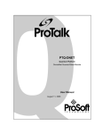
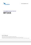
The ADRC Shield can be configured via a set of eight switches to use different pairs of pins for UART
communications. By default it is configured to use ‘Serial’ which appears on UNO digital pins 0 (RX)
and 1 (TX).
To change which pins the shield’s UART is connected to, you change the switches in pairs. So for
example if you want the UART to use pins 2 (RX) and 3 (TX) you simply switch pin 6 to the RX position
and pin 5 to the TX position making sure that all the others are in their centre OFF position.
In the photograph above, the UART is set to use pins 0 and 1.
Now that the hardware configuration is done, we can move on to the fun part; developing the
software and the user interface.
Describing your Project to the ADRC Shield
In order to control your project you need to describe the commands, events and data that your
project uses to the ADRC Shield. The easiest way to do this is to write down a table with each
command, event and any data associated with these and whether the data is read only, write only or
can be both read and written.
To put this in to perspective, we will introduce a simple example. In fact this is the example we used
for our Kickstarter video which is for a project showing how a DC motor can be controlled.
Table 1. Motor Demo Project Commands
Function
Motor power control
Command code
/p?<enum>
Motor speed control
Examples:
/p?0 = turn off
/p?1 = turn on
/s?<range>
Examples:
/s?55
Data type
Integer enumeration
where:
0 = Off
1 = On
Integer range:
0…255
Where 0 is the
slowest and 255 is
the fastest.
Access mode
#readwrite
The motor power
state can be read and
written.
#readwrite
The motor speed
state can be read and
written.
So the first thing you will probably have noticed is that we kept our commands very simple; in fact
single characters. Why use more radio channel bandwidth than you need to?
ADRC REST API
You are probably wondering about the command code format. This is a central part of the ADRC
system, which uses what is known as a REST API. Essentially a REST API is one that has a few
standard methods like HTTP does: GET, PUT, DELETE, POST etc. In a REST system the method
operates on a path, which is a bit like the operand for the method. The path concept is also used by
HTTP in which a URL is a more complex kind of path.
In the ADRC REST API paths always begin with a slash ‘/’ character. So in Table 1, /p?0, /s?55 are
both paths. Similar to a URL, an ADRC path consists of two parts: a selector and an optional query.
The selector must always be present and it is really the command code. The query part is optional
and represents any data that the command requires or alternatively it is the value of the state being
reported.
It is important to know that the selector can be anything that you want it to be as long as it is
alphanumeric text. Also the query can be anything you want, however ADRC has some formatting
rules for defining common constructs such as: lists, structures, name-value pairs and data types. A
detailed description of the ADRC query syntax is available in a separate document but is not required
that you understand this for the examples in this primer.
Table 2. ADRC Access Modes
Access mode
#readonly
#writeonly
#readwrite
#disabled
Description
A read-only selector means that the value cannot be changed by a
controller, but its value can be read. This is common for a device
like a sensor where for example you can read the temperature it is
measuring but obviously you cannot change it.
A write-only selector means that the value can be changed by a
controller but cannot be read. This is common for a device such as
a television with an infrared remote control. You can command it to
change the channel but you cannot ask it which channel it is
currently set to.
A read-write selector means that a controller can both change and
read the state.
This mode is generally used in RML templates for selectors that
have not been fully defined yet. It will not be used in any examples
in this document.
Writing your first RML
Now that we have written down the commands and events for our project, we can begin to describe
it in a language called RML, which stands for Resource Modelling Language. RML is an XML based
language. You can think of it as being similar to HTML where HTML describes a webpage so that a
Web browser can draw it on screen, whereas RML describes a device so that a Device Browser or
other ADRC client can draw it on screen and also do many other useful things as well.
An RML document begins with the device root tag as follows:
<device xmlns=”http://rml.xped.com”>
… RML tags go in here …
</device>
At this point you should know that you don’t ever have to write an RML document from scratch. It is
always a good idea for find an existing RML file that is close to what you want to do. Xped provides a
few standard blank templates that you can copy and then complete for your device. The simplest
one is shown here:
<device xmlns=”http://rml.xped.com”>
<description>
<manufacturer></manufacturer>
<mmodel></mmodel>
<category></category>
<version></version>
<web></web>
</description>
<model>
<-- Your model items go in here -->
</model>
<view>
<screen name=”main”>
<devicebox bind=””>
<!-- Your UI widgets go in here -->
</devicebox>
</screen>
</view>
<menu>
<menuitem>unpair</menuitem>
<!-- menuitem>set-pin</menuitem -->
<!-- menuitem>factory-reset</menuitem -->
</menu>
</device>
Filling in the description section
So let’s start filling out the blank template for our Motor Demo project.
<description>
<manufacturer>Xped</manufacturer>
<mmodel>MotorDemo</mmodel>
<category>8006</category>
<version>1.0</version>
<web>www.xped.com/arduino/motordemo</web>
</description>
The manufacturer tag contains the name of your company or even your own name if you don’t have
a company.
The mmodel tag contains the manufacturer model code for the device. This can be anything you like
as long as the combination of manufacturer and mmodel is unique throughout the world.
The category tag represents the broad class of device that your device belongs to. It is really only
used to determine which default icon is displayed by the Device Browser for your device. Xped
allocates these and here is a partial list of some of the categories available:
0000
8002
8003
8004
8005
8006
8007
8008
8009
Unknown device
Infrared Blaster
Power Outlet
Variable Power Outlet
Sensor
Actuator
Light Switch
Dishwasher
ADRC Shield
In our example since the device is a motor controller it belongs to the Actuator category.
The version tag specifies the version of the RML for your device and NOT the version of the device’s
hardware.
Finally the web tag (which is optional) specifies the URL that you want an NFC enabled phone to
jump to when it is tapped on your project.
Filling in the model section
Now that the description section is done we can use RML to describe the commands we wrote down
in Table 1.
The /p command is an enumeration type so it is specified like this:
<enum id=”power” cmd=”/p” mode=”#readwrite”>
<item name=”Off” value=”0”/>
<item name=”On” value=”1”/>
</enum>
The /s command is a range type so it is specified like this:
<range id=”speed” cmd=”/s” min=”0” max=”255” step=”5”/>
The default value for the mode attribute is #readwrite so we didn’t need to add it in these cases but
we did in one instance so you could see it how it is used.
And this completes the model section, which all put together now looks like this:
<model>
<enum id=”power” cmd=”/p” mode=”#readwrite”>
<item name=”Off” value=”0”/>
<item name=”On” value=”1”/>
</enum>
<range id=”speed” cmd=”/s” min=”0” max=”255” step=”5”/>
</model>
RML provides several other model items which are not used in this example. For further details you
should refer to our book ‘RML in a Nutshell’.
Filling in the view section
The user interface (UI) of your device is what the user sees and interacts with. In terms of user
experience it is the most important thing. So you had better make it a good one. Luckily RML
provides a very rich palette for constructing your UI. At present there are over 25 widgets available
and RML provides style sheeting so there are endless ways to make your UI beautiful and functional.
Before we get into how we implemented the UI for the Motor Demo project we need to cover off
some basic RML and Device Browser concepts.
Firstly, RML and the Device Browser implement the Model View Controller (MVC) design pattern.
MVC is a powerful paradigm for separating data processing logic, display processing logic and control
logic. You can see this in the way RML is partitioned; the data is described in the model section, the
display is described in the view section and although not present in this particular example, any
control logic would be described in a controller section. For many applications, procedural controller
logic is not required as default logic is generated by the Device Browser from RML declarations.
Secondly, view items are bound to model items via the bind attribute present in the view item. Let’s
look at an example. In the model section we just wrote we have this model item:
<enum id=”power” cmd=”/p” mode=”#readwrite”>
<item name=”Off” value=”0”/>
<item name=”On” value=”1”/>
</enum>
We want to represent the power state data visually to the user. RML provides several widgets that
can present enumeration data including radio groups, toggle switches, slide switches and others. The
designer can choose the style that best suits their application. In our example we chose to use a
toggle switch as users are familiar with using this kind of physical switch to turn an appliance on and
off. So here is how you do this in the view section:
<toggleswitch bind=”power”/>
The first thing to notice is that the bind attribute of the toggle switch widget links to the id attribute
of the model item it is bound to; in this case the power model item. This binding creates an implicit
view-controller pair where activating the on-screen widget sends a control signal to the model item
which in turn generates the appropriate commands to send to the actual device. All this is
automatically done for you by the Device Browser so you don’t have to worry about it!
Now for the other model item:
<range id=”speed” cmd=”/s” min=”0” max=”255” step=”5”/>
This is a range model item and RML provides several widgets that can present range data including
sliders, progress bars, scroll dials and others. We chose to use a scroll dial wheel widget:
<scrolldialwheel bind=”speed”/>
Now we are going to look at the entire view section for our example and how it looks on screen.
<view>
<screen name=”main”>
<groupbox title=”$(NICKNAME)” skin=”wood”>
<controlbox bind=”power” stretch=”2”>
<localetitle><en>Power</en></localetitle>
<toggleswitch bind=”power”/>
</controlbox>
<controlbox bind=”speed” stretch=”4”>
<localetitle><en>Speed</en></localetitle>
<scrolldialwheel bind=”speed”/>
</controlbox>
<spacer stretch=”4”/>
</groupbox>
</screen>
</view>
You are probably wondering what all the other stuff in the view section is for. RML provides three
main types of elements for the view: visual containers, controls and layout items. Sizing, spacing and
order are governed by layout managers. Those of you that have built graphical interfaces using Java
will be familiar with this style of development. For those of you that are not, it is very worthwhile
learning how to work with this type of system as it enables sophisticated interfaces to be built that
can automatically rescale for displays with different sizes or resolutions. This primer is not the place
to discuss this topic in full, however we will briefly cover the most important concepts introduced in
the above view section.
A view may consist of one or more screens that the user can navigate between. Each screen must
have one outermost visual container of type devicebox or groupbox. This outermost visual container
may contain any number of child containers, layout items and controls.
Controlbox is a special child container that monitors the communication initiated by the control it
contains and displays a coloured dot to indicate the state: in-progress (yellow), error (red) and
confirmed (invisible).
Localetitle is a textual element that allows the contents to be specified in more than one language.
The text is displayed by the parent item using the language installed on the phone.
Spacer is a layout item that adds fixed or dynamic spacing between other items.
Configuring the menu section
The menu section is the final section of the simple generic template. This section configures which of
the standard device menu functions the Device Browser will be present to the user. The options
available are:
Table 3. Device menu options
Item
unpair
set-pin
factory-reset
Function
The user can unpair the device from the system.
The user can set a security PIN number on the device.
The user can request the device to reset back to factory default
settings.
For the Motor Demo project the only option we want is for the user to be able to unpair the device
from the system. So we leave the menu section the same as it is in the template.
Writing the Arduino Code
Now that the RML for our device is done we can write a little bit of Arduino code to bring everything
to life. In order to make the task of coding easy, a library is supplied for the ADRC Shield. This library
can be downloaded from http://www.xped.com/arduino.
ADRC library
You install the ADRC library in the same way as any other Arduino library. If you are not familiar with
how to do this, please refer to documentation provided at http://www.arduino.cc.
Include the library into your project as follows:
#include <adrc.h>
The library defines two classes that provide the API for working with the ADRC Shield. The main class
is named ADRC. This provides functions for initializing the shield and receiving and responding to
messages from the user interface running on a smartphone. The other class is named RCPMsg and is
provided to make it easy to construct and deconstruct these messages. In case you were wondering,
RCP stands for Resource Control Protocol which is the REST protocol that the ADRC system is built
on.
Declaring global objects
In most cases you will want to declare an instance of the ADRC class that is global in the application.
ADRC Adrc(Serial);
This allows you to reference this object from the loop() function and any other functions you may
want to define.
Writing the setup() function
Setting up the shield couldn’t be easier. The first step is to call the begin() function with the serial
port object you want to use and the baud rate.
If the serial port you are using is a hardware serial port, then you can use the highest baud rate
which is 115,200. On the other hand, if you are using a software serial port on the Uno, then the
fastest baud rate you should use is 38,400. If you use a faster rate, the Uno will spend most of its
CPU cycles just bit bashing the serial communications. There will be very little CPU available to do
any real work.
The final setup step is to register the RML code we wrote with the shield. This only needs to be done
once as the RML is stored in a file in the shield’s file system. The hasRML() function is provided to
test whether the shield already has RML registered.
setup()
{
Adrc.begin(115200);
// Initialize the motor shield pins
}
Writing the loop() function
The loop() function is where you receive requests from the UI and respond to them. If your device
can generate unsolicited events, these can be dispatched from here as well.
loop()
{
if (Adrc.available())
{
RCPMsg msg = Adrc.read();
if (msg.isValid())
{
if (msg.isValid())
{
if (msg.method() == RCP_GET)
Adrc.write(msg.createReply(doGetAllState()));
else if (msg.method() == RCP_PUT)
Adrc.write(msg.createReply(doPutRequest(msg)));
}
}
}
}
The above code snippet is how we suggest you structure the loop code for pretty much any project
that simply receives requests from the UI and responds to them. Let’s go through some of the
concepts introduced in the code.
First of all, the API function available() returns true when there is a message from the UI available to
be read. If there is a message you can read it using the read() function. Notice that read() returns an
object of the class RCPMsg. This is very useful as this class allows you to access the various parts of
an RCP message easily. For example if we want to know which REST method applies to the message,
we can use the method() function. As we explained before, RCP only defines a few REST methods
and the only ones that your application can receive from the UI are RCP_GET and RCP_PUT.
Right about now you are probably wondering what the difference is between the RCP_GET and
RCP_PUT methods. The RCP protocol provides for both synchronous and asynchronous operations. A
synchronous operation means that after the originator sends the message, it waits for the intended
recipient to respond with a reply message. If the recipient does not respond, this is an error,
whereas for an asynchronous operation, the originator does not wait for the intended recipient to
respond. If the recipient does respond, it will be by emitting a signal which will be relayed to all
controllers in the system.
Table 4. RCP Application Methods
Method
GET
PUT
Constant
RCP_GET
RCP_PUT
SIGNAL
RCP_SIG
Usage
A controller wants to retrieve an item of state from a device.
A controller wants to change an item of state on a device. If
the device changes state, it will send a signal to all controllers
in the system.
A device will emit a signal when it changes state, whether this
is triggered by a controller or because the state changes of its
own accord.
Finally you need to respond to the incoming request message. To do this you need to create an
appropriate response message which is an object of the class RCPMsg and then pass this as a
parameter to the write() API function.
Fortunately the library makes this really easy using the createReply() function of the RCPMsg class.
Basically you call this function on the incoming message object and it creates the correct type of
response message and returns you a reference to it. You need to supply a single string parameter to
the createReply() function which contains the state of the requested items.
Remember we previously talked about paths, selectors and queries? Well these are the things that
make up the contents of all requests and responses.
For our Motor Demo project, the only path that the UI will request via the RCP_GET method is the
special wildcard path /*. This means give me ALL your state. In the code snippet, we have the
doGetAllState() function which has to return an Arduino String object whose contents are the motor
state variables formatted as paths. Here is how we implemented this function:
String doGetAllState()
{
String powerState = String(“/p?”) + String(digitalRead(POWER_PIN));
String speedState = String(“/s?”) + String(analogRead(SPEED_PIN));
return powerState + String(“\n”) + speedState;
}
Where for example, m?1 means that he motor is on and s?100 means that the speed is set to 100.
The ‘\n’ is the newline character which is the path delimiter.
The RCP_PUT method can request any item of state to be changed so consequently we need to see
which item the UI is requesting. In a similar way to doGetAllState() we will return the state of the
changed item as a String object from the doPutRequest() function. Here is how we implemented this
function:
String doPutRequest(const RCPMsg& msg)
{
if (msg.selector() == “/p”)
digitalWrite(POWER_PIN, msg.query().toInt());
else if (msg.selector() == “/s”)
analogWrite(SPEED_PIN, msg.query().toInt());
return String(msg.selector()) + String(“?”) + String(msg.query());
}
So there it is, this is how you create a simple project with a slick smartphone interface! We have
included three example applications with the ADRC Shield library. These include the RML files and
the Arduino sketches that go with them. For historical reasons, RML file have the ‘.prf’ extension.
In the next section we explain the most important part of all; how you have fun with your new
device
Using your device
Setting up the system
In the introduction section of this primer, we discussed how the Home Hub and the ADRC Shield
hardware are set up. Now is a good time to double check that both of these things are set up
correctly and that the Home Hub is powered on and connected to your Wi-Fi router.
If you have a smartphone that is equipped with NFC you need to turn that function on. Most if not
all smartphones have NFC turned off by default. How you turn NFC on depends on which phone you
have; so you had best refer to the user manual for your particular phone. However having said that,
most phones that have NFC are either Android or Windows based.
For Android based smartphones:
Go to Settings > Wireless & Networks > More
Turn the NFC switch to on
For Windows Mobile 8 based smartphones:
Go to Settings > tap + send
Turn the slide switch to on
The other thing you need to understand about NFC on smartphones is that the manufacturers of
these devices generally DO NOT indicate where the NFC antenna is. That is a problem because NFC is
only sensitive over a range of approximately 2 cm and so if you tap with the wrong part of the phone
nothing will happen. You will have to experiment with your phone to find out where the NFC
sensitive point is. The sensitive point on the ADRC Shield is clearly marked with our touch point
symbol
.
Pairing your project
Right about now you are probably itching to tap your phone on the shield. So do it! If our device
browser app is not installed on your phone, one of two things would have happened. If you filled in
the web tag in your RML then the web browser on your phone will have opened and gone to the URL
you entered. If you did not complete the web tag then the web browser will have gone to
www.xped.com/store/adrc-shield.html which is the default URL for the ADRC Shield.
In order to pair your project with the system you need to install the device browser app on your
smartphone. At this time it is available for Android only so you can go to the Play Store and search
for Xped Device Browser.
After the device browser is installed, start it running and then tap your project again. Remember
make sure you tap the sensitive part of the phone directly on the touch point symbol on the ADRC
Shield. This time you will see the pairing dialog appear.
Enter a nickname for your project and then select the pair button. A progress page will appear and
indicate when pairing is complete.
Use the back button at the top right of the status bar to get back to the device browser main screen
where you will see a new icon for the Motor Demo project.
Understanding the UI
Tap the icon for the project and then click the power button. If all is well you will see the motor turn
on and begin operating. Move the scroller to change the motor speed.
You may have noticed that when the controls are operated, a yellow dot appears briefly in the top
right corner of the control’s box. This dot indicates the state of the operation.
Yellow means that the command has been sent to the device and it is waiting for a response. When
a response arrives, the dot disappears. If a response is expected but no response arrives, the dot
turns red.
A red dot means that the state of the device could not be confirmed. This can happen when the
radio reception is poor; for instance if you get too far away from the device. The controller will keep
trying to ascertain the state of the device for a period of time. So if you move back in to range, the
dot will disappear. If you do not see any yellow or red dots, this means that the state on the control
screen matches the true state of the actual device.
HAVE FUN