1
PTQ-DNET
Quantum Platform
DeviceNet Scanner/Slave Module
User Manual
August 11, 2008
Please Read This Notice
Successful application of this module requires a reasonable working knowledge of the Schneider Electric
Quantum hardware, the PTQ-DNET Module and the application in which the combination is to be used. For
this reason, it is important that those responsible for implementation satisfy themselves that the combination
will meet the needs of the application without exposing personnel or equipment to unsafe or inappropriate
working conditions.
This manual is provided to assist the user. Every attempt has been made to ensure that the information
provided is accurate and a true reflection of the product's installation requirements. In order to ensure a
complete understanding of the operation of the product, the user should read all applicable Schneider
Electric documentation on the operation of the Schneider Electric hardware.
Under no conditions will ProSoft Technology be responsible or liable for indirect or consequential damages
resulting from the use or application of the product.
Reproduction of the contents of this manual, in whole or in part, without written permission from ProSoft
Technology is prohibited.
Information in this manual is subject to change without notice and does not represent a commitment on the
part of ProSoft Technology Improvements and/or changes in this manual or the product may be made at any
time. These changes will be made periodically to correct technical inaccuracies or typographical errors.
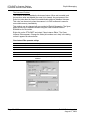
PTQ Installation and Operating Instructions
The statement "power, input and output (I/O) wiring must be in accordance with Class I,
Division 2 wiring methods Article 501-10(b) of the National Electrical Code, NFPA 70 for
installations in the U.S., or as specified in section 18-1J2 of the Canadian Electrical
Code for installations within Canada and in accordance with the authority having
jurisdiction".
The following or equivalent warnings shall be included:
A Warning - Explosion Hazard - Substitution of components may Impair Suitability for
Class I, Division 2;
B Warning - Explosion Hazard - When in Hazardous Locations, Turn off Power before
replacing Wiring Modules, and
C Warning - Explosion Hazard - Do not Disconnect Equipment unless Power has been
switched Off or the Area is known to be Nonhazardous.
D Caution: The Cell used in this Device may Present a Fire or Chemical Burn Hazard if
Mistreated. Do not Disassemble, Heat above 100°C (212°F) or Incinerate.
Important Notice:
CAUTION: THE CELL USED IN THIS DEVICE MAY PRESENT A FIRE
OR CHEMICAL BURN HAZARD IF MISTREATED. DO NOT
DISASSEMBLE, HEAT ABOVE 100°C (212°F) OR INCINERATE.
Maximum battery load = 200 µA.
Maximum battery charge voltage = 3.4 VDC.
Maximum battery charge current = 500 µA.
Maximum battery discharge current = 30 µA.
Your Feedback Please
We always want you to feel that you made the right decision to use our products. If you have suggestions,
comments, compliments or complaints about the product, documentation or support, please write or call us.
ProSoft Technology
1675 Chester Avenue, Fourth Floor
Bakersfield, CA 93301
+1 (661) 716-5100
+1 (661) 716-5101 (Fax)
http://www.prosoft-technology.com
Copyright © ProSoft Technology, Inc. 2000 - 2008. All Rights Reserved.
PTQ-DNET User Manual
August 11, 2008
PSFT.DNET.PTQ.UM.08.08.08
ProSoft Technology ®, ProLinx ®, inRAx ®, ProTalk® and RadioLinx ® are Registered Trademarks of
ProSoft Technology, Inc.
Contents
PTQ-DNET ♦ Quantum Platform
DeviceNet Scanner/Slave Module
Contents
Please Read This Notice
2
PTQ Installation and Operating Instructions ....................................................................................... 2
Important Notice:................................................................................................................................. 2
Your Feedback Please........................................................................................................................ 3
Guide to the PTQ-DNET User Manual
7
1
9
Start Here
1.1
2
ProTalk Module Carton Contents.............................................................................. 9
Configuring the Processor with UnityPro XL
2.1
2.2
2.3
2.4
2.5
2.6
3
Configuring the Module in Scanner Mode
3.1
3.2
3.3
4
Configuring the Module in Slave Mode
5.1
5.2
35
Derived Function Blocks Overview ......................................................................... 35
PTQ-DNET Function Blocks Operation Overview .................................................. 36
Configuring the Processor with Concept
6.1
6.2
6.3
6.4
6.5
6.6
6.7
6.8
6.9
6.10
6.11
7
31
Setup scanner module as a slave device................................................................ 31
PTQ-DNET with Unity Pro XL Function Block
6
21
Software and Hardware Requirements ................................................................... 21
Configure the Module .............................................................................................. 22
Connect to the DeviceNet Network ......................................................................... 28
4.1
5
11
Create a New Project .............................................................................................. 11
Add the PTQ Module to the Project ........................................................................ 13
Set up Data Memory in the Project ......................................................................... 14
Build the Project ...................................................................................................... 15
Connect Your PC to the Processor ......................................................................... 16
Download the Project to the Processor................................................................... 19
Install the 1788-EN2DN DeviceNet Interface
7.1
ProSoft Technology, Inc.
August 11, 2008
45
Overview ................................................................................................................. 45
Before You Begin .................................................................................................... 46
Information for Concept Version 2.6 Users ............................................................. 46
Step 1: Installing MDC Configuration Files ............................................................. 46
Step 2: Convert the Function Blocks....................................................................... 48
Step 3: Setup the Concept Project.......................................................................... 49
Step 4: Create the Function Block Instances .......................................................... 52
Step 5: Download the Concept Project ................................................................... 55
Using the Concept Project....................................................................................... 56
Using Function Blocks............................................................................................. 56
EXPLICIT Message Overview................................................................................. 58
59
Use RSNetWorx for DeviceNet Software to Locate the Module on the Network.... 61
Page 5 of 220
Contents
PTQ-DNET ♦ Quantum Platform
DeviceNet Scanner/Slave Module
Configure the PTQ-DNET Scanner
8
8.1
8.2
8.3
8.4
8.5
9
Register the PTQ-DNET EDS file ........................................................................... 65
Configuring the PTQ-DNET Scanner ..................................................................... 72
Mapping the Scanner's Memory Tables to State RAM........................................... 83
The Scanner's Input Data ....................................................................................... 86
The Scanner's Output Data .................................................................................... 88
Explicit Messaging
9.1
9.2
9.3
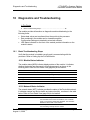
10
Diagnostics and Troubleshooting
13
187
Product Specifications .......................................................................................... 187
Understanding DeviceNet..................................................................................... 191
General PTQ Module Overview............................................................................ 195
How the Processor and Scanner Module Manage Messages ............................. 201
Install the 1784-PCD DeviceNet Interface............................................................ 203
Frequently Asked Questions................................................................................. 208
Support, Service & Warranty
13.1
13.2
13.3
Index
Page 6 of 220
103
Get Started............................................................................................................ 103
Identify Cable System Components ..................................................................... 121
Make Cable Connections...................................................................................... 141
Determine Power Requirements........................................................................... 156
Correct and Prevent Network Problems ............................................................... 178
Understand Select NEC Topics ............................................................................ 184
Power Output Devices .......................................................................................... 185
Reference
12.1
12.2
12.3
12.4
12.5
12.6
99
Basic Troubleshooting Steps .................................................................................. 99
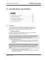
DeviceNet Design and Installation
11.1
11.2
11.3
11.4
11.5
11.6
11.7
12
91
PTQ-DNET Specific Service Codes ....................................................................... 91
Explicit Message Transaction Block ....................................................................... 92
Scan List Auto Configuration .................................................................................. 95
10.1
11
65
209
How to Contact Us: Technical Support................................................................. 209
Return Material Authorization (RMA) Policies and Conditions ............................. 210
LIMITED WARRANTY .......................................................................................... 212
217
ProSoft Technology, Inc.
August 11, 2008
Start Here
PTQ-DNET ♦ Quantum Platform
DeviceNet Scanner/Slave Module
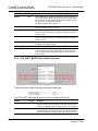
Guide to the PTQ-DNET User Manual
Function
Introduction
Section to Read
Details
→
Start Here (page 9)
This Section introduces the customer to the
module. Included are: package contents,
system requirements, hardware installation, and
basic configuration.
→
Verifying
Communication
(page 183)
This section describes how to verify
communications with the network. Diagnostic
and Troubleshooting procedures.
(Must Do)
Verify Communication,
Diagnostic and
Troubleshooting
Diagnostics and
Troubleshooting
(page 99)
Reference
→
Product Specifications
Functional Overview
Glossary
Support, Service, and
Warranty
Index
ProSoft Technology, Inc.
August 11, 2008
These sections contain general references
associated with this product, Specifications, and
Functional Overview the Functional Overview.
(page 103)
Reference (page
187)
Product
Specifications (page
187)
→
Support, Service
and Warranty (page
209)
This section contains Support, Service and
Warranty information.
Index of chapters.
Page 7 of 220
PTQ-DNET ♦ Quantum Platform
DeviceNet Scanner/Slave Module
Page 8 of 220
Start Here
ProSoft Technology, Inc.
August 11, 2008
Start Here
1
PTQ-DNET ♦ Quantum Platform
DeviceNet Scanner/Slave Module
Start Here
In This Chapter
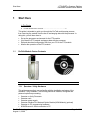
ProTalk Module Carton Contents ............................................................ 9
This guide is intended to guide you through the ProTalk module setup process,
from removing the module from the box to exchanging data with the processor. In
doing this, you will learn how to:
1.1
Set up the processor environment for the PTQ module
View how the PTQ module exchanges data with the processor
Edit and download configuration files from your PC to the PTQ module
Monitor the operation of the PTQ module
ProTalk Module Carton Contents
ProTalk Module
ProSoft Solutions CD
1.1.1 Quantum / Unity Hardware
This guide assumes that you are familiar with the installation and setup of the
Quantum / Unity hardware. The following should be installed, configured and
powered up before proceeding:
Quantum or Unity Processor
Quantum rack
Quantum power supply
Quantum Modbus Plus Network Option Module (NOM Module) (optional)
Quantum to PC programming hardware
NOM Ethernet or Serial connection to PC
ProSoft Technology, Inc.
August 11, 2008
Page 9 of 220
PTQ-DNET ♦ Quantum Platform
DeviceNet Scanner/Slave Module
Start Here
1.1.2 PC and PC Software
Windows-based PC with at least one COM port
Quantum programming software installed on machine
or
Concept™ PLC Programming Software version 2.6
or
ProWORX PLC Programming Software
or
UnityPro XL PLC Programming Software
HyperTerminal (used in this guide) This is a communication program that is
included with Microsoft Windows. You can normally find it in Start /
Programs / accessories / Communications.
Note: ProTalk modules are compatible with common Quantum / Unity programming applications,
including Concept and UnityPro XL. For all other programming applications, please contact
technical support.
Page 10 of 220
ProSoft Technology, Inc.
August 11, 2008
Configuring the Processor with UnityPro XL
2
PTQ-DNET ♦ Quantum Platform
DeviceNet Scanner/Slave Module
Configuring the Processor with UnityPro XL
In This Chapter
Create a New Project ............................................................................ 11
Add the PTQ Module to the Project....................................................... 13
Set up Data Memory in the Project........................................................ 14
Build the Project .................................................................................... 15
Connect Your PC to the Processor ....................................................... 16
Download the Project to the Processor ................................................. 19
The following steps are designed to ensure that the processor (Quantum or
Unity) is able to transfer data successfully with the PTQ module. As part of this
procedure, you will use UnityPro XL to create a project, add the PTQ module to
the project, set up data memory for the project, and then download the project to
the processor.
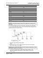
2.1
Create a New Project
The first step is to open UnityPro XL and create a new project.
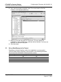
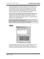
1
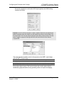
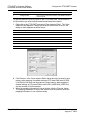
In the New Project dialog box, choose the CPU type. In the following
illustration, the CPU is 140 CPU 651 60. Choose the processor type that
matches your own hardware configuration, if it differs from the example. Click
OK to continue.
ProSoft Technology, Inc.
August 11, 2008
Page 11 of 220
PTQ-DNET ♦ Quantum Platform
DeviceNet Scanner/Slave Module
Configuring the Processor with UnityPro XL
2
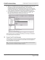
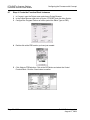
The next step is to add a power supply to the project. In the Project Browser,
expand the Configuration folder, and then double-click the 1:LocalBus icon.
This action opens a graphical window showing the arrangement of devices in
your Quantum rack.
3
Select the rack position for the power supply, and then click the right mouse
button to open a shortcut menu. On the shortcut menu, choose New Device..
Page 12 of 220
ProSoft Technology, Inc.
August 11, 2008
Configuring the Processor with UnityPro XL
2.2
PTQ-DNET ♦ Quantum Platform
DeviceNet Scanner/Slave Module
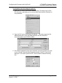
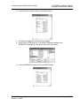
4
Expand the Supply folder, and then select your power supply from the list.
Click OK to continue.
5
Repeat these steps to add any additional devices to your Quantum Rack.
Add the PTQ Module to the Project
The next step is to add the PTQ module.
1
Expand the Communication tree, and select GEN NOM. This module type
provides extended communication capabilities for the Quantum system, and
allows communication between the PLC and the PTQ module without
requiring additional programming.
ProSoft Technology, Inc.
August 11, 2008
Page 13 of 220
PTQ-DNET ♦ Quantum Platform
DeviceNet Scanner/Slave Module
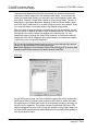
2
Next, enter the module personality value. The correct value for ProTalk
modules is 1060 decimal (0424 hex).
3
Before you can save the project in UnityProXL, you must validate the
modifications. Open the Edit menu, and then choose Validate. If no errors are
reported, you can save the project.
Save the project.
4
2.3
Configuring the Processor with UnityPro XL
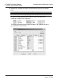
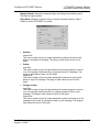
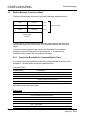
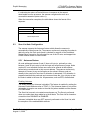
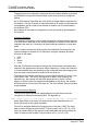
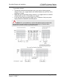
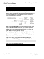
Set up Data Memory in the Project
Depending on the data transfer needs of your application, you may need to
review the data memory allocation in the processor. In the following illustration,
the processor has allocated the following memory values:
Quantum Registers
Unity Registers
0x
%M
256
1x
%I
256
4x
%MW
1024
3x
%IW
1024
Page 14 of 220
Words
ProSoft Technology, Inc.
August 11, 2008
Configuring the Processor with UnityPro XL
PTQ-DNET ♦ Quantum Platform
DeviceNet Scanner/Slave Module
Important: If the module transfers more data to these registers than you have configured in the
processor's memory allocation, the data from the module may overwrite other data in the
processor, and cause the processor to report an error. After you have finished editing the module's
configuration file, review the memory usage, and adjust the processor memory allocation as
needed.
2.4
Build the Project
Whenever you update the configuration of your PTQ module or the processor,
you must import the changed configuration from the module, and then build
(compile) the project before downloading it to the processor.
Note: The following steps show you how to build the project in Unity Pro XL. This is not intended to
provide detailed information on using Unity Pro XL, or debugging your programs. Refer to the
documentation for your processor and for Unity Pro XL for specialized information.
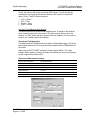
To build (compile) the project:
1
Review the elements of the project in the Project Browser.
ProSoft Technology, Inc.
August 11, 2008
Page 15 of 220
PTQ-DNET ♦ Quantum Platform
DeviceNet Scanner/Slave Module
2
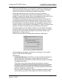
3
Configuring the Processor with UnityPro XL
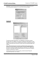
When you are satisfied that you are ready to download the project, open the
Build menu, and then choose Rebuild all Project. This action builds
(compiles) the project into a form that the processor can use to execute the
instructions in the project file. This task may take several minutes, depending
on the complexity of the project and the resources available on your PC.
As the project is built, Unity Pro XL reports its process in a Progress dialog
box, with details appearing in a pane at the bottom of the window. The
following illustration shows the build process under way.
After the build process is completed successfully, the next step is to download
the compiled project to the processor.
2.5
Connect Your PC to the Processor
The next step is to connect to the processor so that you can download the project
file. The processor uses this project file to communicate over the backplane to
modules identified in the project file.
Note: If you have never connected from the PC to your processor before, you must verify that the
necessary port drivers are installed and available to UnityPro XL.
Page 16 of 220
ProSoft Technology, Inc.
August 11, 2008
Configuring the Processor with UnityPro XL
PTQ-DNET ♦ Quantum Platform
DeviceNet Scanner/Slave Module
To verify address and driver settings in UnityPro XL:
1
Open the PLC menu, and choose Standard Mode. This action turns off the
PLC Simulator, and allows you to communicate directly with the Quantum or
Unity hardware.
2
Open the PLC menu, and choose Set address... This action opens the Set
address dialog box. Open the Media dropdown list and choose the
connection type to use (TCPIP or USB).
3
If the Media dropdown list does not contain the connection method you wish
to use, click the Communication Parameters button in the PLC area of the
dialog box. This action opens the PLC Communication Parameters dialog
box.
ProSoft Technology, Inc.
August 11, 2008
Page 17 of 220
PTQ-DNET ♦ Quantum Platform
DeviceNet Scanner/Slave Module
Configuring the Processor with UnityPro XL
4
Click the Driver Settings button to open the SCHNEIDER Drivers
management Properties dialog box.
5
Click the Install/update button to specify the location of the Setup.exe file
containing the drivers to use. You will need your UnityPro XL installation
disks for this step.
6
Click the Browse button to locate the Setup.exe file to execute, and then
execute the setup program. After the installation, restart your PC if you are
prompted to do so. Refer to your Schneider Electric documentation for more
information on installing drivers for UnityPro XL.
2.5.1 Connecting to the Processor with TCPIP
The next step is to download (copy) the project file to the processor. The
following steps demonstrate how to use an Ethernet cable connected from the
Processor to your PC through an Ethernet hub or switch. Other connection
methods may also be available, depending on the hardware configuration of your
processor, and the communication drivers installed in UnityPro XL.
1
2
If you have not already done so, connect your PC and the processor to an
Ethernet hub.
Open the PLC menu, and then choose Set address.
Important: Notice that the Set address dialog box is divided into two areas. Enter the address
and media type in the PLC area of the dialog box, not the Simulator area.
3
Enter the IP address in the address field. In the Media dropdown list, choose
TCPIP.
Page 18 of 220
ProSoft Technology, Inc.
August 11, 2008
Configuring the Processor with UnityPro XL
4
PTQ-DNET ♦ Quantum Platform
DeviceNet Scanner/Slave Module
Click the Test Connection button to verify that your settings are correct.
The next step is to download the Project to the Processor.
2.6
Download the Project to the Processor
1
2
3
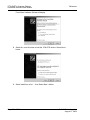
Open the PLC menu and then choose Connect. This action opens a
connection between the Unity Pro XL software and the processor, using the
address and media type settings you configured in the previous step.
On the PLC menu, choose Transfer Project to PLC. This action opens the
Transfer Project to PLC dialog box. If you would like the PLC to go to "Run"
mode immediately after the transfer is complete, select (check) the PLC Run
after Transfer check box.
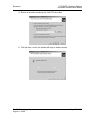
Click the Transfer button to download the project to the processor. As the
project is transferred, Unity Pro XL reports its process in a Progress dialog
box, with details appearing in a pane at the bottom of the window.
When the transfer is complete, place the processor in Run mode.
ProSoft Technology, Inc.
August 11, 2008
Page 19 of 220
PTQ-DNET ♦ Quantum Platform
DeviceNet Scanner/Slave Module
Page 20 of 220
Configuring the Processor with UnityPro XL
ProSoft Technology, Inc.
August 11, 2008
Configuring the Module in Scanner Mode
3
PTQ-DNET ♦ Quantum Platform
DeviceNet Scanner/Slave Module
Configuring the Module in Scanner Mode
In This Chapter
Software and Hardware Requirements ................................................. 21
Configure the Module ............................................................................ 22
Connect to the DeviceNet Network ....................................................... 28
Note: The intent of the sample ladder program is to demonstrate that the module, the DeviceNet
network, and the processor are correctly configured and communicating with each other. Your
actual configuration will most likely be different from this sample ladder program. After you have
completed the steps in this section, you will need to refer to the remainder of this User Manual for
information on how to customize your installation.
3.1
Software and Hardware Requirements
3.1.1 Software Requirements
Before you install the scanner module, make sure you have the following
software:
Personal computer with Microsoft Windows™ XP or later operating system
Rockwell Automation's RSNetWorx for DeviceNet Configuration software or
equivalent (ProSoft Technology part number PSW-DNET).
Rockwell Automation's 1784-PCD PCMCIA DeviceNet (PC to DeviceNet
communication adapter). (Please contact ProSoft Technology for price and
availability)
3.1.2 Electronic Data Sheet Requirement
To use the new features of this release, the scanner module requires the latest
EDS file for the ProSoft Technology DeviceNet Configuration software. The
module includes the EDS file when shipped.
Refer to Register the PTQ-DNET EDS file (page 65) for information on how to
obtain and register the EDS file.
3.1.3 Hardware Requirements
The PTQ-DNET Scanner Module is compatible only with the Quantum processor
line local chassis using Concept or UnityPro software.
ProSoft Technology, Inc.
August 11, 2008
Page 21 of 220
PTQ-DNET ♦ Quantum Platform
DeviceNet Scanner/Slave Module
3.2
Configuring the Module in Scanner Mode
Configure the Module
In this step of the setup process, you will configure the parameters that affect the
interface between the PTQ module and the Quantum processor. These
parameters indicate:
The physical position of the module in the rack.
The starting memory address in the processor's State RAM for the module's
input and output data images. For the purpose of this example, we
recommend a starting address of 1000 for the input image and 1500 for the
output image.
To begin, verify that the processor is correctly positioned in the rack, and is
powered up. Connect your PC to the DeviceNet, using a communication adapter
Interface (purchased separately, this manual refers to the PSFT-1784-PCD
PCMCIA interface available from ProSoft Technology) and RSNetWorx for
DeviceNet communication software (ProSoft Technology part number PSWDNET). The PTQ-DNET module should also be connected to the DeviceNet
network properly configured with appropriate network power supply. (Please refer
to DeviceNet Design and Installation (page 103))
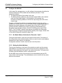
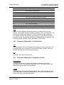
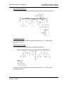
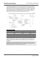
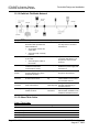
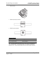
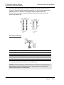
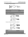
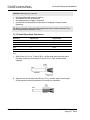
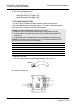
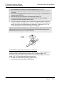
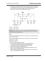
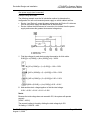
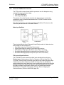
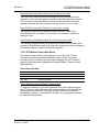
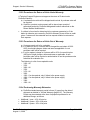
3.2.1 Set Node Address Switches for Channels 1 and 2
The figure below shows a view of the rear panel of the module. The location of
the configuration rotary and bank switch, which are used to set the node address
and data rate of the scanner, are identified.
Configuration switches 3 and 4 should be set to the Off position.
3.2.2 Setting the Node Address
The two rotary switches on the back of the module are used to set the scanner
node address. The module must be removed from the rack to change the node
address. Node Addresses 0 through 63 are valid on DeviceNet. The scanner will
not start if the node address is set to a value above 63.
Set the MSD rotary switch to the tens digit of the node address and the LSD
rotary switch to the ones digit. The node address must not conflict with any other
device on the network.
Page 22 of 220
ProSoft Technology, Inc.
August 11, 2008
Configuring the Module in Scanner Mode
PTQ-DNET ♦ Quantum Platform
DeviceNet Scanner/Slave Module
Before you install your module you must set the following switches:
data rate for the DeviceNet channel
scanner node address for each channel
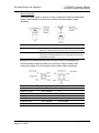
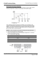
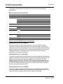
3.2.3 Set the Data Rate Switches
One of the rotary switches on the back of the module is used to set the scanner
data rate (refer to Rear Panel View (page 22)). The module must be removed
from the rack to change the data rate.
Data rate rotary switch determine the data rate, as shown in the table below.
Data Rate
Switch Position
125K baud
0
250K baud
1
500K baud
2
ProSoft Technology, Inc.
August 11, 2008
Page 23 of 220
PTQ-DNET ♦ Quantum Platform
DeviceNet Scanner/Slave Module
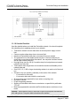
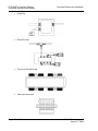
Configuring the Module in Scanner Mode
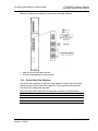
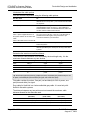
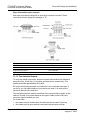
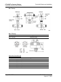
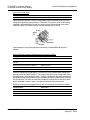
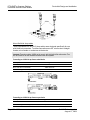
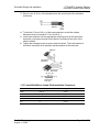
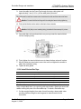
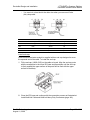
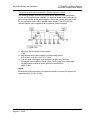
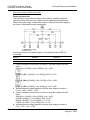
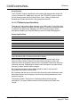
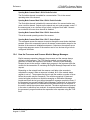
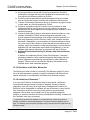
Front Panel View
The figure below shows the indicators and connectors that are visible from the
front of the module.
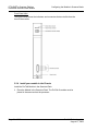
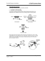
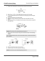
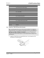
3.2.4 Install your module in the Chassis
Install the ProTalk Module in the Quantum Rack
1
Place the Module in the Quantum Rack. The ProTalk Q module must be
placed in the same rack as the processor.
Page 24 of 220
ProSoft Technology, Inc.
August 11, 2008
Configuring the Module in Scanner Mode
PTQ-DNET ♦ Quantum Platform
DeviceNet Scanner/Slave Module
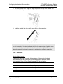
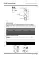
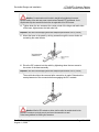
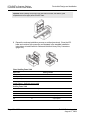
2
Tilt the module at a 45° angle and align the pegs at the top of the module with
slots on the backplane.
3
Push the module into place until it seats firmly in the backplane.
CAUTION: The PTQ module is hot-swappable, meaning that you can install and remove it while
the rack is powered up. You should not assume that this is the case for all types of modules unless
the user manual for the product explicitly states that the module is hot-swappable. Failure to
observe this precaution could result in damage to the module and any equipment connected to it.
3.2.5 Indicators
Module Status Indicator
The module status (MS) indicator displays status of the module. It indicates
whether the device has power and is functioning properly as shown in the
following table. Refer to Front Panel View (page 24) for its location.
Module Status indicator
Module Status:
Off
There is no power applied to the module.
Green
The module is operating normally.
Flashing Green
The module is not configured.
Flashing Red
There is an invalid configuration.
Red
The module has an unrecoverable fault.
ProSoft Technology, Inc.
August 11, 2008
Page 25 of 220
PTQ-DNET ♦ Quantum Platform
DeviceNet Scanner/Slave Module
Configuring the Module in Scanner Mode
Network Status Indicator
The network status (NS) indicator provides the status of the DeviceNet network.
It indicates scanner and device health and network activity, as shown in the table
below. Refer to Front Panel View (page 24) for its location.
Network Status Indicator
Network Status:
Off
The device has no power or the channel is disabled for
communication due to a bus off condition, loss of network power, or
it has been intentionally disabled. The channel is disabled for
DeviceNet communication.
Green
Normal operation. All slave devices in the scan list are
communicating normally with the module.
Flashing Green
The two-digit numeric display for the channel indicates an error code
that provides more information about the condition of the channel.
The channel is enabled but no communication is occurring.
Flashing Red
The two-digit numeric display for the channel displays an error code
that provides more information about the condition of the channel. At
least one of the slave devices in the module's scan list table has
failed to communicate with the module. The network has faulted.
Red
The communications channel has failed. The two digit numeric
display for the channel displays an error code that provides more
information about the condition of the channel. The module may be
defective.
3.2.6 Node Address/Status Display
The module has two-digit numeric display for node address/status indication of
diagnostic information about the scanner and devices in its scan list. The display
alternates at approximately 1 second intervals between node status and node
address.
For slave devices in the scanner's scan list, if the device is functioning normally
its node address and status will not be shown. If there is a communication
problem, the device's status followed by its node address will be shown.
For the scanner, the scanner's status followed by its node address will always be
shown. Once the scanner is in Run mode and functioning normally, the scanner's
node address is shown and the scanner's status is no longer shown.
The display cycles through devices' status/node address in a round-robin
fashion.
The status codes are defined in the table below.
Status Code
Description
0 to 63
Normal operation. These codes indicate node addresses.
65
Module is Autoscan Enabled. This value is displayed in Idle Mode only and is
normal if the module is set to enable Autoscan Fixed addressing.
70
Module failed Duplicate Node Address check. Another device on the network
exists at the scanner's node address.
71
Illegal data in scan list (node address alternately flashes). Reconfigure the scan
list.
72
Slave device stopped communicating (node address alternately flashes).
Page 26 of 220
ProSoft Technology, Inc.
August 11, 2008
Configuring the Module in Scanner Mode
PTQ-DNET ♦ Quantum Platform
DeviceNet Scanner/Slave Module
Status Code
Description
73
Slave device's identity information does not match the electronic key in the
scanner's scan list for the node address. Verify that the correct device is at the
node address.
74
A message was received that had more data than the scanner can accept.
75
No traffic detected on the network. Usually this occurs when the scan list is
empty and there are no other scanners on the network.
76
No traffic intended for the scanner detected on the network. Other devices are
talking, but not to the scanner.
77
Slave device's data size does not match the scanner's scan list. The slave
device's configuration may have changed.
78
Slave device at the node address in the scanner's scan list does not exist or fails
to communicate with the scanner. The slave device may be already
communicating with another scanner.
79
Scanner failed to transmit a message. The network may be invalid, there are no
other devices on the network, or the scanner's data rate may not match the
devices on the network.
80
Scanner is in IDLE mode and output data is not being sent to slave devices. Put
controller in RUN mode and enable RUN bit in Module Command Word.
81
Scanner is in FAULT mode. The fault bit is set in the Module Command Word.
82
Error detected in sequence of fragmented I/O messages from slave device. The
slave device's configuration may have changed and may no longer match the
scanner's scan list.
83
Slave device is returning error responses when the scanner attempts to
communicate with it. The slave device's configuration may have changed or it
may be already communicating with another scanner.
84
Scanner is initializing the devices in its scan list. The scanner will clear this
status code once all of its slave devices have been contacted.
85
Slave device is transmitting incorrect length data. Slave device may be defective
or is dynamically changing its data size.
86
Slave device is producing zero length data (idle state) while scanner is in Run
Mode. Slave device may need to be reconfigured.
87
A slave device whose inputs are being shared is not communicating with its
primary scanner. The slave device's primary scanner must be scanning the slave
device for the scanner to receive the device's shared inputs.
88
The I/O connection types (polled, strobed, etc.) between a slave device whose
inputs are being shared and its primary scanner does not match the shared input
connection of the scanner. The scanner's shared input connection's type(s) must
be the same as, or a subset of, the primary connection's type(s).
89
Scanner's initialization of a slave device using Auto Device Replacement
parameters has failed. Either the scanner's Configuration Recovery data for the
slave device is invalid or the slave device is not compatible with the scanner's
scan list for that node address.
90
The scanner is disabled because the DISABLE bit in the Module Command
Word is set.
91
Scanner has detected communication errors on the network and is now in the
Bus-Off condition. The scanner may be set to the wrong data rate. The sources
of network interference must be removed. The scanner must be restarted.
92
Scanner detects no network power. Once network power is applied, the scanner
will restart.
ProSoft Technology, Inc.
August 11, 2008
Page 27 of 220
PTQ-DNET ♦ Quantum Platform
DeviceNet Scanner/Slave Module
3.3
Configuring the Module in Scanner Mode
Status Code
Description
95
Module firmware update is in progress. Do not remove power from the module or
reset the module while the firmware update is in progress.
97
Not used.
98
Unrecoverable firmware failure. Service or replace the module.
99
Unrecoverable hardware failure. Service or replace the module.
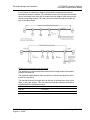
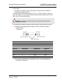
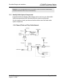
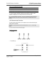
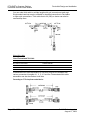
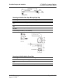
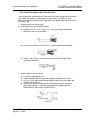
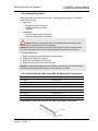
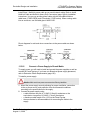
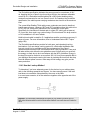
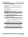
Connect to the DeviceNet Network
The module includes a dual row 5-pin plug for attaching to the DeviceNet
network, as shown in Front Panel View. Wire the plug according to DeviceNet
specifications, matching insulation colors to the color code on the plug and
secure the wires with the screw terminals. The plug must be removed from the
module to attach the wires.
Install the plug into the 5 pin socket on the module and secure by tightening the
screw locks.
The module's DeviceNet circuitry is isolated from the rest of the module circuitry,
and DeviceNet power may be applied before the module is powered in the rack.
Wire Color
Wire Identity
Usage Round
Usage Flat
white
CAN_H
signal
signal
blue
CAN_L
signal
signal
bare
drain
shield
n/a
black
V-
power
power
red
V+
power
power
Open Connector Type Pin Outs
Note: Please refer to DeviceNet Design and Installation (page 103).
3.3.1 Terminate the network
The terminating resistor reduces reflections of the communication signals on the
network. Choose your resistor based on the type of cable (round or flat) and
connector (open or sealed) you use.
For round cable:
the resistor may be sealed when the end node uses a sealed T-port tap
the resistor may be open when the end node uses an open-style tap
For flat cable:
Page 28 of 220
ProSoft Technology, Inc.
August 11, 2008
Configuring the Module in Scanner Mode
PTQ-DNET ♦ Quantum Platform
DeviceNet Scanner/Slave Module
the resistor is a snap-on cap for the KwikLink connector base, available in
sealed and unsealed versions
You must attach a terminating resistor equal to 120 ohms, 5% or greater or 121
ohms, 1%, 1/4W, to each end of the trunk cable. You must connect these
resistors directly across the blue and white wires of the DeviceNet cable.
ATTENTION: If you do not use terminating resistors as described, the DeviceNet
cable system will not operate properly.
Open-Style Terminating Resistors
121 ohms, 1%, 1/4W resistors connecting the white and blue conductors in
micro- or mini-style attach to:
open-style T-Port taps
trunk lines using terminator blocks
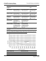
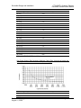
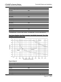
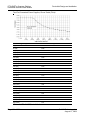
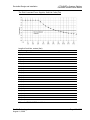
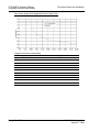
Supply power
The cable system requires the power supply to have a rise time of less than 250
milliseconds to within 5% of its rated output voltage. You should verify the
following:
the power supply has its own current limit protection
fuse protection is provided for each segment of the cable system
o any section leading away from a power supply must have protection
the power supply is sized correctly to provide each device with its required
power
derate the supply for temperature using the manufacturer's guidelines
Use the power supply to power the DeviceNet cable system only. If a device
requires a separate 24V power source other than the DeviceNet power
source, you should use an additional 24V power source.
ProSoft Technology, Inc.
August 11, 2008
Page 29 of 220
PTQ-DNET ♦ Quantum Platform
DeviceNet Scanner/Slave Module
Page 30 of 220
Configuring the Module in Scanner Mode
ProSoft Technology, Inc.
August 11, 2008
Configuring the Module in Slave Mode
4
PTQ-DNET ♦ Quantum Platform
DeviceNet Scanner/Slave Module
Configuring the Module in Slave Mode
In This Chapter
4.1
Setup scanner module as a slave device .............................................. 31
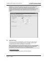
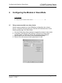
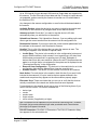
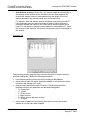
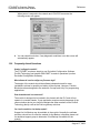
Setup scanner module as a slave device
Select a scanner module icon in the RSNetWorx configuration view, choose
Device > Properties from the main menu, and then click the Module tab. On the
Module property page, click Slave Mode.
1
2
3
4
Click the Enable Slave Mode checkbox to operate the scanner in slave mode.
If necessary, edit the Input sizes (polled or COS/cyclic) or Output sizes
(strobed, polled, or COS/cyclic) for the I/O messaging type(s) desired.
When finished, click OK to return to the Module property page.
Edit all of the other scanner module parameters as usual.
ProSoft Technology, Inc.
August 11, 2008
Page 31 of 220
PTQ-DNET ♦ Quantum Platform
DeviceNet Scanner/Slave Module
Configuring the Module in Slave Mode
4.1.1 Slave mode
Slave mode enables one scanner on a DeviceNet network to provide I/O data to
any other scanner on that same DeviceNet network. When you elect to make a
scanner a slave (on the Module property page, click Slave Mode), you specify
the sizes of the input and output data, as well as expose the input or output data
associated with that scanner to every other scanner on the network. Further, on
the Input and Output tabs, you then determine what addresses will be used in the
memory map.
For more information on where I/O data is mapped when you select a scanner for
slave mode, consider the following table:
I/O data from the:
Is sent to the:
And is mapped to the following locations in the
Slave mode scanner:
Master scanner:
Slave mode scanner
Master scanner
output data table
(Output tab)
input data table (Input tab)
Master scanner
Slave mode scanner
input data table (Input
tab)
output data table (Output
tab)
Strobed:
Output Size
This is the number of bytes of output data that the scanner will send to this
device in a strobed I/O message. The range of valid values is from 0 to 8
bytes.
Polled
Input Size
This is the number of bytes of input data that the scanner expects to receive
in an I/O message from this device in response to a poll I/O message. The
range of valid values is from 0 to 255 bytes.
Output Size
This is the number of bytes of output data that the scanner will send to this
device in a poll I/O message. The range of valid values is from 0 to 255
bytes.
Page 32 of 220
ProSoft Technology, Inc.
August 11, 2008
Configuring the Module in Slave Mode
PTQ-DNET ♦ Quantum Platform
DeviceNet Scanner/Slave Module
Change of State / Cyclic
Input Size
This is the number of bytes of input data that the scanner expects to receive
in an I/O message from this device for a change-of-state (COS) or cyclic
message. The range of valid values is from 0 to 255 bytes
Output Size
This is the number of bytes of output data that the scanner will send in an I/O
message to this device in a change-of-state or cyclic message. The range of
valid values is from 0 to 255 bytes.
ProSoft Technology, Inc.
August 11, 2008
Page 33 of 220
PTQ-DNET ♦ Quantum Platform
DeviceNet Scanner/Slave Module
Page 34 of 220
Configuring the Module in Slave Mode
ProSoft Technology, Inc.
August 11, 2008
PTQ-DNET with Unity Pro XL Function Block
5
PTQ-DNET ♦ Quantum Platform
DeviceNet Scanner/Slave Module
PTQ-DNET with Unity Pro XL Function Block
In This Chapter
5.1
Derived Function Blocks Overview........................................................ 35
PTQ-DNET Function Blocks Operation Overview ................................. 36
Derived Function Blocks Overview
The Unity Pro XL programming language for Schneider Electric Automation
Quantum processors support user defined function blocks (DFB). The user
function block types (Derived Function Blocks) are developed by the user using
one or more languages (according to the number of sections). These languages
are:
Ladder language
Structured Text language
Instruction List language
Functional block language FBD
A DFB type can have one or more instances where each instance is referenced
by a name (symbol), and possesses DFB data types.
Derived Function blocks defined by Unity Pro XL software are entities containing:
Input and output variables acting as an interface with the application
A processing algorithm that operates input variables and completes the
output variables
Private and public internal variables operated by the processing algorithm.
Using the Derived Function Blocks
To simplify programming procedures, ProSoft Technology has included a Unity
Pro XL XFM Functional Module and sample XEF used for communication with
the PTQ-DNET module. The Functional Module provides easy access to the
scanner's supported function blocks. Specific commands are also provided to
perform explicit messaging functions as with Set and Get commands such as,
"Get Auto Scan State" and "Set Auto Scanner Fixed Address Size".
Note: It is not intended within this reference manual to include in depth programming information.
You should, therefore, be familiar with IEC Function Block programming and Unity Pro XL
programming language.
ProSoft Technology, Inc.
August 11, 2008
Page 35 of 220
PTQ-DNET ♦ Quantum Platform
DeviceNet Scanner/Slave Module
PTQ-DNET with Unity Pro XL Function Block
The PTQ-DNET sample functional Module supports inputs and output variables
used for the PTQ module status, explicit messaging and node cyclic I/O data. All
input information is located in the <Inputs> - InputImage area (data delivered to
the Unity processor) and all output information is located in the <input/output> OutputImage area (data sent to the PTQ module).
5.2
PTQ-DNET Function Blocks Operation Overview
Function block define software components or modules that perform a specific
function. Each function block has its own, pre-defined, set of inputs and outputs.
The function block provided with the PTQ-DNET module contains the logic to
handle DeviceNet cyclic data, status, explicit messages and alarms. It transfers
data between the output/input data type arrays and the corresponding slave
devices.
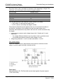
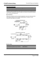
There are two supported Function Blocks for the PTQ-DNET module:
1
2
PTQ_DNET_CTRL: This function block supports the control and status data
of the module.
PTQ_DNET_MSG: This function block supports the processor explicit CIP
messaging associated with the module.
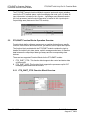
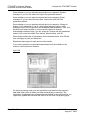
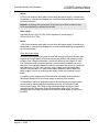
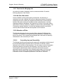
5.2.1 PTQ_DNET_CTRL Function Block Overview
Page 36 of 220
ProSoft Technology, Inc.
August 11, 2008
PTQ-DNET with Unity Pro XL Function Block
PTQ-DNET ♦ Quantum Platform
DeviceNet Scanner/Slave Module
The function block creates and uses the following data types.
The PTQ_DNET_CTRL function block input pins are defined as follows:
Pin Name
Pin Type
Description
InputImage
Input
This input is a comprised of DNET_InputImage structure. The input block consists
of a total of 1024 words. Part of the 1024 words consist of 50 words of Status and
Explicit Messaging area leaving 974 words of input cyclic data.
Run
Input
It is the responsibility of the user to create an instance of this object. The scanner
module maps output data from its scanner output table and discrete outputs to
each device on the network. Inputs are received and mapped into the scanner
input table and discrete inputs. Outputs on the network are under program
control. Placing the CPU into STOP mode places the scanner into idle mode
regardless of the state of the bits in the module command word. Placing the CPU
into RUN mode causes the state of the bits in the module command word to
determine the scanner state.
SetFaultMode
Input
It is the responsibility of the user to create an instance of this object. Setting this
bit to a value of '1' will cause the scanner to stop communicating with devices on
the network. No outputs or inputs are mapped. Outputs on the network are not
under program control. If the scanner was in run, devices will go to their
configured 'fault state.'
Disable
Input
It is the responsibility of the user to create an instance of this object. Setting this
bit to a value of '1' will cause the DeviceNet channel to be become disabled for
communication. No communication may occur over this channel. Outputs on the
network are not under program control. If the scanner was in run, devices will go
to their configured 'fault state.' Numeric error code 90 will occur when channel is
disabled.
Reboot
Input Output It is the responsibility of the user to create an instance of this object. Setting this
bit to value of '1' will cause the scanner to reset as though the reset button had
been pressed. When this command is issued, all scanner communication stops
for the duration of the scanner's initialization sequence. Outputs on the network
are no longer under program control. If the scanner was in run, devices will go to
their configured 'fault state.
IdleMode
Output
If a bit is set, the scanner received a valid DeviceNet idle indication from the
device at the node address. A device in idle mode does not return updated I/O
data to the scanner because the device is not in its run mode.
Error Code 80 will be displayed and is defined as, Scanner is in IDLE mode and
output data is not being sent to slave devices. Put controller in RUN mode and
enable RUN bit in Module Command Word. Check the
RunMode
Output
Device is in Run Mode. The scanner module maps output data from its scanner
output table and discrete outputs to each device on the network. Inputs are
received and mapped into the scanner input table and discrete inputs. Outputs on
the network are under program control. Placing the CPU into STOP mode places
the scanner into idle mode regardless of the state of the bits in the module
command word. Placing the CPU into RUN mode causes the state of the bits in
the module command word to determine the scanner state.
FaultMode
Output
Device is in Fault Mode. The scanner stops communicating with devices on the
network. No outputs or inputs are mapped. Outputs on the network are not under
program control. If the scanner was in run, devices will go to their configured 'fault
state.' Error 81 on the front panel will be displayed.
ProSoft Technology, Inc.
August 11, 2008
Page 37 of 220
PTQ-DNET ♦ Quantum Platform
DeviceNet Scanner/Slave Module
PTQ-DNET with Unity Pro XL Function Block
Pin Name
Pin Type
Description
Disabled
Output
The DeviceNet channel is disabled for communication. No communication may
occur over this channel. Outputs on the network are not under program control. If
the scanner was in run, devices will go to their configured 'fault state.' Numeric
error code 90 will occur when channel is disabled.
Error 90 will be displayed on the front panel.
Failure
Output
DeviceNet device failure detected. Review the device communication failure table
for specific information on each device failed.
AutoVerifyDetected
Output
Indicates that the device autoverify table should be read to determine which
device has incorrect device keying or an incorrectly configured data size in the
scanner's scan list.
ComFail
Output
Indicates that the device communication table should be read to determine which
device has incorrect device keying or an incorrectly configured data size in the
scanner's scan list.
DuplicateNodeFail
Output
Another device on the network exists at the scanner's node address. Error 70 will
be displayed on the module front panel.
ScannerConfigFail
Output
Scanner configuration is missing or corrupted, or module is not in correct slot.
OutputImage
Input Output This input is a comprised of DNET_OutputImage structure. The input block
consists of a total of 1024 words. Part of the 1024 words consist of 33 words
consist of Module Command and Explicit Messaging area leaving 991 words of
output cyclic data.
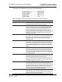
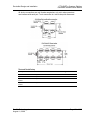
5.2.2 PTQ_DNET_MSG Function Block Overview
The function block creates and uses the following data types.
The PTQ_DNET_MSG function block input pins are defined as follows:
Pin Name
Pin Type
Description
InputImage
Input
This input is a comprised of DNET_InputImage structure. The input block
consists of a total of 1024 words. Part of the 1024 words consist of 50 words
of Status and Explicit Messaging area leaving 974 words of input cyclic data.
ScannerNodeAddress
Input
It is the responsibility of the user to create an instance of this object. Use this
input to address the specific module on the rack. The address is identified on
the unit front display and is set with the rotary switch on the back of the unit.
Page 38 of 220
ProSoft Technology, Inc.
August 11, 2008
PTQ-DNET with Unity Pro XL Function Block
PTQ-DNET ♦ Quantum Platform
DeviceNet Scanner/Slave Module
Pin Name
Pin Type
Description
Autoscansize
Input
It is the responsibility of the user to create an instance of this object. This
integer input in conjunction with the SetAutoscanSize input will determine the
Autoscan Fixed addressing size. Default value is 4. The range is 1 to 32
bytes.
SetAutoScanEnable
Input Output
It is the responsibility of the user to create an instance of this object. Setting
this bit to a value of '1' will cause the DeviceNet channel to be become
disabled for communication. No communication may occur over this channel.
Outputs on the network are not under program control. If the scanner was in
run, devices will go to their configured 'fault state.' Numeric error code 90 will
occur when channel is disabled.
SetAutoScanDisable
Input Output
It is the responsibility of the user to create an instance of this object. Setting
this bit to a value of '1' will cause the scanner operations to stop. No
communications occur over DeviceNet. Outputs on the network are not under
program control. If the scanner was in run, devices will go to their configured
'fault state.' Numeric error code 97 will occur. The scanner must be reset or
power cycled to recover from this state.
SetAutoScanSize
Input Output
It is the responsibility of the user to create an instance of this object. Setting
this bit to value of '1' will cause the scanner to reset as though the reset
button had been pressed. When this command is issued, all scanner
communication stops for the duration of the scanner's initialization sequence.
Outputs on the network are no longer under program control. If the scanner
was in run, devices will go to their configured 'fault state.
GetAutoScanState
Input Output
If a bit is set, the scanner received a valid DeviceNet idle indication from the
device at the node address. A device in idle mode does not return updated
I/O data to the scanner because the device is not in its run mode.
Error Code 80 will be displayed and is defined as, Scanner is in IDLE mode
and output data is not being sent to slave devices. Put controller in RUN
mode and enable RUN bit in Module Command Word. Check the
GetAutoScanSize
Input Output
Device is in Run Mode. The scanner module maps output data from its
scanner output table and discrete outputs to each device on the network.
Inputs are received and mapped into the scanner input table and discrete
inputs. Outputs on the network are under program control. Placing the CPU
into STOP mode places the scanner into idle mode regardless of the state of
the bits in the module command word. Placing the CPU into RUN mode
causes the state of the bits in the module command word to determine the
scanner state.
AutoScanFixedSize
Output
This integer value represents the results from issuing the Get Auto Scan
Fixed Mapping explicit service message triggered by GetAutoScanSize. Valid
display range is 1 to 32 bytes.
AutoScanState
Output
This Boolean value represents the results from issuing the Get Auto Scan
explicit message triggered by the GetAutoScanState. A value of 1 indicates
Autoscan is enabled.
OutputImage
Input Output
This input is a comprised of DNET_OutputImage structure. The input block
consists of a total of 1024 words. Part of the 1024 words consist of 33 words
consist of Module Command and Explicit Messaging area leaving 991 words
of output cyclic data.
ProSoft Technology, Inc.
August 11, 2008
Page 39 of 220
PTQ-DNET ♦ Quantum Platform
DeviceNet Scanner/Slave Module
PTQ-DNET with Unity Pro XL Function Block
5.2.3 PTQ-DNET Input Image
The DNET_InputImage structure consists of the following elements:
Name
Type
Description
StatusWord
Word
Input Status single word of the module. (Refer to Input Block
(page 196))
ExplicitMsgResp
DNET_ExplicitMsg
33 words of Explicit Messaging control response. (Refer to
Explicit Messaging (page 91))
DeviceActiveTable
DNET_Active_Table
4 word table of a bit map representation of Nodes Active on
the network. The scanner assigns one bit to each device on
the network. If the bit is set the device is in the scanners
scan list.
DeviceComFailTable
DNET_Com_Fail_Table
4 word table of a bit map representation of nodes failing on
the network. The scanner assigns one bit to each device on
the network. If a bit is set, the device at the node address is
in the scanner's scan list and is not present, not
communicating, or failed autoverify.
DeviceAutoverifyFailTable
DNET_AutoVerify_Fail
4 word table of a bit map representation of nodes. The
scanner assigns one bit to each device on the network. If a
bit is set, the device at the node address is returning device
keying or a data size that does not match the keying or data
size in the scanner's scan list.
DeviceIdleTable
DNET_Idle_Table
4 word table of a bit map representation of nodes. The
scanner assigns one bit to each device on the network. If a
bit is set, the scanner received a valid DeviceNet idle
indication from the device at the node address. A device in
idle mode does not return updated I/O data to the scanner
because the device is not in its run mode.
ScannerScanCounter
Word
The scanner increments this one-word counter whenever a
scan of the DeviceNet devices is completed. The counter
rolls over when it reaches its maximum value.
RealInputs
Array-of-Words
The device cyclic input area of 974 words. This data is
mapped using RSNetWorx Class Instance Editor setting the
State RAM map offset area. Refer to Setting the Quantum
Input and Output State RAM Starting Address. (page 83)
Page 40 of 220
ProSoft Technology, Inc.
August 11, 2008
PTQ-DNET with Unity Pro XL Function Block
PTQ-DNET ♦ Quantum Platform
DeviceNet Scanner/Slave Module
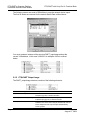
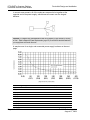
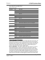
5.2.4 Real Inputs
The below RSNetWorx Class Instance editor example enables the input map and
sets the %IW (3x) starting address to 1000 (03E8)
Further explanation of how the 'Data sent to the device' field is structured is
identified in the below table Value are in hex.
Byte #
Name
Description
1
Input Map Enable
0=Disable Input Table mapping
1=Enable using Input Map Offset
2
Input Map Offset
3
Low byte of starting 3X word
High byte of starting 3X word
4
Output Map Enable
5
Output Map Offset
0=Disable Output table mapping
1=Enable using Output Map Offset
6
7
ProSoft Technology, Inc.
August 11, 2008
Low byte of starting 4X word
high byte of starting 4X word
Configured Slot
Slot in which module must reside to enter
RUN mode and control outputs
Page 41 of 220
PTQ-DNET ♦ Quantum Platform
DeviceNet Scanner/Slave Module
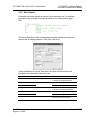
PTQ-DNET with Unity Pro XL Function Block
The following screen was used in RSNetWorx to map the network device inputs.
The first 50 words are reserved for the module Status Data outlined above.
You must create an instance of the structure DNET_InputImage and set the
correct %IW address, in this case %IW1000. An example of this is outlined
below.
5.2.5 PTQ-DNET Output Image
The DNET_outputImage structure consists of the following elements:
Name
Type
Description
Control word
Output
Module Command word. Refer to Module Command Word Bit 00 to 01
Descriptions (page 200) for additional information
ExplicitMsgReq
DNET_ExplicitMsg
33 words dedicated for module explicit message request area. Refer to
Explicit Messaging (page 91) for additional information.
RealOutputs
Array-Of-Word
The device cyclic output area of 991 words. This data is mapped using
RSNetWorx Class Instance Editor setting the State RAM map offset area.
Refer to Setting the Quantum Input and Output State RAM Starting
Address. (page 83)
Page 42 of 220
ProSoft Technology, Inc.
August 11, 2008
PTQ-DNET with Unity Pro XL Function Block
PTQ-DNET ♦ Quantum Platform
DeviceNet Scanner/Slave Module
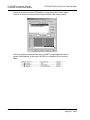
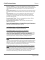
5.2.6 Real Outputs
Command Help below defines the values of the command word. For additional
information refer to Module Command Word Bit 00 to 01 Descriptions (page
200).
The below RSNetWorx Class Instance editor example enables the output map
and sets the 4x starting address to 1500 (5DC) and Slot 3.
Further explanation of how the 'Data sent to the device' field is structured is
identified in the below table Value are in hex.
Byte #
Name
Description
1
Input Map Enable
0=Disable Input Table mapping
1=Enable using Input Map Offset
2
Input Map Offset
3
4
Low byte of starting 3X word
High byte of starting 3X word
Output Map Enable
0=Disable Output table mapping
1=Enable using Output Map Offset
5
Output Map Offset
6
7
ProSoft Technology, Inc.
August 11, 2008
Low byte of starting 4X word
high byte of starting 4X word
Configured Slot
Slot in which module must reside to enter
RUN mode and control outputs
Page 43 of 220
PTQ-DNET ♦ Quantum Platform
DeviceNet Scanner/Slave Module
PTQ-DNET with Unity Pro XL Function Block
The below screen was used in RSNetWorx to map the network device inputs.
The first 50 words are reserved for the module Status Data outlined above.
You must create an instance of the structure DNET_OutputImage and set the
correct %MW address, in this case %IW1500. An example of this is outlined
below.
Page 44 of 220
ProSoft Technology, Inc.
August 11, 2008
Configuring the Processor with Concept
6
PTQ-DNET ♦ Quantum Platform
DeviceNet Scanner/Slave Module
Configuring the Processor with Concept
In This Chapter
6.1
Overview ............................................................................................... 45
Before You Begin .................................................................................. 46
Information for Concept Version 2.6 Users............................................ 46
Step 1: Installing MDC Configuration Files ............................................ 46
Step 2: Convert the Function Blocks ..................................................... 48
Step 3: Setup the Concept Project ........................................................ 49
Step 4: Create the Function Block Instances......................................... 52
Step 5: Download the Concept Project.................................................. 55
Using the Concept Project..................................................................... 56
Using Function Blocks ........................................................................... 56
EXPLICIT Message Overview ............................................................... 58
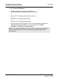
Overview
This section will guide you through the steps required to setup your Concept
Project with the PTQ-DNET module. There are a total of 5 steps required as
follows:
Step 1: Convert the Function Blocks
The .ASC function blocks that are provided for convience, must be converted
before used in the Concept project. This step shows how to convert the
function blocks from .ASC to .DFB format.
Step 2: Setup the Concept Project
This step shows how to setup the Concept Project and configure the required
amount of processor memory for your application.
Step 3: Create the Function Block Instances
This step shows how to create an instance of the function blocks that are
provided and after they were converted. It also shows that some function
block pins must be linked with variables.
Step 4: Download the Project to the Quantum processor
Once you download your project to the Quantum processor the procedure is
completed.
After you followed these steps you can refer to the following topics for more
information on how to perform basic tasks:
ProSoft Technology, Inc.
August 11, 2008
Page 45 of 220
PTQ-DNET ♦ Quantum Platform
DeviceNet Scanner/Slave Module
6.2
Configuring the Processor with Concept
Before You Begin
1
Verify that your PC has the following software tools installed:
o Concept Programming Unit
2
Create a folder C:\project\DFB, where:
C:\project - will store the main Concept project (.PRJ)
C:\project\DFB - will store the data type definition file (.DTY) and the function
blocks that will be used by the Concept project.
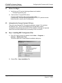
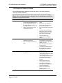
6.3
Information for Concept Version 2.6 Users
This guide uses Concept PLC Programming Software version 2.6 to configure
the Quantum PLC. The ProTalk installation CD includes MDC module
configuration files that help document the PTQ installation. Although not required,
these files should be installed before proceeding to the next section.
6.4
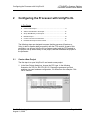
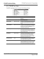
Step 1: Installing MDC Configuration Files
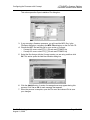
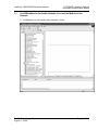
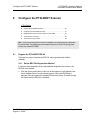
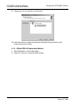
1
From a PC with Concept 2.6 installed, choose Start → Programs →
Concept → ModConnect Tool.
This action opens the Concept Module Installation dialog box.
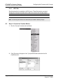
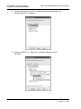
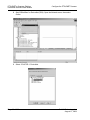
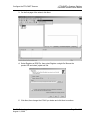
2
Choose File → Open Installation File.
Page 46 of 220
ProSoft Technology, Inc.
August 11, 2008
Configuring the Processor with Concept
PTQ-DNET ♦ Quantum Platform
DeviceNet Scanner/Slave Module
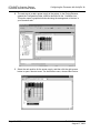
This action opens the Open Installation File dialog box:
If you are using a Quantum processor, you will need the MDC files. In the
File/Open dialog box, navigate to the MDC Files directory on the ProTalk CD.
4 Choose the MDC file and help file for your version of Concept:
o Concept 2.6 users: select PTQ_2_60.mdc and PTQMDC.hlp
o Concept 2.5 users: select PTQ_2_50.mdc and PTQMDC.hlp.
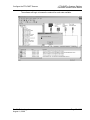
3
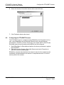
5
Select the files that go with the Concept version you are using, and then click
OK. This action opens the Add New Modules dialog box.
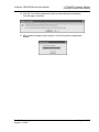
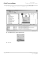
6
Click the Add All button. A series of message boxes may appear during this
process. Click Yes or OK for each message that appears.
When the process is complete, open the File menu and choose Exit to save
your changes.
7
ProSoft Technology, Inc.
August 11, 2008
Page 47 of 220
PTQ-DNET ♦ Quantum Platform
DeviceNet Scanner/Slave Module
Configuring the Processor with Concept
6.4.1 -.ASC files
Each function block is available in ASCII format. These files can be converted
through the Concept Converter tool in order to be used in the Concept project.
File Name
Description
Required
CONTROL.ASC
DNET Control FB
YES
EXPMSG.ASC
EXPLICIT MESSAGES FB
YES
Note: You must copy the files to the DFB section that you created in "Before you begin".
6.5
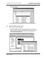
Step 2: Convert the Function Blocks
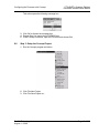
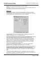
1
Run the Concept Converter tool as follows:
2
Click File-Import. Navigate to the C:\project\DFB folder and select the file
CONTROL.ASC
Page 48 of 220
ProSoft Technology, Inc.
August 11, 2008
Configuring the Processor with Concept
PTQ-DNET ♦ Quantum Platform
DeviceNet Scanner/Slave Module
This action opens the following message box.
3
4
5
6.6
Click OK to dismiss the message box.
Repeat Step 2 to import the file EXPMSG.asc.
In the Concept Converter, open the File menu and choose Exit.
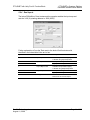
Step 3: Setup the Concept Project
1
Run the Concept program as follows:
2
3
Click File-New Project.
Click File-Save Project as…
ProSoft Technology, Inc.
August 11, 2008
Page 49 of 220
PTQ-DNET ♦ Quantum Platform
DeviceNet Scanner/Slave Module
Configuring the Processor with Concept
4
Navigate to the C:\project folder as the destination folder, and save the
project as PTQDNET. Confirm the save operation.
5
You may be prompted to copy the local DFB Directory as well. Choose the
action that best meets your needs.
6
Configure the general settings for your application. Select the correct
Quantum processor type (PLC Selection) and other modules that will be
located at the Quantum rack.
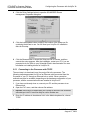
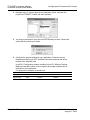
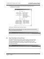
In the PLC Configuration window, double-click on PLC Memory Partition.
Make sure that the number of input registers and output registers will be
sufficient for your application.
For the previous example we would have:
Total Size
Start Address
Last Address
Input image
1024
301000
302023
Output image
1024
401500
402523
Page 50 of 220
ProSoft Technology, Inc.
August 11, 2008
Configuring the Processor with Concept
PTQ-DNET ♦ Quantum Platform
DeviceNet Scanner/Slave Module
So for this example we could select 2000 input registers and 4000 holding
registers as follows:
Important: Failure to correctly configure the number of registers required for your application will
cause the backplane driver not to transfer any data between the processor and the module. Click
File-Close Project. Click File Open-Project and reopen the file that you have just saved. This step
allows Concept to recognize the data type definitions and function blocks that are located in
C:\project\DFB
The most important variables used for this project are the DNET_Input Image
and the DNET_Output Image:
Variable
Transferred From
Transferred To
Description
DNET_In_Image
PTQ-DNET
Quantum
All Input status and data
DNET_Out_Image
PTQ-DNET
Quantum
All Output control and data
Status: the status data can be used to monitor the status of the module and the
Device Net network (input). The function blocks also use the status data for
handshaking purposes when issuing operating mode and explicit messaging.
ProSoft Technology, Inc.
August 11, 2008
Page 51 of 220
PTQ-DNET ♦ Quantum Platform
DeviceNet Scanner/Slave Module
6.7
Configuring the Processor with Concept
Step 4: Create the Function Block Instances
1
2
3
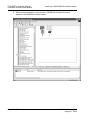
In Concept, open the Project menu and choose Project Browser.
In the Project Browser right-click at Project: PTQDNET and click New Section
Configure the Program Section as follows (select the Editor Type as FBD).
4
Double-click at the FBD section you have just created:
5
Click Objects-FFB Selection. Click at the DFB button and select the Control
Function Block. Click the Close button to confirm.
Page 52 of 220
ProSoft Technology, Inc.
August 11, 2008
Configuring the Processor with Concept
PTQ-DNET ♦ Quantum Platform
DeviceNet Scanner/Slave Module
6
Insert the Control function block at the MAIN section.
7
8
Create new variables to match existing variables.
Select Objects-FFB Selection. Click at the DFB button and select the
EXPMSG Function Block. Click at the Close button to confirm.
9
Insert the EXPMSG function block at the MAIN section.
ProSoft Technology, Inc.
August 11, 2008
Page 53 of 220
PTQ-DNET ♦ Quantum Platform
DeviceNet Scanner/Slave Module
Configuring the Processor with Concept
10 Associate the variables required for the input and output pins for this function
block.
PIN
Type
Default Variable Name1
Data Type
DNETIN
Input
DNET_IN_Image
PTQ_STATUS and Data
DNETOUT
output
DNET_Out_image
PTQ Control and data
You should initially associate these variables to the correct pins before
creating any variables for the other pins:
The following illustration shows example variables. The variables you use for
your application may be different.
Page 54 of 220
ProSoft Technology, Inc.
August 11, 2008
Configuring the Processor with Concept
PTQ-DNET ♦ Quantum Platform
DeviceNet Scanner/Slave Module
11 Repeat the same procedure for all other pins until the function block
configuration is completed:
12 Save the Concept Project (File-Save Project)
Note: While analyzing the project (depending on the number of mailbox function blocks used the
following error message might be generated:
6.8
Step 5: Download the Concept Project
Download the project to the Quantum processor (Online Connect and OnlineDownload...). Once the download operation is concluded there will be a few
warning messages generated in Concept. This is expected since it is just
informing to the user that some input/output variables are being used by more
than one function block.
ProSoft Technology, Inc.
August 11, 2008
Page 55 of 220
PTQ-DNET ♦ Quantum Platform
DeviceNet Scanner/Slave Module
6.9
Configuring the Processor with Concept
Using the Concept Project
6.9.1 Accessing Device Net Data
Input Data is an array of 973 words data type. The following illustration shows an
example where two variables are used to store the PROFIBUS input and output
data.
DNETOUT.outputdata[0] is the first word that is sent from the scanner to the first
slave entered in the scan list.
DNETINPUT.inputdata[0] is the first word of the input data that is related to the
first slave mapped in the scanner list
6.9.2 Accessing Status Data
The module constantly updates the status data to the processor. The status data
provides general information about the module, Device Net active table, auto
verify table fail table and idle table, on the device net network. Refer to input
image data. Table below shows the Device active table and scan counter:
6.10
Using Function Blocks
6.10.1 Overview
The function block sends command messages to the module and also sends and
receives explicit messages over the backplane.
6.10.2 Configuration
The function block contains input, outputs and inputs/outputs pins that must be
associated to specific variables.
The function blocks require the usage of the following pins (common for both
mailbox function blocks):
Page 56 of 220
ProSoft Technology, Inc.
August 11, 2008
Configuring the Processor with Concept
PTQ-DNET ♦ Quantum Platform
DeviceNet Scanner/Slave Module
Pin Name
Pin Type
Description
DNETIN
Input
Input Status and data. It contains the status transferred from the module
function block to receive the acknowledgment that the request was processed
by the module.
DNETOUT
Input/Output
Output Status and data pin. It contains the command word, explicit message
data and the output data to all device slaves.
6.10.3 Trigger inputs
The function block requests are initiated by the "trigger" pins that are defined as
an input/output pin. The mailbox request is initiated after the application moves a
value of 1 to the trigger register.
The current value of all triggers for you application must be equal to 0 in order to
perform a request. If user is using more than one function block, user must add a
program code to guarantee that this condition is satisfied. Therefore, a request is
only allowed when there is no pending request exist, user has to make sure to
get the response before sending another request.
6.10.4 Specific Input Pins
Each function block has input pins specifically for each request. For example, in
order to send a place the scanner in run mode the user needs to toggle Run
scanner bit form 0 to 1 this will place the scanner in run mode.
6.10.5 Specific Output Pins
Each function block contains output pins that are updated after the execution of a
certain request. For example, when user toggle Run scanner bit, output bit in the
function block (run mode) will be set to 1.
Example
If the Run scanner bit is set to 1 the Run mode will turn Green.
You can create a Reference Data Editor table to toggle the value of the Run
scanner bit to ON or OFF.
ProSoft Technology, Inc.
August 11, 2008
Page 57 of 220
PTQ-DNET ♦ Quantum Platform
DeviceNet Scanner/Slave Module
6.11
Configuring the Processor with Concept
EXPLICIT Message Overview
This section provides a brief description on how to use Explicit Message function
block:
6.11.1 Explicit message FB
Function Block: EXPMSG
Description: The MSGEXP function block doesn't cover all messages,
This function block covers only explicit messages that must be issued while the
scanner is in IDLE mode. If your application must issue different explicit
messages (messages with different attributes), you must add your own code.
The following shows a sample instance of the EXPMSG function block:
Before executing any explicit message, you must choose the scanner number
(scanner address)
The auto scan size default is 32 bytes. You can change this value within a range
of 1 to 32 bytes per slave. You can also enable or disable the auto scan feature.
The scanner will add all available slaves on the network to its scan list
automatically within the range of the auto scan size you configured. Refer to
Autoscan Operation for more information on the auto scan feature.
Page 58 of 220
ProSoft Technology, Inc.
August 11, 2008
Install the 1788-EN2DN DeviceNet Interface
7
PTQ-DNET ♦ Quantum Platform
DeviceNet Scanner/Slave Module
Install the 1788-EN2DN DeviceNet Interface
In This Chapter
Use RSNetWorx for DeviceNet Software to Locate the Module on the
Network ................................................................................................. 61
Note: The following steps show you how to build the project in RSNetWorx for DeviceNet from
Rockwell Automation. This is not intended to provide detailed information on using RSNetWorx, or
debugging your programs. Please refer to the documentation for your processor and Rockwell
Automation documentation for RSNetWorx for DeviceNet.
Note: Additional installation information can be obtained directly from the 1788-EN2DN manual
provided with the hardware Ethernet to DeviceNet interface.
Note: This section describes the installation of the 1788-EN2DN interface. Please refer to Install
the 1784-PCD DeviceNet Interface (page 203) if you are using the PCMCIA DeviceNet interface.
1
Connect the Ethernet cable to the RJ-45 port on the end of the linking device.
Do not connect power to the linking device at this time.
2
Start RSNetWorx for DeviceNet, and verify that it is connected to the Ethernet
network.
ProSoft Technology, Inc.
August 11, 2008
Page 59 of 220
PTQ-DNET ♦ Quantum Platform
DeviceNet Scanner/Slave Module
Install the 1788-EN2DN DeviceNet Interface
3
Connect the DeviceNet network cable to the DeviceNet connector on the
linking device.
4
Connect the power cable to the linking device.
5
Configure the IP address for the linking device using one of the following
methods.
o IP address configuration DIP switch
o DHCP protocol
o web page
o RSLogix 5000 software (v.13 or greater) and 1788-EN2DN linking device
(revision 2.x or greater)
Refer to the Installation Instructions booklet provided with the linking device
for help with this procedure.
Page 60 of 220
ProSoft Technology, Inc.
August 11, 2008
Install the 1788-EN2DN DeviceNet Interface
7.1
PTQ-DNET ♦ Quantum Platform
DeviceNet Scanner/Slave Module
Use RSNetWorx for DeviceNet Software to Locate the Module on the
Network
1
In RSNetWorx for DeviceNet, select Network / Online.
ProSoft Technology, Inc.
August 11, 2008
Page 61 of 220
PTQ-DNET ♦ Quantum Platform
DeviceNet Scanner/Slave Module
Install the 1788-EN2DN DeviceNet Interface
2
Expand the list of drivers in the in the Browse for Network dialog box, and
then select AB_ETH-1, Ethernet.
3
Expand the AB_ETH1-1, Ethernet icon, and then select DeviceNet,
DeviceNet.
Page 62 of 220
ProSoft Technology, Inc.
August 11, 2008
Install the 1788-EN2DN DeviceNet Interface
PTQ-DNET ♦ Quantum Platform
DeviceNet Scanner/Slave Module
4
Click OK. You will be prompted to upload or download device information.
Click OK again to continue.
5
When asked to upload from the network, click OK to perform a single pass
browse.
ProSoft Technology, Inc.
August 11, 2008
Page 63 of 220
PTQ-DNET ♦ Quantum Platform
DeviceNet Scanner/Slave Module
6
Install the 1788-EN2DN DeviceNet Interface
When the scan completes, notice that the 1788-EN2DN Linking Device now
appears in the RSNetWorx Graph window.
Page 64 of 220
ProSoft Technology, Inc.
August 11, 2008
Configure the PTQ-DNET Scanner
8
PTQ-DNET ♦ Quantum Platform
DeviceNet Scanner/Slave Module
Configure the PTQ-DNET Scanner
In This Chapter
Register the PTQ-DNET EDS file.......................................................... 65
Configuring the PTQ-DNET Scanner .................................................... 72
Mapping the Scanner's Memory Tables to State RAM .......................... 83
The Scanner's Input Data...................................................................... 86
The Scanner's Output Data ................................................................... 88
Note: This part of the setup reviews the setup of RSNetWorx for DeviceNet and the configuration
the network nodes. This software can be purchased directly from the ProSoft Technology sales
channel, part number PSFT-DNET.
8.1
Register the PTQ-DNET EDS file
There are two ways to register the EDS file: online (preferred) and offline
methods.
8.1.1 Online EDS File Registration Method
If Unknown Device appears at the node address assigned to the scanner, the
EDS file is not loaded.
1
Click the right mouse button on the icon at the scanner's node address, and
select Register Device from the shortcut menu. When the EDS Wizard
appears, click Next and select Upload EDS file from device. Proceed through
the wizard until the EDS file is installed.
ProSoft Technology, Inc.
August 11, 2008
Page 65 of 220
PTQ-DNET ♦ Quantum Platform
DeviceNet Scanner/Slave Module
Configure the PTQ-DNET Scanner
2
Start RSNetWorx for DeviceNet (RSN). Open the Network menu, then select
Online.
3
Select 1784-PCD-1, DeviceNet.
Page 66 of 220
ProSoft Technology, Inc.
August 11, 2008
Configure the PTQ-DNET Scanner
PTQ-DNET ♦ Quantum Platform
DeviceNet Scanner/Slave Module
The software will begin to browse the network for each node available.
ProSoft Technology, Inc.
August 11, 2008
Page 67 of 220
PTQ-DNET ♦ Quantum Platform
DeviceNet Scanner/Slave Module
Configure the PTQ-DNET Scanner
4
After the software completes the network update, select the PTQ-DNET
device identified by the node address and click the right mouse button to
open a shortcut menu.
5
On the shortcut menu, choose Register device …
6
Click Next.
Page 68 of 220
ProSoft Technology, Inc.
August 11, 2008
Configure the PTQ-DNET Scanner
7
Select Upload EDS file...
8
Select the green arrow path and click Next.
ProSoft Technology, Inc.
August 11, 2008
PTQ-DNET ♦ Quantum Platform
DeviceNet Scanner/Slave Module
Page 69 of 220
PTQ-DNET ♦ Quantum Platform
DeviceNet Scanner/Slave Module
9
Configure the PTQ-DNET Scanner
Change the icon if you desire, and click Next
10 Click Next button to register the Quantum DeviceNet Scanner and then click
Finish to dismiss the wizard.
8.1.2 Offline EDS file Registration Method
1
2
Start RSNetWorx for DeviceNet (RSN).
Open the Tools menu, and select EDS Wizard.
Page 70 of 220
ProSoft Technology, Inc.
August 11, 2008
Configure the PTQ-DNET Scanner
PTQ-DNET ♦ Quantum Platform
DeviceNet Scanner/Slave Module
3
On the first page of the wizard, click Next.
4
Select Register an EDS File, then select Register a single file. Browse the
product CD and select 'ptqdnt.eds' file.
5
Click Next, then change the ICON if you desire and click Next to continue.
ProSoft Technology, Inc.
August 11, 2008
Page 71 of 220
PTQ-DNET ♦ Quantum Platform
DeviceNet Scanner/Slave Module
8.2
Configure the PTQ-DNET Scanner
6
Select the Quantum DeviceNet Scanner device and click Next.
7
Click Finished to dismiss the wizard.
Configuring the PTQ-DNET Scanner
The PTQ-DNET scanner is configured using RSNetWorx for DeviceNet V4.01 or
later. Using RSNetWorx and a DeviceNet interface card, such as Rockwell
Automation's 1784-PCD, (ProSoft Technology part number PSFT-1784-PCD) the
DeviceNet network can be examined and devices can be configured.
1
2
Start RSNetWorx for DeviceNet and perform the above procedures to register
the PTQ-DNET.
Right click over the Quantum DeviceNet Scanner and select Properties to
open the scanner's property page.
RSNetWorx contains tools that allow the scanner's scan list to be created, saved,
maintained, and downloaded to the scanner. It maps slave device's I/O into the
memory table of the scanner.
Page 72 of 220
ProSoft Technology, Inc.
August 11, 2008
Configure the PTQ-DNET Scanner
PTQ-DNET ♦ Quantum Platform
DeviceNet Scanner/Slave Module
For RSNetWorx for DeviceNet to recognize the PTQ-DNET, an EDS file for the
PTQ-DNET must be installed.
8.2.1 PTQ-DNET Scanner Property dialog box
General Tab
ProSoft Technology, Inc.
August 11, 2008
Page 73 of 220
PTQ-DNET ♦ Quantum Platform
DeviceNet Scanner/Slave Module
Configure the PTQ-DNET Scanner
Name: Unique network name identifier for the PTQ-DNET
Address: The address of unit is set by the rotary switches on the back of the unit
and cannot be changed with this software parameter.
Module Tab
When this tab is selected, a screen asking permission to upload may appear.
Click Download if this is the first time the PTQ-DNET has been set up. You may
select to upload if the module has been previously configured.
Interscan Delay: This is the time delay between consecutive I/O scans. The
range of valid values is from 2 to 9,000 milliseconds.
The scanner uses this period of time to perform non-time-critical communications
on the DeviceNet network, such as communicating with RSNetWorx for
DeviceNet software. Setting this parameter to a very low value increases the
latency for non-time-critical scanner operations, including the time required to
respond to RSLinx Classic software and configuration functions. Setting this
parameter to a very large value reduces the freshness of the I/O data being
collected by the scanner and is not advisable.
Foreground to Background Poll Ratio: This is the ratio of foreground to
background polls. The range of valid values is from 1 to 32,000.
Devices can be polled on every I/O scan (foreground) or they can be polled less
frequently (background). Whether a particular device will be polled in the
foreground or in the background is determined by its Poll Rate parameter on the
Edit I/O Parameters dialog box, which is accessed from the Scan List property
page.
The poll ratio sets the frequency of poll I/O messages to a device in relation to
the number of I/O scans. For example, if the poll ratio is set to 5, the scanner will
poll the selected devices once every six I/O scans.
Page 74 of 220
ProSoft Technology, Inc.
August 11, 2008
Configure the PTQ-DNET Scanner
PTQ-DNET ♦ Quantum Platform
DeviceNet Scanner/Slave Module
Module Defaults: Resets the Interscan Delay and Foreground to Back ground
Poll Ratio to original values.
Slave Mode: Allows the scanner to act as a slave to another scanner. Select
Enable to set the PTQ-DNET as a Slave,
Strobed:
Output Size
This is the number of bytes of output data that the scanner will send to this
device in a strobed I/O message. The range of valid values is from 0 to 8
bytes
Polled:
Input Size
This is the number of bytes of input data that the scanner expects to receive
in an I/O message from this device in response to a poll I/O message. The
range of valid values is from 0 to 255 bytes.
Output Size
This is the number of bytes of output data that the scanner will send to this
device in a poll I/O message. The range of valid values is from 0 to 255
bytes.
Change of State:
Input Size
This is the number of bytes of input data that the scanner expects to receive
in an I/O message from this device for a change-of-state (COS) or cyclic
message. The range of valid values is from 0 to 255 bytes.
Output Size
This is the number of bytes of output data that the scanner will send in an I/O
message to this device in a change-of-state or cyclic message. The range of
valid values is from 0 to 255 bytes.
ProSoft Technology, Inc.
August 11, 2008
Page 75 of 220
PTQ-DNET ♦ Quantum Platform
DeviceNet Scanner/Slave Module
Configure the PTQ-DNET Scanner
Advanced: You should only open the Advanced Module Settings dialog box if
you are specifically requested to do so by ProSoft technical support.
Scanlist Tab
To edit the scan list of the scanner, use RSNetWorx to browse the network.
Double-click the PTQ-DNET and a scanner configuration dialog appears. Using
this dialog, the scan list can be uploaded from the scanner, slave devices can be
added or removed from the scan list, and the scan list can be downloaded to the
scanner.
When adding slave devices, the scanner configuration dialog maps the slave
devices' I/O into the scanner's memory tables. The memory table mapping can
be tailored to match the mapping expected by the Quantum CPU's ladder logic.
Data from a DeviceNet node can be split and put into as many as four different
locations in the scanner I/O tables.
The dialog also permits the scanner timing, such as Interscan Delay and
Expected Packet Rate to be modified.
Page 76 of 220
ProSoft Technology, Inc.
August 11, 2008
Configure the PTQ-DNET Scanner
PTQ-DNET ♦ Quantum Platform
DeviceNet Scanner/Slave Module
Up to 1024 words of Input data and 1024 words of Output data are supported by
the scanner. The first 50 words of Input data and first 33 words of output data are
not mappable, and are used by the scanner to transfer non-I/O related data to
the Quantum CPU.
Any changes to the scanner configuration or scan list should be downloaded to
the scanner.
Available Devices: select the device(s) you want to include in the scanlist and
move them to the Scanlist list by using the Add, and/or Add All buttons.
Automap on Add: Check this if you want to map the device's I/O data
automatically when you add devices to the scanlist.
Upload from Scanner: Click Upload from Scanner, if you are editing online and
want to get the current scanlist from the scanner into the configuration file
Download to Scanner: If you want to send the current scanlist parameters from
the software to the scanner, click Download to Scanner.
Scanlist: This is a list of the devices that you want the scanner to scan. The
following text appears in the scanlist for special cases.
Invalid Slave - The device in the scanlist is in the configuration but does not
support IDNDeviceSlave, which means it is not reporting any I/O data. Note
that this does not mean that it is reporting zero I/O sizes. Examples of
devices that fit into this case would be a device like a KFD that does have an
applet, or a device that is not registered in the system and is displayed as an
"Unrecognized Device" in the configuration.
Removed from Configuration - The device is in the scanlist but is not in the
configuration. Note that the Master/Slave view also uses this text.
Scanlist Conflict - The device is in the scanlist of more than one scanner.
Node Active: For each device in the scanlist, check this box if you want it to be
included in the scanner's I/O cycle. Inactive devices appear dimmed in the
scanlist and everywhere they appear on the other scanner property pages.
Electronic Keys: These are criteria that you can use to verify that the devices
actually connected to the network are the devices that were expected.
For each device in the scanlist, check one or more of the following boxes if you
want to use the criteria. The choices available are:
device type
vendor
product code
major revision
minor revision (if applicable) or higher
Tips: The selections are not independent; they are hierarchical in descending order. This means,
for example, that you cannot select device type unless you selected vendor. Generic devices
(device type 0) will appear in the scanlist.
Edit I/O Parameters: Click Edit I/O Parameters. The Edit I/O Parameter dialog
box appears for the selected device.
ProSoft Technology, Inc.
August 11, 2008
Page 77 of 220
PTQ-DNET ♦ Quantum Platform
DeviceNet Scanner/Slave Module
Configure the PTQ-DNET Scanner
Select whether or not you want the selected device to respond to Strobed
messages. If you do, also select the Output Size parameter desired.
Select whether or not you want the selected device to respond to Polled
messages. If you do, select the Input Size, Output Size, and Poll Rate
parameters desired.
Select whether or not you want the selected device to respond to Change of
State or Cyclic messages. If you do, select either change of state or cyclic
messages, Input Size, Output Size, and Heartbeat Rate parameters. Then, click
Advanced and select whether or not you want the device to issue an
Acknowledge command; and, if you do, select the Timeout and Ack parameters
desired. Also, select the Inhibit Time desired. When finished, click OK.
When finished editing the I/O parameters for the selected device, click OK and
then click Apply to save your selections.
Repeat the above steps for each device in the scanlist.
If you want to send the current scanlist parameters from the software to the
scanner, click Download to Scanner.
Input Tab
On the Input property page, you can map device input data into the scanner's
data table either online or offline and either automatically or manually. This
information is uploaded to the software and downloaded to the scanner when you
respectively upload and download the scan list on the Scan List property page.
Page 78 of 220
ProSoft Technology, Inc.
August 11, 2008
Configure the PTQ-DNET Scanner
PTQ-DNET ♦ Quantum Platform
DeviceNet Scanner/Slave Module
The input map determines where the input data (the data received from each
device) will be mapped into the scanner's data tables. You can select the name
of the data table memory you want the input data mapped to and a start word
offset, if desired. Input data is read from input image tables. The size of these
tables is processor dependent. Mapping to and from these tables is done as a
word index, offset from zero. No other mapping choices are available. There is
no reserved status or command bytes in the mapped image tables.
When you elect to have the software automatically map the input data, you still
have the option of aligning the data on byte or word boundaries. The devices will
be mapped in the order in which they appear in the message list. You can
change the order by clicking the column titles; however, not all column titles will
change the order. When mapping input data manually, you still have the option of
choosing a user-configurable alignment.
Tip: You can use the automatic mapping feature to rough-in the input data map; then, manually,
fine-tune it by using the features on the Input property page.
Note: Refer to Mapping the Scanner's Memory Tables to State RAM (page 83) for necessary steps
required to map the Scanner memory to the Quantum processor State RAM.
Output Tab
On the Output property page, you can map device output data into the scanner's
data table either online or offline and either automatically or manually. This
information is uploaded to the software and downloaded to the scanner when you
respectively upload and download the scan list on the Scan List property page.
ProSoft Technology, Inc.
August 11, 2008
Page 79 of 220
PTQ-DNET ♦ Quantum Platform
DeviceNet Scanner/Slave Module
Configure the PTQ-DNET Scanner
The output map determines where the output data (the data that will be sent to
each device) will be mapped into the scanner's data tables. You can select the
name of the data table memory you want the output data mapped to and a start
word offset, if desired. Output data is written to output image tables. The size of
these tables is processor dependent. Mapping to and from these tables is done
as a word index, offset from zero. No other mapping choices are available. There
is no reserved status or command bytes in the mapped image tables.
When you elect to have the software automatically map the output data, you still
have the option of aligning the data on byte or word boundaries. The devices will
be mapped in the order in which they appear in the message list. You can
change the order by clicking the column titles; however, not all column titles will
change the order. When mapping output data manually, you still have the option
of choosing a user-configurable alignment.
Tip: You can use the automatic mapping feature to rough-in the output data map; then, manually,
fine-tune it by using the features on the Output property page.
Note: Refer to Mapping the Scanner's Memory Tables to State RAM (page 83) for necessary steps
required to map the Scanner memory to the Quantum processor State RAM.
ADR Tab
On the ADR property page, you can configure the automatic device replacement
(ADR) parameters for scanner's that support the ADR feature, which automates
the replacement of a failed slave device on a DeviceNet network by returning it to
the prior level of operation. This feature includes Configuration Recovery (CR)
and Auto-Address Recovery (AAR). Using the controls on this property page, you
can select ADR parameters and enable/disable this functionality either globally or
on a device-specific basis.
Page 80 of 220
ProSoft Technology, Inc.
August 11, 2008
Configure the PTQ-DNET Scanner
PTQ-DNET ♦ Quantum Platform
DeviceNet Scanner/Slave Module
Before using the ADR feature, you may want to consider any restrictions, known
anomalies, and answers to frequently asked questions. (Refer to RSNetWorx
Scanner Online Help for FAQ and known anomalies information)
Enable Auto-Address Recovery: Check this if you want to enable this
functionality in the scanner for the specific device selected in the list. When
enabled, the scanner will change a device's node address from the default (63) to
the address desired by the scanner based upon its Electronic Key.
For example, when the scanner loses a connection to the device at node 37, it
will continually query the device's identity at node 63. When a device is found
that matches the electronic key of the device that the scanner lost at node 37 (if
the Slave address is controlled by software and not hardware switches), it will
attempt to change its node address to node address 37. Upon the success of this
operation, the device's configuration will be downloaded to the network.
If the Slave address is set by hardware switches, you must match the switches
with the lost Slave. The scanner will check for its electronic keying. If it matches
the lost slave (37) the Scanner will establish communication with the newly
added slave as if it was never lost.
Please observe the Warning message when enabling the ADR feature.
Select each device and then the 'Load Device Config' button. Then set each
device fro ADR with the ADR Settings.
ADR Settings:
Configuration Recovery: Check this if you want to enable the storage of a
device configuration in the scanner. When enabled, the scanner will
download the stored configuration to the device before it begins to exchange
I/O data with that device.
This Feature is most useful when used for slaves that have extensive
configuration. If the device fails and Configuration Recovery is not selected,
you must re-enter all of the configuration data to the newly added slave. If
Configuration Recover is selected, you can set the scanner to download the
previous configuration to the new slave.
This control will be enabled only if a device's configuration has been loaded
into the scanner tool (refer to online help for the Load from Project button).
ProSoft Technology, Inc.
August 11, 2008
Page 81 of 220
PTQ-DNET ♦ Quantum Platform
DeviceNet Scanner/Slave Module
Configure the PTQ-DNET Scanner
Auto-Address recovery: Check this if you want to enable this functionality in
the scanner for the specific device selected in the list. When enabled, the
scanner will change a device's node address from the default (63) to the
address desired by the scanner based upon its Electronic Key.
For example, when the scanner loses a connection to the device at node 37,
it will continually query the device's identity at node 63. When a device is
found that matches the electronic key of the device that the scanner lost at
node 37, it will attempt to change its node address to node address 37. Upon
the success of this operation, the device's configuration will be downloaded to
the network.
Summary Tab
The Summary property page provides a concise summary of how the scanner
has been configured. It shows the following information:
node address and the name of the device residing at that address
active status of each I/O device (specifying whether or not the device will be
included in the scanner's I/O cycle)
electronic keys specified for each I/O device. The following shows the
specified electronic key parameter and associated designator:
o D - Device type
o V - Vendor
o P - Product code
o J - Major revision
o R - Major revision and minor revision
o + - or higher
total number of data bytes received by the scanner from the device and
whether or not they have been mapped
Page 82 of 220
ProSoft Technology, Inc.
August 11, 2008
Configure the PTQ-DNET Scanner
PTQ-DNET ♦ Quantum Platform
DeviceNet Scanner/Slave Module
total number of data bytes transmitted from the scanner to the device and
whether or not they have been mapped
Note: All of the information that appears on this property page is read only. If you want to change
any of the parameters, you have to edit them on the appropriate property pages.
8.2.2 Clearing the Scan List
In some situations it is desirable to empty the scan list before configuring the
scan list for the network. To clear the scanner module's scan list, follow these
procedures:
1
2
3
4
5
6
7
8.3
Remove the scanner module from the rack.
Set configuration switch 3 to the On or "1" position. (refer to Rear Panel View
(page 22)).
Reinstall the scanner module and apply power to the rack.
Wait for the Module Status indicator to flash red.
Remove the scanner module from the rack.
Set configuration switch 3 to the Off or "0" position.
Insert scanner module into the rack and apply power.
Mapping the Scanner's Memory Tables to State RAM
The PTQ-DNET cannot transfer data to the Quantum CPU until its I/O memory
table is mapped to the CPU's state RAM. Once mapped, the scanner can
transfer data between the CPU's state RAM and the scanner's slave devices.
The scanner reads data from slave devices (inputs) and maps the data into its
input memory table. The input memory table is then written to the CPU's 3X state
RAM.
The scanner reads data from the CPU's 4X state RAM into its output memory
table. The scanner then sends the data to slave devices according to the scan
list memory map.
8.3.1 Setting the Quantum Input and Output State RAM Starting
Address
The mapping information is contained in the field labeled 'Data sent to the
device'. This field requires 7 bytes (in hex), whose format is defined below.
Byte #
Name
Description
1
Input Map Enable
0=Disable Input Table mapping
1=Enable using Input Map Offset
2
Input Map Offset
Low byte of starting 3X word
Output Map Enable
0=Disable Output table mapping
3
4
High byte of starting 3X word
1=Enable using Output Map Offset
5
Output Map Offset
6
ProSoft Technology, Inc.
August 11, 2008
Low byte of starting 4X word
high byte of starting 4X word
Page 83 of 220
PTQ-DNET ♦ Quantum Platform
DeviceNet Scanner/Slave Module
Configure the PTQ-DNET Scanner
Byte #
Name
Description
7
Configured Slot
Slot in which module must reside to enter RUN mode and
control outputs
To map the scanner's memory tables to the CPU's state RAM, use RSNetWorx
for DeviceNet to go online with the network and browse the network.
1
Right-click on the PTQ-DNET and select 'Class Instance Editor'. The Class
Instance Editor appears. Change the fields (all numbers are in hex) in the
dialog so that it appears as shown below.
Service Code Description:
Other
Service Code Value:
4C
Object Address Class:
90 (hex)
Object Address Instance:
1
Send the attribute ID box:
Unchecked
Object Address Class:
1
Transmit byte size:
Byte
Data Sent to the device:
01 E8 03 01 DC 05 03 (include spaces)
2
3
Click Execute. In the Class Instance Editor dialog above the scanner's input
memory table mapping is enabled starting at CPU state RAM word 301000
(%IW1000) (03e8 hex) and the scanner's output memory table mapping is
enabled starting at CPU state RAM word 401500 (%MW1500) (05DC hex)
and slot number 03 for this sample.
When the mapping information is set as desired, click the 'Execute' button.
The mapping information is sent to the scanner, and the scanner saves the
mapping information in non-volatile memory.
Page 84 of 220
ProSoft Technology, Inc.
August 11, 2008
Configure the PTQ-DNET Scanner
PTQ-DNET ♦ Quantum Platform
DeviceNet Scanner/Slave Module
8.3.2 Reading the Scanner's Memory Table Map
To read the mapping information from the scanner module use the Class
Instance Editor to send the explicit message shown in the dialog below and click
'Execute'.
1
Right-click on the PTQ-DNET and select 'Class Instance Editor'. The Class
Instance Editor appears. Change the fields (all numbers are in hex) in the
dialog so that it appears as shown below.
2
Click Execute. In the Class Instance Editor Dialog above input mapping is
enabled starting at word 301000 (%IW1000) (3e8 hex = 1000) and output
mapping is enabled starting at word 401000 (%MW1500) (5dc hex = 1500).
The CPU's 3X table size is 1024 (400 hex) words and its 4X table size is
1024 words. Slot number is 3 for this example.
Class Instance Editor parameter settings
Service Code Description:
Other
Service Code Value:
4B
Object Address Class:
90 (hex)
Object Address Instance:
1
Send the attribute ID box:
Unchecked
Object Address Class:
1
The text box labeled 'Data received from the device:' contains the mapping
information returned from the module. The mapping information returned from
the module contains 10 bytes (in hex), whose format is shown in the table below.
Byte #
Name
Description
1
Input Map Enable
0=Disable Input Table mapping
1=Enable using Input Map Offset
2
Input Map Offset
3
ProSoft Technology, Inc.
August 11, 2008
Low byte of starting 3X word
High byte of starting 3X word
Page 85 of 220
PTQ-DNET ♦ Quantum Platform
DeviceNet Scanner/Slave Module
Configure the PTQ-DNET Scanner
Byte #
Name
Description
4
Output Map Enable
0=Disable Output table mapping
5
Output Map Offset
1=Enable using Output Map Offset
6
High byte of starting 4X word
7
Configured Slot
Slot in which module must reside to control outputs
8
Number of Words in 3X
table of CPU
Low byte of size of 3X Table
9
10
11
12
8.4
Low byte of starting 4X word
Number of Words in 4X
Table of CPU
High byte of size of 3X Table
Low byte of size of 4X Table
High byte of size of 4X Table
Slot in which module resides This value will contain
0xFF if CPU not installed
Installed Slot
The Scanner's Input Data
The scanner's input memory table supports up to 1024 words. The first 50 words
are reserved for status information from the module. This status information block
is defined in the table below.
Word Offset
Description
0
Module Status Word
1 to 32
Explicit Messaging Response
33 to 36
Device Active Table
37 to 40
Device Communications Failure Table
41 to 44
Device Autoverify Failure Table
45 to 48
Device Idle Table
49
Scanner Scan Counter
50 to 1023
Device Input Data
8.4.1 Module Status Word Offset 0
Bits 0 through 4 of the Module Status Word indicate the current state of the
scanner module. When a Module Command Word command is sent to the
scanner module, the respective bits are set in the Module Status Word when the
command executes. Depending on network load, the scanner may take several
moments to detect network status changes.
Bit 6 indicates that device status tables should be read for more specific
information about which devices failed.
Bit 8 indicates that the device autoverify table should be read to determine which
device has incorrect device keying or an incorrectly configured data size in the
scanner's scan list.
Page 86 of 220
ProSoft Technology, Inc.
August 11, 2008
Configure the PTQ-DNET Scanner
PTQ-DNET ♦ Quantum Platform
DeviceNet Scanner/Slave Module
The following table lists the bits of the Module Status Word and their
descriptions.
Bit Number
Bits
00 to 01
0
0
DeviceNet in Idle mode
Module Status Word
0
1
DeviceNet in run mode
1
0
DeviceNet in fault mode
1
1
Reserved
02 to 03
04
Reserved
0
1
05
Enable DeviceNet
Disable DeviceNet
Reserved
06
0
1
DeviceNet device failure detected
07
0
Scanner Normal
1
Rebooted due to MCW from processor over backplane
0
No failures detected
08
1
09
10
0
1
15
No failures detected
DeviceNet communications failure detected
Reserved
0
No failures detected
1
DeviceNet duplicate node address failure
13
14
DeviceNet autoverify failure detected
Reserved
11
12
No failures detected
Reserved
0
Scanner installed in configured slot
1
Scanner not installed in configured slot
0
Reserved
1
Reserved
Refer to Module Command Word (page 88) for mode descriptions.
8.4.2 Device Active Table
The Device Active Table is a bitmap that assigns one bit to each device on the
network. The scanner assigns one bit to consecutive node addresses.
If a bit is set, the device at the node address is in the scanner's scan list and has
successfully communicated with the scanner. These bits are not cleared if the
slave node goes off-line. The bits are cleared by resetting the scanner.
8.4.3 Device Communications Failure Table
The Device Communications Failure table is a bitmap that that assigns one bit to
each device on the network. The scanner assigns one bit to consecutive node
addresses.
ProSoft Technology, Inc.
August 11, 2008
Page 87 of 220
PTQ-DNET ♦ Quantum Platform
DeviceNet Scanner/Slave Module
Configure the PTQ-DNET Scanner
If a bit is set, the device at the node address is in the scanner's scan list and is
either not present, not communicating, or failed autoverify.
8.4.4 Device Autoverify Failure Table
The Autoverify Failure Table is a bitmap that assigns one bit to each device on
the network. The scanner assigns one bit to consecutive node addresses.
If a bit is set, the device at the node address is returning device keying or a data
size that does not match the keying or data size in the scanner's scan list.
8.4.5 Device Idle Table
The Device Idle Table is a bitmap that assigns one bit to consecutive node
addresses.
If a bit is set, the scanner received a valid DeviceNet idle indication from the
device at the node address. A device in idle mode does not return updated I/O
data to the scanner because the device is not in its run mode.
8.4.6 Scanner Scan Counter
The scanner increments this one-word counter whenever a scan of the
DeviceNet devices is completed. The counter rolls over when it reaches its
maximum value.
8.5
The Scanner's Output Data
The scanner's output memory table supports up to 1024 words. The first
33 words are reserved for control information to the module. This control
information block is defined in the table below.
Word Offset
Description
0
Module Command Word
1 to 32
Explicit Messaging Request
33 to 1023
Device Output Data
8.5.1 Module Command Word offset 0
The following table outlines the module command word's bit numbers and
descriptions.
Bits
Operating Mode
Bit Number
X1
X0
00 to 01
0
0
DeviceNet in idle mode
0
1
DeviceNet in run mode
02 to 03
Page 88 of 220
1
0
DeviceNet in fault mode
1
1
Reserved
1
1
Reserved
ProSoft Technology, Inc.
August 11, 2008
Configure the PTQ-DNET Scanner
04
PTQ-DNET ♦ Quantum Platform
DeviceNet Scanner/Slave Module
0
Enable DeviceNet
1
Disable DeviceNet
05
Reserved
06
Reserved
07
08 to 15
0
Scanner Active
1
Scanner reboot
0
Reserved for future use
8.5.2 Idle
The scanner does not map output data to the devices, but keeps network
connections to devices open so device failures can be detected. Input data is
returned from devices, and mapped into the scanner input table and the discrete
inputs. Outputs on the network are not under program control and will be in their
configured 'idle state.' The scanner must be put into this mode to perform
configuration of the scanner scan list.
8.5.3 Run
The scanner module maps output data from its scanner output table and discrete
outputs to each device on the network. Inputs are received and mapped into the
scanner input table and discrete inputs. Outputs on the network are under
program control. Placing the CPU into STOP mode places the scanner into idle
mode regardless of the state of the bits in the module command word. Placing
the CPU into RUN mode causes the state of the bits in the module command
word to determine the scanner state.
8.5.4 Fault Network
The scanner stops communicating with devices on the network. No outputs or
inputs are mapped. Outputs on the network are not under program control. If the
scanner was in run, devices will go to their configured 'fault state.'
8.5.5 Enable DeviceNet
The DeviceNet channel is enabled for communication. This is the normal
operating state of the channel.
8.5.6 Disable DeviceNet
The DeviceNet channel is disabled for communication. No communication may
occur over this channel. Outputs on the network are not under program control. If
the scanner was in run, devices will go to their configured 'fault state.' Numeric
error code 90 will occur when channel is disabled.
ProSoft Technology, Inc.
August 11, 2008
Page 89 of 220
PTQ-DNET ♦ Quantum Platform
DeviceNet Scanner/Slave Module
Configure the PTQ-DNET Scanner
8.5.7 Scanner Active
This is the normal operating mode of the scanner.
8.5.8 Scanner Reboot
This command causes the scanner to reset as though the reset button had been
pressed. When this command is issued, all scanner communication stops for the
duration of the scanner's initialization sequence. Outputs on the network are no
longer under program control. If the scanner was in run, devices will go to their
configured ‘fault state.
Page 90 of 220
ProSoft Technology, Inc.
August 11, 2008
Explicit Messaging
9
PTQ-DNET ♦ Quantum Platform
DeviceNet Scanner/Slave Module
Explicit Messaging
In This Chapter
PTQ-DNET Specific Service Codes ...................................................... 91
Explicit Message Transaction Block ...................................................... 92
Scan List Auto Configuration ................................................................. 95
Use the Explicit Messaging feature to send asynchronous messages to devices
on the DeviceNet network from the program in the Quantum CPU controller.
The CPU program in Run mode builds a message in the Explicit Message
Request transaction block of the module's output data. The PTQ-DNET module
receives the request and forwards it to the appropriate device. The device
generates a response and the response is forwarded to the CPU in the Explicit
Message Response transaction block of the module's input data.
An Explicit Message can target any device on the DeviceNet network, including
the scanner.
9.1
PTQ-DNET Specific Service Codes
The modules available DeviceNet service codes are listed below.
Note: The Module Memory Map service codes are not available when using the codes from the
processor to the module over the backplane.
Description
Service Code
Type
Class
Instance
Attribute
Data
Auto Scan Fixed
Mapping
10 hex
SET
90
1
11
1 to 32
(bytes)
Auto Scan Enable
10 hex
SET
90
1
10
0 or 1
Module Memory Map
4C hex
Other
(SET)
90
1
1
Refer to
table
Auto Scan Fixed
Mapping
E hex
GET
90
1
11
Auto Scan Enable
E hex
GET
90
1
10
Module Memory Map
4B hex
Other
(GET)
90
1
1
Get Version Info
E hex
GET
90
1
4
ProSoft Technology, Inc.
August 11, 2008
Refer to
DeviceNet
Specifications
Page 91 of 220
PTQ-DNET ♦ Quantum Platform
DeviceNet Scanner/Slave Module
9.2
Explicit Messaging
Explicit Message Transaction Block
The figure below shows the format of an Explicit Message transaction block.
TXID
cmd/status
word 0
port
size
word 1
service
node address
word 2
Transaction Header
Transaction Body
(29 words)
The transaction header identifies the transaction and contains information that
identifies the target. Each of the fields of the transaction header are one byte in
length.
In a request, the transaction body contains the DeviceNet Class, Instance,
Attribute and Service Data portion of the transaction. In a response, the
transaction body contains only the response message.
9.2.1 Transaction Block Word 0: Command/Status Field
In a request, the Command/Status field should contain the desired action for the
transaction. The table below shows the available actions.
Command Code
Command Code
Description
0
Ignore transaction block (block empty)
1
Execute this transaction block
2
Get status of transaction TXID
3
Reset all client/server transactions
4 to 255
Reserved
In a response, this field contains the result of the requested transaction. The
table below shows the status codes.
Status Code
Status Code
Description
0
Ignore transaction block (block empty)
1
Transaction completed successfully
2
Transaction in progress (not ready)
3
Error - slave not in scan list
4
Error - slave offline
5
Error - DeviceNet port disabled/offline
Page 92 of 220
ProSoft Technology, Inc.
August 11, 2008
Explicit Messaging
PTQ-DNET ♦ Quantum Platform
DeviceNet Scanner/Slave Module
Status Code
Description
6
Error - transaction TXID unknown
7
Error - slave not responding to request
8
Error - Invalid command code
9
Error - Scanner out of buffers
10
Error - Other Client/server transaction in progress
11
Error - could not connect to slave device
12
Error - response data too large for block
13
Error - invalid port
14
Error - invalid size specified
15
Error - connection busy
16 to 255
Reserved
TXID
When an Explicit Message Request transaction is created and sent to the
scanner, the controller's program assigns a transaction ID to the transaction. This
is a one-byte integer in the range of 1 to 255 (0 indicates an idle transaction).
The scanner uses this value to track the transaction to completion, and returns
the value with the response that matches the request sent by the processor. The
controller program monitors rollover and usage of TXID values.
9.2.2 Transaction Block Word 1: Port/Size Field
Size
This field contains the size of the data in the transaction body field in bytes. The
transaction body can be as many as 29 words (58 bytes) in length. If the size
exceeds 29 words, an error code will be returned.
Port
This field is not used and should be 0.
9.2.3 Transaction Block Word 2: Node/Service Field
Node Address
This field contains the DeviceNet node address of the device where the
transaction is sent. This value can range from 0 to 63. The node address field
identifies the target device of the transaction.
Service
This field contains the Explicit Message service code, which identifies the type of
Explicit Message is contained in the transaction. The service code defines the
format of the data in the transaction body.
ProSoft Technology, Inc.
August 11, 2008
Page 93 of 220
PTQ-DNET ♦ Quantum Platform
DeviceNet Scanner/Slave Module
Explicit Messaging
9.2.4 Explicit Message Transactions
Requests
DeviceNet Explicit Message requests are always generated by the Quantum
controller. Either the scanner or the slave will generate the response.
To issue a request transaction, the Quantum controller program first builds the
transaction by filling the transaction header appropriately, putting data in the
transaction body according to the service code, and setting the size field to
match the number of bytes in the transaction body. To send the request
message, the command/status field is set to 1 (execute) and the TXID is
changed.
The scanner first copies the request transaction's header to the response
transaction's header, with the command/status field set to 2 (in progress). Once
the transaction is complete, the appropriate status code is loaded with the
completion status and the transaction body contains the response.
The following table shows the typical format of an explicit message transaction
body. All DeviceNet Explicit Messages require a Class and Instance to determine
the object in the device to which the explicit message is targeted.
TXID
command
0
size
service
node address
Class
Instance
Attribute (if required)
Service Data
Note that if the service is Get_Attribute_Single or Set_Attribute_Single, an
attribute value is required. Since the attribute value is only a byte, the upper byte
of that word should be set to 0. If the service does not require an attribute, the
first byte of service data is placed in the low byte of the attribute word, the high
byte of the attribute word is 0, and the remaining bytes of the service data are
placed in the service data field. In all cases, the size field should not include the
high byte of the attribute word.
Responses
A failure to respond to the request within the number of retries or timeout period
specified for the Explicit Message Connection is recognized by the scanner
module as an error. The error code is returned in the status attribute of the
transaction header.
Page 94 of 220
ProSoft Technology, Inc.
August 11, 2008
Explicit Messaging
PTQ-DNET ♦ Quantum Platform
DeviceNet Scanner/Slave Module
If a slave device returns a DeviceNet error in response to the request
downloaded from the processor, the scanner recognizes the error as a
successful transaction (status code =1).
When the transaction completes, the table below shows the format of the
response.
TXID
status
0
size
service
node address
Service Response Data
9.3
Scan List Auto Configuration
The scanner supports the Autoscan feature which allows the scanner to
automatically create its scan list. The scanner continuously searches for nodes to
add to the scan list. Each node found is checked for support of the Predefined
Master/Slave Connection Set, allocated for one of the I/O sets, and mapped into
a fixed location based on node number.
9.3.1 Autoscan Feature
All node addresses between 0 and 61 have a 4 byte (or, optionally a value
between 1 and 32 byte) entry in both the input and output memory maps. Node
number 63 is not scanned to allow new nodes to be entered at that address
before being commissioned to their correct address. The scanner continuously
attempts to connect to any and all nodes on the subnet. When a node not
already in the scan list is found an I/O allocation is attempted. If I/O allocation is
supported and both the produced and consumed sizes are 4 (or n) bytes or less
the node is added to the scan list. All parameters, such as EPR, are defaulted.
Enabling Autoscan
The default setting for Autoscan is disabled. The feature is enabled by setting the
Autoscan Enable attribute value to TRUE (1). The Autoscan feature is only active
(attempting to acquire new nodes to the scan list) when enabled and the scanner
is in IDLE mode.
The Scan List is saved, not created on each power up. The Save is performed
when new nodes have been added on a timed basis. The Scan List is cleared on
a transition from DISABLED to ENABLED.
Autoscan is disabled when any SET access is performed on the Scan List, with
the exception of the enable/disable attribute.
ProSoft Technology, Inc.
August 11, 2008
Page 95 of 220
PTQ-DNET ♦ Quantum Platform
DeviceNet Scanner/Slave Module
Explicit Messaging
The global scanner configuration values are set to the same defaults as provided
by RSNetWorx except the Interscan Delay, which is the previously configured
setting.
Up to 1024 words of Input data and 1024 words of Output data are supported by
the scanner. The first 50 words of Input data and first 33 words of output data are
not mappable, and are used by the scanner to transfer non-I/O related data to
the Quantum CPU.
Any changes to the scanner configuration or scan list should be downloaded to
the scanner.
Autoscan Operation
The Autoscan functionality is active when the feature is enabled and the scanner
is in IDLE mode. When active, the scanner attempts to connect to each node not
enabled in the scan list. Connections to these nodes are made on a round robin
basis.
When a node is found which does support the Predefined Connection Set, the
scanner attempts to allocate an I/O connection using the following Allocation
Choices (in this order):
COS
Poll
Strobe
Cyclic
After the I/O allocation the scanner shall get the Produced and Consumed data
sizes from the appropriate Connection Object instance(s). If either the Produced
or Consumed data sizes are greater than the configured fixed data mapping size,
then the node is rejected and not entered into the scan list.
The scanner will load the electronic key next storing the Vendor ID, Device Type,
and Product Code. This level of keying will be in effect. After obtaining the
electronic key, the scanner will check the target device for Quick Connect
support. If Quick Connect is supported and enabled on the device, the scanner
will set the Quick Connect bit in the scan list. The Auto Address Recovery feature
is also enabled.
Autoscan Memory Mapping
The input and output data will be mapped based on node number and the
configured (or default) fixed mapping size. The algorithm is:
Input (Output) offset = ((Node Number) x (Fixed Mapping Size)) + Data Offset
where Data Offset is 50 words (100 bytes) for the input data table and is 33
words (66 bytes) for the output data table
Thus, when using the default fixed mapping size of 4 bytes (1 DINT) the input
data for node 10 maps to word location 70 (byte location 140 = ((10 x 4) + 100
bytes for header offset) of the scanner's input data table and the output data for
node 10 maps to word location 53 (byte location 106 = ((10 x 4) + 66).
Page 96 of 220
ProSoft Technology, Inc.
August 11, 2008
Explicit Messaging
PTQ-DNET ♦ Quantum Platform
DeviceNet Scanner/Slave Module
Finally, the scanner will set the connection EPR values. The Poll and Strobe
connections will use the global scanner default in the Scanner Configuration
object (75ms). The EPR values used are:
COS = 250ms
Poll = 75ms
Strobe = 75ms
Cyclic = 500ms
Autoscan Fixed Mapping Size Attribute
This attribute allows for different fixed mapping sizes. A change in this attribute
value causes the scan list to be cleared. This value can be set only when the
scanner is in IDLE mode and the Autoscan feature is disabled. The new value is
saved to non-volatile memory immediately.
The Autoscan Fixed Mapping Size
This attribute can be changed with any method of Explicit Messaging. The figure
below shows how to set it to 4 using the Class Instance Editor of RSNetWorx for
DeviceNet.
Right-click on the PTQ-DNET and select 'Class Instance Editor'. The Class
Instance Editor appears. Change the fields (all numbers are in hex) in the dialog
so that it appears as shown below.
Class Instance Editor parameter settings
Service Code Description:
Set Single Attribute
Service Code Value:
10
Object Address Class:
90 (hex)
Object Address Instance:
1
Object Attribute:
11 (hex)
Send the attribute ID box:
Grayed out and checked
Data sent to the device:
default 20(hex) bytes (range 1 to 20hex) = 1 to 32 bytes.
ProSoft Technology, Inc.
August 11, 2008
Page 97 of 220
PTQ-DNET ♦ Quantum Platform
DeviceNet Scanner/Slave Module
Explicit Messaging
The Autoscan Enabled
This attribute enables/disables the Autoscan feature. When set to enable (and
the previous value was disable) the scan list is cleared. Any set access to the
Scan List (other than the Scan List enable/disable attribute) disables Autoscan.
This value can be set only when the scanner is in IDLE mode and is saved to
non-volatile memory immediately.
This attribute can be changed with any method of Explicit Messaging. The figure
below shows how to enable Autoscan using the Class Instance Editor of
RSNetWorx for DeviceNet.
Right-click on the PTQ-DNET and select 'Class Instance Editor'. The Class
Instance Editor appears. Change the fields (all numbers are in hex) in the dialog
so that it appears as shown below.
Class Instance Editor parameter settings
Service Code Description:
Set Single Attribute
Service Code Value:
10
Object Address Class:
90 (hex)
Object Address Instance:
1
Object Attribute:
10 (hex)
Send the attribute ID box:
Grayed out and checked
Data sent to the device:
value can be set 0 (disable) or 1 (enable). The default is
disabled.
Page 98 of 220
ProSoft Technology, Inc.
August 11, 2008
Diagnostics and Troubleshooting
PTQ-DNET ♦ Quantum Platform
DeviceNet Scanner/Slave Module
10 Diagnostics and Troubleshooting
In This Chapter
Basic Troubleshooting Steps................................................................. 99
The module provides information on diagnostics and troubleshooting in the
following forms:
10.1
Status data values are transferred from the module to the processor.
Data contained in the module can be viewed through the
Configuration/Debug port attached to a terminal emulator.
LED status indicators on the front of the module provide information on the
module's status.
Basic Troubleshooting Steps
Verify that the module is installed correctly and is communicating with the
processor. Refer to Setting Up the ProTalk Module.
10.1.1 Module Status Indicator
The module status (MOD) indicator displays status of the module. It indicates
whether the device has power and is functioning properly as shown in the
following table. Refer to Front Panel View (page 24) for its location.
Module Status indicator: (MOD)
Module Status:
Off
There is no power applied to the module.
Green
The module is operating normally.
Flashing Green
The module is not configured.
Flashing Red
There is an invalid configuration.
Red
The module has an unrecoverable fault.
10.1.2 Network Status Indicator
The network status (NET) indicator provides the status of the DeviceNet network.
It indicates scanner and device health and network activity, as shown in the table
below. Refer to Front Panel View (page 24) for its location.
Network Status Indicator: NET
Network Status:
Off
The device has no power or the channel is disabled for
communication due to a bus off condition, loss of network
power, or it has been intentionally disabled. The channel is
disabled for DeviceNet communication.
Green
Normal operation. All slave devices in the scan list are
communicating normally with the module.
ProSoft Technology, Inc.
August 11, 2008
Page 99 of 220
PTQ-DNET ♦ Quantum Platform
DeviceNet Scanner/Slave Module
Diagnostics and Troubleshooting
Network Status Indicator: NET
Network Status:
Flashing Green
The two-digit numeric display for the channel indicates an error
code that provides more information about the condition of the
channel. The channel is enabled but no communication is
occurring.
Flashing Red
The two-digit numeric display for the channel displays an error
code that provides more information about the condition of the
channel. At least one of the slave devices in the module's scan
list table has failed to communicate with the module. The
network has faulted.
Red
The communications channel has failed. The two digit numeric
display for the channel displays an error code that provides
more information about the condition of the channel. The
module may be defective.
10.1.3 Node Address/Status Display
The module has two-digit numeric display for node address/status indication of
diagnostic information about the scanner and devices in its scan list. The display
alternates at approximately 1 second intervals between node status and node
address.
For slave devices in the scanner's scan list, if the device is functioning normally
its node address and status will not be shown. If there is a communication
problem, the device's status followed by its node address will be shown.
For the scanner, the scanner's status followed by its node address will always be
shown. Once the scanner is in Run mode and functioning normally, the scanner's
node address is shown and the scanner's status is no longer shown.
The display cycles through devices' status/node address in a round-robin
fashion.
The status codes are defined in the table below.
Status Code
Description
0 to 63
Normal operation. These codes indicate node addresses.
70
Module failed Duplicate Node Address check. Another device on the network
exists at the scanner's node address.
71
Illegal data in scan list (node address alternately flashes). Reconfigure the scan
list.
72
Slave device stopped communicating (node address alternately flashes).
73
Slave device's identity information does not match the electronic key in the
scanner's scan list for the node address. Verify that the correct device is at the
node address.
74
A message was received that had more data than the scanner can accept.
75
No traffic detected on the network. Usually this occurs when the scan list is
empty and there are no other scanners on the network.
76
No traffic intended for the scanner detected on the network. Other devices are
talking, but not to the scanner.
77
Slave device's data size does not match the scanner's scan list. The slave
device's configuration may have changed.
Page 100 of 220
ProSoft Technology, Inc.
August 11, 2008
Diagnostics and Troubleshooting
PTQ-DNET ♦ Quantum Platform
DeviceNet Scanner/Slave Module
Status Code
Description
78
Slave device at the node address in the scanner's scan list does not exist or fails
to communicate with the scanner. The slave device may be already
communicating with another scanner.
79
Scanner failed to transmit a message. The network may be invalid, there are no
other devices on the network, or the scanner's data rate may not match the
devices on the network.
80
Scanner is in IDLE mode and output data is not being sent to slave devices. Put
controller in RUN mode. and enable RUN bit in Module Command Word.
81
Scanner is in FAULT mode. The fault bit is set in the Module Command Word.
82
Error detected in sequence of fragmented I/O messages from slave device. The
slave device's configuration may have changed and may no longer match the
scanner's scan list.
83
Slave device is returning error responses when the scanner attempts to
communicate with it. The slave device's configuration may have changed or it
may be already communicating with another scanner.
84
Scanner is initializing the devices in its scan list. The scanner will clear this
status code once all of its slave devices have been contacted.
85
Slave device is transmitting incorrect length data. Slave device may be defective
or is dynamically changing its data size.
86
Slave device is producing zero length data (idle state) while scanner is in Run
Mode. Slave device may need to be reconfigured.
87
A slave device whose inputs are being shared is not communicating with its
primary scanner. The slave device's primary scanner must be scanning the slave
device for the scanner to receive the device's shared inputs.
88
The I/O connection types (polled, strobed, etc.) between a slave device whose
inputs are being shared and its primary scanner does not match the shared input
connection of the scanner. The scanner's shared input connection's type(s) must
be the same as, or a subset of, the primary connection's type(s).
89
Scanner's initialization of a slave device using Auto Device Replacement
parameters has failed. Either the scanner's Configuration Recovery data for the
slave device is invalid or the slave device is not compatible with the scanner's
scan list for that node address.
90
The scanner is disabled because the DISABLE bit in the Module Command
Word is set.
91
Scanner has detected communication errors on the network and is now in the
Bus-Off condition. The scanner may be set to the wrong data rate. The sources
of network interference must be removed. The scanner must be restarted.
92
Scanner detects no network power. Once network power is applied, the scanner
will restart.
95
Module firmware update is in progress. Do not remove power from the module or
reset the module while the firmware update is in progress.
97
Not Used.
98
Unrecoverable firmware failure. Service or replace the module.
99
Unrecoverable hardware failure. Service or replace the module.
ProSoft Technology, Inc.
August 11, 2008
Page 101 of 220
PTQ-DNET ♦ Quantum Platform
DeviceNet Scanner/Slave Module
Page 102 of 220
Diagnostics and Troubleshooting
ProSoft Technology, Inc.
August 11, 2008
DeviceNet Design and Installation
PTQ-DNET ♦ Quantum Platform
DeviceNet Scanner/Slave Module
11 DeviceNet Design and Installation
In This Chapter
11.1
Get Started .......................................................................................... 103
Identify Cable System Components .................................................... 121
Make Cable Connections .................................................................... 141
Determine Power Requirements ......................................................... 156
Correct and Prevent Network Problems .............................................. 178
Understand Select NEC Topics........................................................... 184
Power Output Devices......................................................................... 185
Get Started
This section introduces the DeviceNet cable system and provides a brief
overview of how to set up a DeviceNet network efficiently. The steps in this
section describe the basic tasks involved in setting up a network.
11.1.1 Before You Begin
Before you begin laying out your DeviceNet network, take a few minutes to
consider the following decisions you must make.
Tip: After you have selected all DeviceNet devices for your network, calculate the total data size
required by the DeviceNet-networked devices. Compare the total data size required against the
total amount available from the DeviceNet scanner module you have selected.
1
What I/O devices will I need?
o If you plan to hard-wire certain devices to I/O modules, calculate the total
number of discrete I/O points, such as sensors, photoeyes, etc., in your
application.
Tip: All DeviceNet-capable devices require a unique network node number, which counts against
the total node count of 63. If the I/O points are standard discrete versions, they will be connected to
t he DeviceNet network via a discrete I/O-to-DeviceNet adapter. In this case, only the I/O adapter
would require a network node number, allowing you to connect multiple I/O points with one
adapter.
o
o
Calculate the total required analog I/O channels.
Calculate the total I/O points being brought into I/O modules versus direct
connections to the network.
ProSoft Technology, Inc.
August 11, 2008
Page 103 of 220
PTQ-DNET ♦ Quantum Platform
DeviceNet Scanner/Slave Module
o
o
DeviceNet Design and Installation
Decide which type of discrete I/O you will use in your application: sealed
(such as FLEXArmor or MaXum), or open-style (typically contained in
enclosures).
Document the data table requirements for each node. This information will
help you develop the control platform user program.
2
What type of network media is best for my application?
o Determine whether you need a Class 1 or Class 2 cabling system.
o Choose sealed or unsealed media for your application's environment.
o Choose the maximum trunk length allowable within specifications for the
cable type and communication baud rate.
o Ensure that your cumulative cable drop length is within specifications for
the network baud rate.
o Ensure that all individual drop line lengths are </= 20 ft. (6m).
o Ensure that you have one 121Ω terminating resistor at each end of the
trunk line.
3
Which power supply will be adequate for my application?
o Refer to Choose a power supply (page 113) for further details on selecting
a power supply.
4
How do I configure my network?
o You will use RSNetWorx for DeviceNet software to generate an offline
configuration file, which contains all the I/O mapping for your system. This
file will help you develop a control platform user program. Refer to the
online help accompanying RSNetWorx for DeviceNet software for
assistance in adding and configuring devices.
o After you have added devices, use RSNetWorx for DeviceNet software to
commission a node for that device.
o Use RSNetWorx for DeviceNet software to create and download a
scanlist to the master scanner.
11.1.2 Set Up a DeviceNet Network
The following diagram illustrates the steps that you should follow to plan and
install a DeviceNet network. The remainder of this section provides an overview
and examples of each step.
Understand the Media (page 105)
Basic DeviceNet network (page 105)
Terminate the Network (page 110)
Supply Power (page 112)
Ground the Network (page 118)
Use the Checklist (page 120)
Page 104 of 220
ProSoft Technology, Inc.
August 11, 2008
DeviceNet Design and Installation
PTQ-DNET ♦ Quantum Platform
DeviceNet Scanner/Slave Module
Basic DeviceNet network
This figure shows a basic DeviceNet network and calls out its basic components.
Understand the Media
You must terminate the trunk line at both ends with 121Ω, 1%, 1/4W or larger
terminating resistors.
Understand the topology
The DeviceNet cable system uses a trunk/drop line topology.
You must terminate the trunk line at both ends with 121Ω, 1%, 1/4W or larger
terminating resistors.
ProSoft Technology, Inc.
August 11, 2008
Page 105 of 220
PTQ-DNET ♦ Quantum Platform
DeviceNet Scanner/Slave Module
DeviceNet Design and Installation
Understand the cable options
You can connect components using the following cable options.
Use this cable
As
Round (thick)
the trunk line on the DeviceNet network with an outside
diameter of 12.2 mm (0.48 in.). You can also use this cable
for drop lines.
Round (thin)
the drop line connecting devices to the main line with an
outside diameter of 6.9 mm (0.27 in.). This cable has a
smaller diameter and is more flexible than thick cable. You
can also use this cable for the trunk line.
Flat
the trunk line on the DeviceNet network, with dimensions of
19.3 mm x 5.3 mm (0.76 in. x 0.21 in.). This cable has no
predetermined cord lengths, and you are free to put
connections wherever you need them.
Class 1 power supplies allow for an
8A system and the use of Class 1 flat
cable.
Class 2 flat cable must not exceed 4A.
KwikLink drop cable
a non-shielded, 4-conductor drop cable for use only in
KwikLink systems.
Unshielded drop cable
a non-shielded, 4-conductor drop cable (with an outside
diameter specified by the vendor) for use only in flat cable
systems
Determine the maximum trunk line distance
The maximum cable distance is not necessarily the trunk length only. It is the
maximum distance between any two devices.
Wire Color
Wire Identity
Usage Round
Usage Flat
white
CAN_H
signal
signal
blue
CAN_L
signal
signal
bare
drain
shield
n/a
black
V-
power
power
red
V+
power
power
Tip: Round cable (both thick and thin) contains five wires: One twisted pair (red and black) for 24V
dc power, one twisted pair (blue and white) for signal, and a drain wire (bare).
Flat cable contains four wires: One pair (red and black) for 24V dc power; one
pair (blue and white) for signal.
Drop cable for KwikLink is a 4-wire unshielded gray cable. It is used only with
KwikLink flat cable systems.
The distance between any two points must not exceed the maximum cable
distance allowed for the data rate used.
Data rate
Maximum distance
(flat cable)
Maximum distance
(thick cable)
Maximum distance
(thin cable)
125k bit/s
420m (1378 ft)
500m (1640 ft)
100m (328 ft)
250k bit/s
200m (656 ft)
250m (820 ft)
100m (328 ft)
500k bit/s
75m (246 ft)
100m (328 ft)
100m (328 ft)
Page 106 of 220
ProSoft Technology, Inc.
August 11, 2008
DeviceNet Design and Installation
PTQ-DNET ♦ Quantum Platform
DeviceNet Scanner/Slave Module
In most cases, the maximum distance should be the measurement between
terminating resistors. However, if the distance from a trunk line tap to the farthest
device connected to the trunk line is greater than the distance from the tap to the
nearest terminating resistor (TR), then you must include the drop line length as
part of the cable length.
Determine the cumulative drop line length
The data rate you choose determines the trunk line length and the cumulative
length of the drop line.
The maximum cable distance from any device on a branching drop line to the
trunk line is 6m (20 ft).
The cumulative drop line length refers to the sum of all drop lines, thick or thin
cable, in the cable system. This sum cannot exceed the maximum cumulative
length allowed for the data rate used.
Data rate 125k bit/s
Cumulative drop line length 156m (512 ft)
250k bit/s
78m (256 ft)
500k bit/s
39m (128 ft)
ProSoft Technology, Inc.
August 11, 2008
Page 107 of 220
PTQ-DNET ♦ Quantum Platform
DeviceNet Scanner/Slave Module
DeviceNet Design and Installation
The following example uses four T-Port (single-port) taps and two DevicePort™
(multi-port) taps to attach 13 devices to the trunk line. The cumulative drop line
length is 42m (139 ft) and no single node is more than 6m (20 ft) from the trunk
line. This allows you to use a data rate of 250k bit/s or 125k bit/s. A data rate of
500k bit/s cannot be used in this example because the cumulative drop line
length (42m) exceeds the total allowed (39m) for that data rate.
About direct connection
Wire Color
Wire Identity
Usage Round
Usage Flat
white
CAN_H
signal
signal
blue
CAN_L
signal
signal
bare
drain
shield
n/a
black
V-
power
power
red
V+
power
power
Connect devices directly to the trunk line only if you can later remove the devices
without disturbing communications on the cable system. This is called a "zerolength" drop, because it adds nothing (zero) when calculating cumulative drop
line length.
Important: If a device provides only fixed-terminal blocks for its connection, you must connect it to
the cable system by a drop line. Doing this allows you to remove the device at the tap without
disturbing communications on the trunk line of the cable system.
Page 108 of 220
ProSoft Technology, Inc.
August 11, 2008
DeviceNet Design and Installation
PTQ-DNET ♦ Quantum Platform
DeviceNet Scanner/Slave Module
About Connectors
Connectors attach cables to devices or other components of the DeviceNet cable
system. Field-installable connections are made with either sealed or open
connectors.
Connector
Sealed
Description
Mini-style: Attaches to taps and thick and thin cable.
Micro-style: Attaches to thin cable only - has a reduced current rating.
Open
Plug-in: Cable wires attach to a removable connector.
Fixed: Cable wires attach directly to non-removable screw terminals
(or equivalent) on device.
Mini/Micro field-installable quick-disconnect (sealed) connectors (round media only)
Screw terminals connect the cable to the connector. Refer to Make Cable
Connections (page 141) for information about making cable connections.
Catalog number
Description
Thin
Thick
Straight micro male
871A-TS5-DM1
n/a
Straight micro female
871A-TS5-D1
n/a
Right-angle micro male
871A-TR5-DM1
n/a
Right-angle micro female
871A-TR5-D1
n/a
Straight Mini male
871A-TS5-NM1
871A-TS5-NM3
Straight Mini female
871A-TS5-N1
871A-TS5-N3
ProSoft Technology, Inc.
August 11, 2008
Page 109 of 220
PTQ-DNET ♦ Quantum Platform
DeviceNet Scanner/Slave Module
DeviceNet Design and Installation
Plug-in field-installable (open) connectors
Most open-style devices ship with an open-style connector included. These
connectors are also shipped in packages of 10.
Description
Catalog number
5-pin linear plug (open; with jack screws)
1799-DNETSCON
5-pin linear plug (open; without jack screws)
1799-DNETCON
10-pin linear plug (open)
1787-PLUG1OR
5-pin linear to micro male adapter
1799-DNC5MMS
11.1.3 Terminate the Network
To verify the resistor connection, disconnect power and measure the resistance
across the Can_H and Can_L lines (blue and white wires, respectively). This
reading should be approximately 50 to 60Ω.
Do not put a terminating resistor on a node with a non-removable connector. If
you do so, you risk network failure if you remove the node. You must put the
resistor at the end of the trunk line.
The terminating resistor reduces reflections of the communication signals on the
network. Choose your resistor based on the type of cable (round or flat) and
connector (open or sealed) you use.
For round cable:
the resistor may be sealed when the end node uses a sealed T-port tap
the resistor may be open when the end node uses an open-style tap
Page 110 of 220
ProSoft Technology, Inc.
August 11, 2008
DeviceNet Design and Installation
PTQ-DNET ♦ Quantum Platform
DeviceNet Scanner/Slave Module
For flat cable:
the resistor is a snap-on cap for the KwikLink connector base, available in
sealed and unsealed versions
You must attach a terminating resistor of 121Ω, 1%, 1/4W or larger, to each end
of the trunk cable. You must connect these resistors directly across the blue and
white wires of the DeviceNet cable.
Attention: If you do not use terminating resistors as described, the DeviceNet cable
system will not operate properly.
The following terminating resistors provide connection to taps and the trunk line.
sealed-style terminating resistors. Male or female connections attach to:
o trunk line ends
o T-Port taps
Description
Catalog number
Sealed male terminator
1485A-T1M5
Sealed female terminator
1485A-T1N5
Wire Color
Wire Identity
Usage Round
Usage Flat
white
CAN_H
signal
signal
blue
CAN_L
signal
signal
bare
drain
shield
n/a
black
V-
power
power
red
V+
power
power
open-style terminating resistors. 121Ω, 1%, 1/4W or larger resistors
connecting the white and blue conductors in micro- or mini-style attach to:
o open-style T-Port taps
ProSoft Technology, Inc.
August 11, 2008
Page 111 of 220
PTQ-DNET ♦ Quantum Platform
DeviceNet Scanner/Slave Module
o
DeviceNet Design and Installation
trunk lines using terminator blocks
KwikLink flat cable terminating resistors
The 121Ω resistor is contained in the snap-on interface module:
sealed terminator with an Insulation Displacement Connector (IDC) base
(NEMA 6P, 13; IP67) catalog number 1485A-T1E4
unsealed terminator with IDC base (no gaskets) (NEMA 1; IP60) catalog
number 1485A-T1H4
Network end caps are included with each KwikLink terminator; refer to Install end
caps (page 153) for complete installation instructions.
Catalog number 1485A-C2
11.1.4 Supply Power
Guidelines for supplying power
Use the power supply to power the DeviceNet cable system only. If a device
requires a separate 24V power source other than the DeviceNet power source,
you should use an additional 24V power source.
The cable system requires the power supply to have a rise time of less than 250
milliseconds to within 5% of its rated output voltage. You should verify the
following:
the power supply has its own current limit protection
fuse protection is provided for each segment of the cable system
o any section leading away from a power supply must have protection
Page 112 of 220
ProSoft Technology, Inc.
August 11, 2008
DeviceNet Design and Installation
PTQ-DNET ♦ Quantum Platform
DeviceNet Scanner/Slave Module
the power supply is sized correctly to provide each device with its required
power
derate the supply for temperature using the manufacturer's guidelines
Important: For thick cable and Class 2 flat cable, your national and local codes may not permit the
full use of the power system capacity. For example, in the United States and Canada, the power
supplies that you use with Class 2 thick cable must be Class 2 listed per the NEC and CECode.
The total current allowable in any section of thick cable must not exceed 4A.
Class 1 power supplies allow for an 8A system, and the use of Class 1 flat cable. Refer to
Understand Select NEC Topics (page 184) for more information about national and local codes.
Power Output Devices (page 185) provides important information to the installer.
Choose a power supply
To determine the required power supply current:
Add the current requirements of all devices drawing power from the network.
For example: 6.3A
Add an additional 10% to this total to allow for current surge. e.g. 6.3A x 10%
= 6.93A
Make sure the total of 2 is less than the minimum name-plate current of the
power supply you are using. e.g. 6.3A < 8A and NEC/CECode
The total of all of the following factors must not exceed 3.25% of the nominal 24V
needed for a DeviceNet cable system.
initial power supply setting - 1.00%
line regulation - 0.30%
temperature drift -0.60% (total)
time drift -1.05%
load regulation - 0.30%
Use a power supply that has current limit protection as described in national
codes such as NEC, Article 725.
Important: The dc output of all supplies must be isolated from the ac side of the power supply and
the power supply case.
If you use a single power supply, add the current requirements of all devices
drawing power from the network. This is the minimum name-plate current rating
that the power supply should have. We recommend that you use the AllenBradley 24V dc power supply (catalog number 1787-DNPS) to comply with the
Open DeviceNet Vendor Association (ODVA) power supply specifications and
NEC/CECode Class 2 characteristics (if applicable).
About power ratings
Although the round thick cable and Class 1 flat cable are both rated to 8A, the
cable system can support a total load of more than 8A. For example, a 16A
power supply located somewhere in the middle of the cable system can supply
8A to both sides of the PowerTap™. It can handle very large loads as long as no
more than 8A is drawn through any single segment of the trunk line. However,
cable resistance may limit your application to less than 8A.
ProSoft Technology, Inc.
August 11, 2008
Page 113 of 220
PTQ-DNET ♦ Quantum Platform
DeviceNet Scanner/Slave Module
DeviceNet Design and Installation
Drop lines, thick or thin, are rated to a maximum of 3A, depending on length. The
maximum current decreases as the drop line length increases.
Drop line length
Allowable current
1.5m (5 ft)
3A
2m (6.6 ft)
2A
3m (10 ft)
1.5A
4.5m (15 ft)
1A
6m (20 ft)
0.75A
You may also determine the maximum current in amps (I) by using:
I = 15/L, where L is the drop line length in feet
I = 4.57/L, where L is the drop line length in meters
The maximum allowable current applies to the sum of currents for all nodes on
the drop line. As shown in the example, the drop line length refers to the
maximum cable distance from any node to the trunk line, not the cumulative drop
line length.
high maximum common mode voltage drop on the V- (black) and V+ (red)
conductors
o the voltage difference between any two points on the V- conductor must
not exceed the maximum common mode voltage of 4.65V
voltage range between V- and V+ at each node within 11 to 25V
Size a power supply
Follow the example below to help determine the minimum continuous current
rating of a power supply servicing a common section.
Power supply 1
Add each device's (D1, D2) DeviceNet current draw together for power supply 1
(1.50+1.05=2.55A)
Page 114 of 220
ProSoft Technology, Inc.
August 11, 2008
DeviceNet Design and Installation
PTQ-DNET ♦ Quantum Platform
DeviceNet Scanner/Slave Module
Results
2.55A is the minimum name-plate current rating that power supply 1 should have.
Remember to consider any temperature or environmental derating recommended
by the manufacturer.
Important: This derating factor typically does not apply when you consider the maximum short
circuit current allowed by the national and local codes.
Power supply 2
Add each device's (D3, D4, D5) current together for power supply 2
(0.25+1.00+0.10=1.35A).
Results
1.35A is the minimum name-plate current rating that power supply 2 should have.
Remember to consider any temperature or environmental derating recommended
by the manufacturer.
Place the power supply
DeviceNet networks with long trunk lines or with devices on them that draw large
currents at a long distance sometimes experience difficulty with common mode
voltage. If the voltage on the black V-conductor differs by more than 4.65 volts
from one point on the network to another, communication problems can occur.
Moreover, if the voltage between the black V-conductor and the red V+ conductor
ever falls below 15 volts, then common mode voltage could adversely affect
network communication. To work around these difficulties, add an additional
power supply or move an existing power supply closer to the heavier current
loads.
If possible, power supplies should be located at the middle of the network to
shorten the distance from the power supply to the end of the network.
To determine if you have adequate power for the devices in your cable system,
use the look-up method which we describe more fully in Determine Power
Requirements (page 156). Refer to the following example and figure (other
examples follow in Determine Power Requirements (page 156)). You have
enough power if the total load does not exceed the value shown by the curve or
the table.
ProSoft Technology, Inc.
August 11, 2008
Page 115 of 220
PTQ-DNET ♦ Quantum Platform
DeviceNet Scanner/Slave Module
DeviceNet Design and Installation
In a worst-case scenario, all of the nodes are assumed to be together at the
opposite end of the power supply, which draws all current over the longest
distance.
Important: This method may underestimate the total current capacity of your network by as much
as 4 to 1. Refer to Determine Power Requirements (page 156) to use the full-calculation method if
your supply does not fit under the curve.
A sample curve for a single, end-connected power supply is shown on the next
page.
Network Length m (ft)
Maximum Current (A)
0 (0)
8.00*
20 (66)
8.00*
40 (131)
7.01*
60 (197)
4.72*
80 (262)
3.56
100 (328)
2.86
120 (394)
2.39
140 (459)
2.05
160 (525)
1.79
Page 116 of 220
ProSoft Technology, Inc.
August 11, 2008
DeviceNet Design and Installation
PTQ-DNET ♦ Quantum Platform
DeviceNet Scanner/Slave Module
Network Length m (ft)
Maximum Current (A)
180 (591)
1.60
200 (656)
1.44
220 (722)
1.31
240 (787)
1.20
260 (853)
1.11
280 (919)
1.03
300 (984)
0.96
320 (1050)
0.90
340 (1115)
0.85
360 (1181)
0.80
380 (1247)
0.76
400 (1312)
0.72
420 (1378)
0.69
* Exceeds NEC CL2/CECode 4A limit.
Important: This configuration assumes all nodes are at the opposite end of the cable from the
power supply.
The following example uses the look-up method to determine the configuration
for one end-connected power supply. One end-connected power supply provides
as much as 8A near the power supply.
1
2
Determine the total length of the network.
106m
Add each device's current together to find the total current consumption
0.10 + 0.15+ 0.30 + 0.10 = 0.65A
Important: Make sure that the required power is less than the rating of the power supply. You may
need to derate the supply if it is in an enclosure.
3
Find the next largest network length using the table on page 1-19 to
determine the approximate maximum current allowed for the system.
120m (2.47A)
ProSoft Technology, Inc.
August 11, 2008
Page 117 of 220
PTQ-DNET ♦ Quantum Platform
DeviceNet Scanner/Slave Module
DeviceNet Design and Installation
Results
Because the total current does not exceed the maximum allowable current, the
system will operate properly (0.65A ≤ 2.47A).
Important: If your application does not fit "under the curve," you may either:
Do the full-calculation method (page 174).
Move the power supply to somewhere in the middle of the cable system and
reevaluate as described in the previous section.
Connect power supplies
To supply power you will need to install and ground the power supplies. To install
a power supply:
Attention: Make sure the ac power source remains off during installation.
Mount the power supply securely allowing for proper ventilation, connection
to the ac power source, and protection from environmental conditions
according to the specifications for the supply.
2 Connect the power supply using:
o a cable that has one pair of 12 AWG(4mm2) conductors or the equivalent
or two pairs of 15 AWG (2.5mm2) conductors
o a maximum cable length of 3m (10 ft) to the power tap
o the manufacturer's recommendations for connecting the cable to the
supply
1
Metric sizes are for reference only. Select a wire size big enough for the
maximum current.
You must ground the DeviceNet network at only one location. Follow the
guidelines described below.
11.1.5 Ground the Network
Attention: To prevent ground loops,
For Round media - Ground the V-conductor, shield, and drain wire at only one place.
For Flat media - Ground the V- conductor at only one place.
Do this at the power supply connection that is closest to the physical center of the network to
maximize the performance and minimize the effect of outside noise.
Make this grounding connection using a 25 mm (1 in.) copper braid or a #8 AWG wire up to a
maximum 3m (10 ft) in length. If you use more than one power supply, the V-conductor of only one
power supply should be attached to an earth ground.
If you connect multiple power supplies, V+ should be broken between the power supplies. Each
power supply's chassis should be connected to the common earth ground.
Page 118 of 220
ProSoft Technology, Inc.
August 11, 2008
DeviceNet Design and Installation
PTQ-DNET ♦ Quantum Platform
DeviceNet Scanner/Slave Module
To ground the network:
Connect the network shield and drain wire to an earth or building ground
using a 25 mm (1 in.) copper braid or a 8 AWG(10mm2) wire up to 3m (10 ft)
maximum in length.
Make this ground connection using a 25mm (1 in.) copper braid or an 8 AWG
(10mm2) wire up to3 m (10 ft) maximum in length.
If you use more than one power supply, the V- conductor of only one power
supply should be attached to an earth ground.
Attention: For a non-isolated device, verify that that additional network grounding does
not occur when you mount the device or make external connections to it. Check the device
manufacturer's instructions carefully for grounding information.
ProSoft Technology, Inc.
August 11, 2008
Page 119 of 220
PTQ-DNET ♦ Quantum Platform
DeviceNet Scanner/Slave Module
DeviceNet Design and Installation
11.1.6 Use the Checklist
Use this checklist when you install the DeviceNet network. You should complete
this checklist prior to applying power to your network.
Total device network current draw does not exceed power supply current
limit.
Common mode voltage drop does not exceed limit.
Number of DeviceNet nodes does not exceed 64 on one network.
The practical limit on DeviceNet nodes may be 61 devices because you
should allow one node each for the scanner, the computer interface module,
and an open node at node 63.*
No single drop over 6m (20 ft).Cumulative drop line budget does not exceed
network baud rate limit.
Total network trunk length does not exceed the maximum allowable per the
network data rate.
One 121Ω, 1%, 1/4W or larger terminating resistor is at each end of the trunk
line.
Ground at only one location, preferably in the center of the network
o V-connector for flat media
o V-connector drain and shield for round media
All connections are inspected for loose wires or coupling nuts.
No opens or shorts.
Proper terminating resistors.
Spacing of DeviceNet cable from ac conductors, as specified in publication
1770-4.1.
Both the programmable controller and DeviceNet scanner module are in run
mode.
Important: * Devices default to node 63. Leave node 63 open to avoid duplicate node addresses
when adding devices. Change the default node address after installation.
Page 120 of 220
ProSoft Technology, Inc.
August 11, 2008
DeviceNet Design and Installation
PTQ-DNET ♦ Quantum Platform
DeviceNet Scanner/Slave Module
Important: If your DeviceNet system does not run properly, refer to the scanner module's display
and network and status LEDs for help in troubleshooting.
11.2
Identify Cable System Components
Integrated Architecture Builder (IAB) software can be used to lay out a DeviceNet
System and generate a BOM. Download IAB from www.ab.com/logix/iab/.
Use this chapter to identify and become familiar with the basic DeviceNet cable
system components.
11.2.1 Round (Thick and Thin) Cable Network
ProSoft Technology, Inc.
August 11, 2008
Page 121 of 220
PTQ-DNET ♦ Quantum Platform
DeviceNet Scanner/Slave Module
DeviceNet Design and Installation
11.2.2 KwikLink Flat Media Network
Component
Description
Component
Description
Trunk line
The cable path between
terminators that represents the
network backbone
DeviceBox tap
A junction box that allows 2, 4,
or 8 drop lines to connect to
the trunk line.
can be made of thick, thin,
or flat cable
connects to taps or directly
to device
Drop line
The drop line is made up of thick DevicePort tap A junction box with sealed
connectors that allows 4 or 8
or thin cable.
drop lines to connect to the
connects taps to nodes on
trunk line.
the network.
Node/device
An addressable device that
contains the DeviceNet
communication circuitry.
PowerTap tap
Terminating
resistor
The resistor (121 W, 1%, 1/4 W
or larger) attaches only to the
ends of the trunk line.
Open-style tap Screw terminals that connect a
drop line to the trunk line.
Open-style
connector
Used with devices not exposed
to harsh environments.
KwikLink Micro A single-port connection to flat
tap
cable available in both sealed
and unsealed versions.
Sealed-style
connector
Used with devices exposed to
harsh environments.
KwikLink
A single terminal connection to
Open-Style tap flat cable available only in
unsealed versions.
T-Port tap
A single-port connection with
sealed connector.
KwikLink
Terminator
The physical connection
between the power supply and
the trunk line.
A terminating resistor for use
with flat cable, available in both
sealed and unsealed versions.
11.2.3 About Thick Cable
Class 2 Thick Cable
Spool Size
Catalog Number
50 m (164 ft)
1485C-P1A50
150 m (492 ft)
1485C-P1A150
300 m (984 ft)
1485C-P1A300
500 m (1640 ft)
1485C-P1A500
Page 122 of 220
ProSoft Technology, Inc.
August 11, 2008
DeviceNet Design and Installation
PTQ-DNET ♦ Quantum Platform
DeviceNet Scanner/Slave Module
Thick cable, with an outside diameter of 12.2 mm (0.48 in.), is generally used as
the trunk line on the DeviceNet network. Thick cable can be used for trunk lines
and drop lines. High-flex thick cable offers greater flexibility than traditional thick
cable.
11.2.4 About Thin Cable
Class 2 Thin Cable (Yellow CPE)
Spool Size
Catalog Number
50 m (164 ft)
1485C-P1C50
150 m (492 ft)
1485C-P1C150
300 m (984 ft)
1485C-P1C300
600 m (1968 ft)
1485C-P1C600
Thin cable, with an outside diameter of 6.9 mm (0.27 in.), connects devices to the
DeviceNet trunk line via taps. Thin cable can be used for trunk lines and drop
lines.
11.2.5 About Flat Cable
Class 1 (CL1) KwikLink Cable
Spool Size
Catalog Number
75 m (246 ft)
1485C-P1E75
200 m (656 ft)
1485C-P1E200
420 m (1378 ft)
1485C-P1E420
ProSoft Technology, Inc.
August 11, 2008
Page 123 of 220
PTQ-DNET ♦ Quantum Platform
DeviceNet Scanner/Slave Module
DeviceNet Design and Installation
Class 2 (CL2) KwikLink Cable
Spool Size
Catalog Number
75 m (246 ft)
1485C-P1G75
200 m (656 ft)
1485C-P1G200
420 m (1378 ft)
1485C-P1G420
KwikLink flat cable is physically keyed to prevent wiring mishaps.
KwikLink cable is available in both heavy-duty and general purpose versions. All
variations of KwikLink cable are unshielded and contain four conductors. Flat
cable is used exclusively for the trunk line.
Class 1 (CL1) Heavy-duty Cable: Per NEC specifications for a Class 1 circuit
(refer to Understand Select NEC Topics (page 184)), the power source must
have a rated output of less than 30V and 1000VA. Based on the size of the flat
cable conductors, the maximum current through the network must be no more
than 8A. Class 1 KwikLink cable is UL listed for 600V and 8A at 24V dc. Use
Class 1 drops in conjunction with Class 1 flat cable.
Class 2 (CL2) Heavy-duty Cable: More flexible than the CL1 cable, this design
adheres to NEC Article 725, which states that for a Class 2 circuit, the power
source must have a rated output of less than 30V and 100VA. In the case of
DeviceNet, running at 24V, the maximum allowable current is 100VA/24V or 4A.
KwikLink CL2 cable is rated to 4A at 24V dc.
Class 2 (CL2) General Purpose Cable: Well-suited for less-demanding
applications than heavy-duty cable, this design features a micro-style connector
(catalog number 1485P-K1E4-R5) optimized for use with this pliable cable.
Important: 1485-P1Kxxx cable cannot be used with KwikLink heavy-duty connectors.
Class 2 (CL2) KwikLink General Purpose Cable
Spool Size
Catalog Number
75 m (246 ft)
1485C-P1K75
200 m (656 ft)
1485C-P1K200
420 m (1378 ft)
1485C-P1K420
Page 124 of 220
ProSoft Technology, Inc.
August 11, 2008
DeviceNet Design and Installation
PTQ-DNET ♦ Quantum Platform
DeviceNet Scanner/Slave Module
Class 1 (CL1) KwikLink Power Cable
Spool Size
Catalog Number
75 m (246 ft)
1485C-P1L75
200 m (656 ft)
1485C-P1L200
420 m (1378 ft)
1485C-P1L420
KwikLink Power Cable (CL1): Used to run an auxiliary bus to power outputs,
i.e. valves, actuators, indicators. KwikLink power cable is a Class 1 cable
capable of supplying 24V of output power with currents up to 8A.
Tip: The ArmorBlock MaXum cable base, 1792D-CBFM, is designed to use both the KwikLink
network and Auxiliary Power cables. Use this cable base with all ArmorBlock MaXum output
modules.
11.2.6 Connect to the Trunk Line
The cable system design allows you to replace a device without disturbing the
cable system's operation.
Important: You must terminate the trunk line on each end with a 121 Ω, 1%, 1/4W or larger
resistor.
You can connect to the trunk line through a:
Trunk-line connection
T-Port tap
DeviceBox tap
ProSoft Technology, Inc.
August 11, 2008
Page 125 of 220
PTQ-DNET ♦ Quantum Platform
DeviceNet Scanner/Slave Module
PowerTap
DevicePort tap
Thru-trunk DevicePort tap
Open-style connector
Page 126 of 220
DeviceNet Design and Installation
ProSoft Technology, Inc.
August 11, 2008
DeviceNet Design and Installation
Open-style tap
KwikLink open-style connector
KwikLink micro connector
PTQ-DNET ♦ Quantum Platform
DeviceNet Scanner/Slave Module
About the T-Port tap
Description
Catalog Number
Mini T-port tap (right keyway)
1485P-P1N5-MN5R1
Mini T-port tap (left keyway)
1485P-P1N5-MN5L1
Mini T-port tap (w/micro drop connection)
1485P-P1R5-MN5R1
The T-Port tap connects to the drop line with a mini or micro quick-disconnect
style connector. Mini T-Port taps provide right or left keyway for positioning
purposes. Mini T-Ports are also available with a micro (M12) drop connection.
ProSoft Technology, Inc.
August 11, 2008
Page 127 of 220
PTQ-DNET ♦ Quantum Platform
DeviceNet Scanner/Slave Module
DeviceNet Design and Installation
Mini T-Port tap
Micro T-Port tap
Description
Catalog Number
Micro T-port tap
1485P-P1R5-DR5
About the DeviceBox tap
Description
Catalog Number
2-port DeviceBox tap (thick trunk)
1485P-P2T5-T5
2-port DeviceBox tap (thin trunk)
1485P-P2T5-T5C
4-port DeviceBox tap (thick trunk)
1485P-P4T5-T5
4-port DeviceBox tap (thin trunk)
1485P-P4T5-T5C
8-port DeviceBox tap (thick trunk)
1485P-P8T5-T5
8-port DeviceBox tap (thin trunk)
1485P-P8T5-T5C
Page 128 of 220
ProSoft Technology, Inc.
August 11, 2008
DeviceNet Design and Installation
PTQ-DNET ♦ Quantum Platform
DeviceNet Scanner/Slave Module
DeviceBox taps use round media only for a direct connection to a trunk line. They
provide terminal strip connections for as many as 8 nodes using 1485P-P2T5T5C thin-cable drop lines. Removable gasket covers and cable glands provide a
tight, sealed box that you can mount on a machine. Order DeviceBox taps
1485P-P4T5-T5 according to the trunk type (thick or thin).
About the PowerTap
Description
Catalog Number
Thick trunk PowerTap tap
1485-P2T5-T5
Thin trunk PowerTap tap
1485T-P2T5-T5C
The PowerTap can provide overcurrent protection to the thick cable, 7.5A for
each trunk. (Country and/or local codes may prohibit the use of the full capacity
of the tap.) You can also use the PowerTap tap with fuses to connect multiple
power supplies to the trunk line without back-feeding between supplies.
PowerTap taps are used only with round media.
Wire Color
Wire identity
Use
white
CAN_H
signal
blue
CAN_L
signal
bare
drain
shield
black
V-
power
red
V+
power
In cases in which the power supply provides current limiting and inherent
protection, you may not need fuses/overcurrent devices at the tap.
ProSoft Technology, Inc.
August 11, 2008
Page 129 of 220
PTQ-DNET ♦ Quantum Platform
DeviceNet Scanner/Slave Module
DeviceNet Design and Installation
About the DevicePort tap
Description
Catalog Number
4-port DevicePort tap with 2m drop line
1485P-P4R5-C2
8-port DevicePort tap with 2m drop line
1485P-P8R5-C2
DevicePort taps are multiport taps that connect to a round or flat media trunk line
via drop lines. DevicePorts connect as many as 8 devices to the network through
mini or micro quick disconnects.
Micro DevicePorts
All device connections are micro female receptacles; only micro male connectors
with rotating coupling nuts can interface with each port. A number of trunk
connection style options are available.
Mini DevicePorts
Description
Catalog Number
4-port DevicePort tap with mini drop connection
1485P-P4N5-M5
8-port DevicePort tap with mini drop connection
1485P-P8N5-M5
Page 130 of 220
ProSoft Technology, Inc.
August 11, 2008
DeviceNet Design and Installation
PTQ-DNET ♦ Quantum Platform
DeviceNet Scanner/Slave Module
All device connections are mini female receptacles; only mini male connectors
can interface with each port. Trunk connection is a mini male quick disconnect.
Thru-trunk DevicePort tap
Description
Catalog Number
4-port Thru-trunk DevicePort tap, mini male/mini female to mini female
1485P-P4N5-MN5
6-port Thru-trunk DevicePort tap, mini male/mini female to mini female
1485P-P6N5-MN5
4-port Thru-trunk DevicePort tap, mini male/mini female to micro
female
1485P-P4R5-MN5
6-port Thru-trunk DevicePort tap, mini male/mini female to micro
female
1485P-P6R5-MN5
ProSoft Technology, Inc.
August 11, 2008
Page 131 of 220
PTQ-DNET ♦ Quantum Platform
DeviceNet Scanner/Slave Module
DeviceNet Design and Installation
Thru-trunk DevicePort taps are passive multiport taps which connect directly to
the trunk. These DevicePort taps are offered with 4 or 6 quick-disconnect ports in
sealed versions to connect up to 6 physical nodes. Using the thru-trunk
DevicePort tap reduces the number of physical taps on the trunk line from as
many as six taps to one.
About direct connection
Wire Color
Wire Identity
Usage Round
white
CAN_H
signal
blue
CAN_L
signal
bare
drain
shield
black
V-
power
red
V+
power
Connect devices directly to the trunk line only if you can later remove the devices
without disturbing communications on the cable system.
Important: If a device provides only fixed-terminal blocks for its connection, you must connect it to
the cable system by a drop line. Doing this allows you to remove the device at the tap without
disturbing communications on the cable system.
Page 132 of 220
ProSoft Technology, Inc.
August 11, 2008
DeviceNet Design and Installation
PTQ-DNET ♦ Quantum Platform
DeviceNet Scanner/Slave Module
About open-style connectors
Open-style connectors come in two primary varieties:
five-position (5 pin linear plug)
ten-position (10 pin linear plug)
Ten-position connectors provide easier daisy-chaining because there is an
independent wire chamber for each wire (entering cable and exiting cable).
Some open-style connectors provide a temporary connection for a PC or other
configurable tool using probe holes. For connection, insert the prongs of a probe
cable into the probe holes of a connector. Mechanical keys on the connector
prevent improper insertion.
ProSoft Technology, Inc.
August 11, 2008
Page 133 of 220
PTQ-DNET ♦ Quantum Platform
DeviceNet Scanner/Slave Module
DeviceNet Design and Installation
About open-style taps
Description
Catalog Number
Open-style tap
1492-DN3TW
Open-style taps provide a way for drop cables to be connected to the trunk line
using open-style wiring connections. Three sets of 5-position color-coded wiring
chambers accommodate all wires (for entering trunk cable, exiting trunk cable,
and drop cable). The open-style tap can be mounted on a DIN rail.
Jack screws on open-style taps and connectors provide additional physical
support.
About KwikLink Insulation Displacement Connectors (IDCs)
Description
Catalog Number
NEMA 6P, 13; IP67 Micro module w/base
1485P-P1E4-R5
NEMA 1; IP60 Micro module w/base (no
gaskets)
1485P-P1H4-R5
Open-style module w/base (no gaskets)
1485P-P1H4-T4
KwikLink General Purpose Connector, Micro1 1485P-K1E4-R5
1Use this connector also with KwikLink General Purpose Flat Cable (1485C-P1K).
KwikLink Insulation Displacement Connectors (IDCs) interface drop cables and
devices to the flat cable trunkline. The hinged, two-piece base snaps around the
flat cable at any point along the trunk. Contact is made with the cable conductors
by tightening two screws that drive the contacts through the cable jacket and into
the conductors. The snap-on interface provides the connection to the drop cable
and is available in micro-, open-, and general-purpose style connectors.
KwikLink connectors are approved only with the following DeviceNet flat cables:
Catalog Number
Description
1485C-P1E
CL1
1485C-P1L
Aux. Power
1485C-P1G
CL2
Page 134 of 220
ProSoft Technology, Inc.
August 11, 2008
DeviceNet Design and Installation
PTQ-DNET ♦ Quantum Platform
DeviceNet Scanner/Slave Module
11.2.7 Use Preterminated Cables
Description
Catalog Number
Mini male to mini female
1485C-PxN5-M5
Mini male to conductor
1485C-PxM5-C
Mini female to conductor
1485C-PxN5-C
x indicates length in meters (1 to 10, 12, 15, 18, 24 and 30 are standard).
Using preterminated cable assemblies saves you the effort of stripping and wiring
connectors to the cable ends. Because pre-terminated cables are normally
factory-tested, using them also helps reduce wiring errors.
About thick cable
Description
Catalog Number
Mini male to mini female
1485C-PxN5-M5
Mini male to conductor
1485C-PxM5-C
Mini female to conductor
1485C-PxN5-C
x indicates length in meters (1 to 10, 12, 15, 18, 24 and 30 are standard).
ProSoft Technology, Inc.
August 11, 2008
Page 135 of 220
PTQ-DNET ♦ Quantum Platform
DeviceNet Scanner/Slave Module
DeviceNet Design and Installation
You can order thick cable in multiple lengths with mini connectors at each end.
Single-ended versions are also available for simplified connection to DeviceBox
or open-style connections. Thick cable that is 6m (20ft) or shorter can also be
used as drop lines.
About thin cable
Class 2 Preterminated Thin Cable
Description
Catalog Number
Mini male to mini female
1485R-PxM5-M5
Mini male to micro female
1485R-PxM5-M5-R5
Mini male to conductor
1485R-PxM5-C
x indicates length in meters (1 to 6 is standard).
Preterminated thin cable assemblies for use as a drop line are available with
various connectors in lengths of 1, 2, 3, 4, 5 and 6m. Preterminated thin cable
assemblies can also be used as trunk lines.
Connecting to a T-Port tap from a sealed device
Page 136 of 220
ProSoft Technology, Inc.
August 11, 2008
DeviceNet Design and Installation
PTQ-DNET ♦ Quantum Platform
DeviceNet Scanner/Slave Module
Connecting to a T-Port tap from an open device
Connecting to a DevicePort tap or Micro T-Port tap from a sealed device
Description
Catalog Number
Micro male 90° to mini female
1485R-PxN5-F5
Micro male 90° to micro female
1485R-PxR5-F5
Mini female to conductor
1485R-PxN5-C
Micro female to conductor
1485R-PxR5-C
x indicates (1 to 6 is standard) length in meters
Connecting to a DeviceBox tap or open-style tap from a sealed device
Connecting to micro T-Port taps
Description
Catalog Number
Micro male 90° to micro female
1485R-PxR5-F5
Micro male to micro female
1485R-PxR5-D5
x indicates length in meters (1 to 6 is standard)
ProSoft Technology, Inc.
August 11, 2008
Page 137 of 220
PTQ-DNET ♦ Quantum Platform
DeviceNet Scanner/Slave Module
DeviceNet Design and Installation
About KwikLink drop cables
These unshielded four-wire PVC drop cables were designed specifically for use
with KwikLink connectors. Trunkline connections are 90° micro male to straight
female, micro female or conductors at the device.
Important: These drop cables (1485K) are for use only with the KwikLink flat cable system. They
are not suitable for use with standard DeviceNet round cable systems.
Connecting to a KwikLink tap from a sealed device
Description
Catalog Number
Micro male 90° to micro female
1485K-PxF5-R5
Micro male 90° to mini female
1485K-PxF5-N5
x indicates length in meters (1 to 6 is standard)
Connecting to a KwikLink tap from an open device
Description
Catalog Number
Micro male 90° to conductors
1485K-PxF5-C
x indicates length in meters (1, 2, 4 and 6 are standard)
Page 138 of 220
ProSoft Technology, Inc.
August 11, 2008
DeviceNet Design and Installation
PTQ-DNET ♦ Quantum Platform
DeviceNet Scanner/Slave Module
Connecting to a KwikLink Cable Drop or Mini-style Pigtail Drop
Cable Length
Catalog Number
Class 1 KwikLink sealed cable pigtail drop cable 1485T-P1E4-Bx
Class 1 KwikLink unsealed cable pigtail drop
cable
1485T-P1H4-Bx
Class 1 KwikLink sealed 5-pin mini pigtail drop
cable
1485P-P1E4-Bx-N5
Class 1 KwikLink unsealed 5-pin mini pigtail
drop cable
1485P-P1H4-Bx-N5
x indicates length in meters (1 to 6 is standard)
Connecting to a KwikLink Auxiliary Power Cable
Cable Length
Catalog Number
Class 1 KwikLink auxiliary power cable pigtail
1485T-P1E4-Cx
Class 1 KwikLink auxiliary power 4-pin mini
pigtail
1485T-P1E4-Cx-N4
x indicates length in meters (1, 2, 3 and 6 are standard)
ProSoft Technology, Inc.
August 11, 2008
Page 139 of 220
PTQ-DNET ♦ Quantum Platform
DeviceNet Scanner/Slave Module
DeviceNet Design and Installation
About terminators
Electrically stabilize your DeviceNet communication with terminating resistors.
Important: You must terminate the trunk line on each end with a 121ohms, 1%, 1/4W or larger
resistor.
Wire Color
Wire Identity
Usage Round
Usage Flat
white
CAN_H
signal
signal
blue
CAN_L
signal
signal
bare
drain
shield
n/a
black
V-
power
power
red
V+
power
power
Sealed-style terminators (round media)
Male and female sealed terminators have gold plated contacts for corrosion
resistance.
Description
Catalog Number
Mini male
1485A-T1M5
Mini female
1485A-T1N5
Micro male
1485A-T1D5
Micro female
1485A-T1R5
Page 140 of 220
ProSoft Technology, Inc.
August 11, 2008
DeviceNet Design and Installation
PTQ-DNET ♦ Quantum Platform
DeviceNet Scanner/Slave Module
Unsealed-Style terminator (round and flat media)
Description
Catalog Number
Open-style terminator
1485A-C2
Important: You must connect these resistors directly across the blue and white wires of the
DeviceNet cable.
An open-style terminator is suitable for use with:
DeviceBox taps
open-style plugs or taps
KwikLink open-style Insulation Displacement Connectors (IDC)
Sealed and unsealed flat media terminators
These terminators have an IDC base and are shipped with an end cap. Unsealed
terminators do not have gaskets.
11.3
Description
Catalog Number
Sealed terminator (IP67)
1485A-T1E4
Unsealed terminator (no gasket IP60)
1485A-T1H4
Make Cable Connections
11.3.1 Prepare Cables
In Get Started (page 103), you determined the required lengths of trunk line and
drop line segments for your network. To cut these segments from reels of thick,
thin and flat cable, use a sharp cable cutter and provide sufficient length in each
segment to reduce tension at the connector.
Tip: Select an end of the cable segment that has been cleanly cut. The positions of the colorcoded conductors should match the positions at the face of the connector.
ProSoft Technology, Inc.
August 11, 2008
Page 141 of 220
PTQ-DNET ♦ Quantum Platform
DeviceNet Scanner/Slave Module
DeviceNet Design and Installation
Important: Before beginning, make sure:
the DeviceNet cable system is inactive
all attached devices are turned off
any attached power supply is turned off
you follow the manufacturer's instructions for stripping, crimping, and/or
tightening
Tip: Adhere to the cable routing and spacing guidelines described in Industrial Automation Wiring
and Grounding Guidelines, publication 1770-4.1.
11.3.2 Install Open-Style Connectors
Wire Color
Wire Identity
Usage Round
white
CAN_H
signal
blue
CAN_L
signal
bare
drain
shield
black
V-
power
red
V+
power
To attach a plug-in open-style connector to a round media (thick or thin) trunk
line:
1
Strip 65 mm (2.6 in.) to 75 mm (2.96 in.) of the outer jacket from the end of
the cable, leaving no more than 6.4 mm (0.25 in.) of the braided shield
exposed.
2
Wrap the end of the cable with 38 mm (1.5 in.) of shrink wrap, covering part
of the exposed conductors and part of the trunk line insulation.
Page 142 of 220
ProSoft Technology, Inc.
August 11, 2008
DeviceNet Design and Installation
PTQ-DNET ♦ Quantum Platform
DeviceNet Scanner/Slave Module
3
Strip 8.1 mm (0.32 in.) of the insulation from the end of each of the insulated
conductors.
4
Tin the last 6.5 mm (0.26 in.) of the bare conductors so that the outside
dimension does not exceed 0.17 mm (0.045 in.).
Insert each conductor into the appropriate clamping cavity of the open-style
connector or the screw terminal on the device, according to the color of the
cable insulation.
Tighten the clamping screws to secure each conductor. The male contacts of
the device connector must match the female contacts of the connector.
5
6
11.3.3 Install Mini/Micro Sealed Field-Installable Connectors
Wire Color
Wire identity
Usage Round
white
CAN_H
signal
blue
CAN_L
signal
bare
drain
shield
black
V-
power
red
V+
power
To attach a mini/micro sealed-style connector to round media:
ProSoft Technology, Inc.
August 11, 2008
Page 143 of 220
PTQ-DNET ♦ Quantum Platform
DeviceNet Scanner/Slave Module
DeviceNet Design and Installation
1
Prepare the cable jacket by cleaning loose particles from the jacket.
2
3
Strip 29 mm (1.165 in.) of the cable jacket from the end of the cable.
Cut the braided shield and the foil shields surrounding the power and signal
conductors.
Trim the conductors to the same length.
Slide the connector hardware rubber washer onto the cable in the order
shown.
Strip 9 mm (0.374 in.) of insulation from the ends of all conductors except the
bare drain wire.
4
5
6
Important: Do not twist or pull the cable while tightening the gland nut.
7
Attach wires to the connector using screw terminals as seen in the following
diagram.
Tip: The following illustration shows a mini male and female connector. Connections are similar for
micro connectors.
8
9
Screw the enclosure body to the connector.
Screw the rear nut into the connector enclosure.
Important: Do not twist or pull the cable while tightening the rear nut.
Page 144 of 220
ProSoft Technology, Inc.
August 11, 2008
DeviceNet Design and Installation
PTQ-DNET ♦ Quantum Platform
DeviceNet Scanner/Slave Module
11.3.4 Install DeviceBox and PowerTap Taps
Cable preparation and attachment is the same for PowerTap taps and DeviceBox
taps which use hard-wire connections of round media. To install your taps,
perform the following steps and then proceed to the appropriate section for wiring
the specific tap.
1
2
3
Remove the cover from the tap.
Prepare the ends of the cable sections.
a
Strip 65 mm (2.6 in.) to 76 mm (3 in.) of the outer jacket and braided
shield from the end of the cable.
b
Leave no more than 6.4 mm (0.25 in.) of the braided shield exposed.
c
Strip 8.1 mm (0.32 in.) of the insulation from the end of each of the
insulated conductors.
Attach cables to the enclosure.
a
b
c
d
Loosen the large gland nuts.
Insert cables through the large cable glands so that about 3.3 mm
(0.13 in.) of the cable jackets extend beyond the locking nut toward the
inside of the enclosure.
Hold the hex flange in place with the cable gland wrench, and firmly
tighten the gland nut. The cable gland wrench is supplied with the
accessories kit, part number 1485A-ACCKIT.
ProSoft Technology, Inc.
August 11, 2008
Page 145 of 220
PTQ-DNET ♦ Quantum Platform
DeviceNet Scanner/Slave Module
4
DeviceNet Design and Installation
Go to the appropriate section.
o Install PowerTap Taps (page 146)
o Install Device Box Taps (page 147)
o Install DevicePort Taps (page 148)
11.3.5 Install PowerTap Taps
The PowerTap tap contains terminal blocks that connect the trunk line
conductors and the input from a power supply. It is used only with round media.
Gland nuts secure cables to the PowerTap enclosure.
Important: As you make the attachments inside the tap, verify that:
conductors inside the enclosure loop around the fuses for easy access to the fuses.
the bare conductor is insulated in the enclosure with the insulating tubing supplied in the
accessory kit.
the blue plastic covers are firmly attached to the fuse assemblies before applying power.
Important: The two fuses used in the PowerTap tap are 7.5A fast-acting automotive type (ACT
type), which you can order from your local fuse supplier.
Wire Color
Wire identity
Use
white
CAN_H
signal
blue
CAN_L
signal
bare
drain
shield
black
V-
power
red
V+
power
To attach a PowerTap:
1
Cut and strip the thick cable back approximately 100 mm (4 in.).
2
Loosen the gland nut.
Page 146 of 220
ProSoft Technology, Inc.
August 11, 2008
DeviceNet Design and Installation
3
PTQ-DNET ♦ Quantum Platform
DeviceNet Scanner/Slave Module
Insert the cable into the PowerTap through the large cable gland until
approximately 3 mm (0.12 in.) of the cable jacket protrudes.
Tip: Cable used for input from a power supply should have the white and blue leads cut off short.
Attention: You must hold the hex flange with the cable gland wrench during tightening.
4
Firmly twist the bare wire ends to eliminate loose strands.
Attention: Verify that you use insulating tubing (included with the accessory kit) on bare
drain wire.
5
Loop each bare wire as shown below so you may insert the terminal block
into the clamping cavity.
6
7
Firmly tighten the terminal block screw to clamp the bare wire end in place.
After all cables are terminated, secure the cover and tighten the screws to
obtain the washdown rating.
Tighten all wire glands.
8
11.3.6 Install Device Box Taps
Wire Color
Wire identity
Use
white
CAN_H
signal
blue
CAN_L
signal
bare
drain
shield
black
V-
power
red
V+
power
The DeviceBox tap contains terminal blocks that connect the trunk line and as
many as eight drop lines. It is used only with round media. Gland nuts secure the
cables entering the ports of the DeviceBox tap. To attach a DeviceBox tap:
1
Cut the required lengths from reels of trunk line using a sharp cable cutter
providing sufficient length in each segment to reduce tension at the
connection.
ProSoft Technology, Inc.
August 11, 2008
Page 147 of 220
PTQ-DNET ♦ Quantum Platform
DeviceNet Scanner/Slave Module
DeviceNet Design and Installation
Important: Cover the bare drain wire in the enclosure with the insulating tubing supplied in the
accessory kit.
2
Insert conductors into the terminal block clamping cavities, following the color
coding specified for the terminal blocks at the incoming and outgoing thick
cables and as many as eight thin cables.
3
4
5
Tighten all clamping screws to secure conductors to the terminal blocks.
Seal unused ports with nylon plugs and nuts in the accessory kit.
Tightly secure the cover to the enclosure.
11.3.7 Install DevicePort Taps
The DevicePort tap connects as many as eight quick-disconnect cables to the
trunk line.
Page 148 of 220
ProSoft Technology, Inc.
August 11, 2008
DeviceNet Design and Installation
PTQ-DNET ♦ Quantum Platform
DeviceNet Scanner/Slave Module
11.3.8 Connect Drop Lines
Drop lines, made up of thick or thin cable, connect devices to taps. Connections
at the device can be:
open-style
pluggable screw connectors
hard-wired screw terminals
soldered
o
o
o
sealed-style
mini quick-disconnect connectors
micro quick-disconnect connectors
o
o
Attention: Although it is possible to make a screw-terminal connection while the cable
network is active, you should avoid this if at all possible.
Important: It is best to connect drop lines when the cable system is inactive. If you must connect
to an active cable system, make all other connections before the connection to the trunk line.
To connect drop lines:
1
2
3
4
Attach contacts as described earlier in this section.
Connect the cable to the device.
Make any intermediate connections.
Make the connection to the trunk line last.
Important: Follow the wiring diagrams for each connection, and make sure you do not exceed the
maximum allowable length from the device connection to the trunk connection.
11.3.9 Install KwikLink Cable and KwikLink Heavy-Duty Connectors
Class 1 (CL1) KwikSpool Size
Link Cable Catalog Number
75 m (246 ft)
1485C-P1E75
200 m (656 ft)
1485C-P1E200
420 m (1378 ft)
1485C-P1E420
Class 2 (CL2) KwikLSpool Size
Link Cable Catalog Number
75 m (246 ft)
1485C-P1G75
200 m (656 ft)
1485C-P1G200
420 m (1378 ft)
1485C-P1G420
Install KwikLink cable with the wider, flat edge of the cable on the bottom.
ProSoft Technology, Inc.
August 11, 2008
Page 149 of 220
PTQ-DNET ♦ Quantum Platform
DeviceNet Scanner/Slave Module
DeviceNet Design and Installation
Follow these steps to properly install KwikLink cable into a connector:
Important: 1485-P1Kxxx cable cannot be used with KwikLink heavy-duty connectors.
1
Lay the cable in the hinged base, paying attention to the keyed profile. The
unkeyed edge is closer to the hinge; the keyed edge is toward the latch.
Important: Prior to closing the connector, make sure the IDC blades do not protrude from the
housing. If the blades are exposed, gently push them back into the base. In the event that the
blades do not retract easily (or retract only partially), verify that the IDC screws are not partially
driven.
2
Close the hinged assembly, applying pressure until the latch locks into place.
Important: The latch has two catches. The first catch loosely holds the connector on the cable.
The second catch needs more pressure applied to close the connector tightly. If the cable is not in
the correct position, the connector will not close.
3
Make sure the cable is straight before moving on to step four.
Page 150 of 220
ProSoft Technology, Inc.
August 11, 2008
DeviceNet Design and Installation
PTQ-DNET ♦ Quantum Platform
DeviceNet Scanner/Slave Module
Attention: You must make sure the cable is straight before tightening the screws.
Improper seating of the cable may cause a weak seal and impede IP67 requirements. A misaligned cable may also cause shorts due to the mis-registration of the IDC contacts.
4
Tighten down the two screws at the center points of the hinge and latch sides
of the base; tighten down the latch side first.
Important: Take care to avoid stripping the screws. Ample torque should be 5.56 N (15 in-lbs).
5
Mount the base to the panel by driving screws through the corner holes not
containing the metal inserts.
6
Drive the IDC contacts into the cable by tightening down the two screws in
the center of the base assembly. .
Important: Take care to avoid stripping the screws. Ample torque should be 5.56 N (15 in-lbs).
The module should not be removed after connection is made. Determine the
exact placement of the connector before engaging the IDC contacts.
Attention: After the IDC contacts are driven into the cable, the module should not be
removed. Connectors are single-use only and cannot be removed or re-used.
Follow these guidelines for installing the connectors:
ProSoft Technology, Inc.
August 11, 2008
Page 151 of 220
PTQ-DNET ♦ Quantum Platform
DeviceNet Scanner/Slave Module
7
DeviceNet Design and Installation
We recommend you only install the connectors at temperatures of 0°C to 75°C.
Make sure the cable is free of debris or scratches before attaching the connector to ensure a
proper seal.
The recommended distance between mounts is 3 to 5 m (10 to 16 ft). To mount flat cable, use
flat cable mount 1485A-FCM.
When running cable into an enclosure, use flat cable gland 1485A-CAD.
Connectors are designed for single use and cannot be reused. After they are installed,
connectors should not be removed from the trunkline.
Line up the keyed rectangular holes of the micro/open/terminator connection
interface with the matching posts on the base and snap the micro module into
place. Secure the micro/open/terminator module by driving an 8-32 x 1-3/4
screw through each of the two remaining mounting holes.
Tip: When using the cable in applications with a large amount of flexing, secure the cable to a fixed
reference point, using an 8-32 x 1-3/4 screw through each of the two remaining mounting holes.
Attach the cable 10 to 15 cm (4 to 6 in.) from the connector.
Install a KwikLink open-style connector to a drop cable
Install the KwikLink open-style connector to the flat media using the directions at
Install KwikLink Cable and KwikLink Heavy-Duty Connectors (page 149).
Prepare the drop cable following the directions at Install Open-Style Connectors
(page 142). For flat media connections you can use:
round 4-wire (KwikLink) drop cable (1485K series)
round 5-wire (thin) drop cable (1485R series)
Page 152 of 220
ProSoft Technology, Inc.
August 11, 2008
DeviceNet Design and Installation
o
PTQ-DNET ♦ Quantum Platform
DeviceNet Scanner/Slave Module
You must cut or heat shrink the drain wire when you use round 5-wire
(thin) drop cable.
Wire Color
Wire identity
Use
Flat
white
CAN_H
signal
signal
blue
CAN_L
signal
signal
bare
drain
shield
n/a
black
V-
power
power
red
V+
power
power
Install end caps
Each KwikLink terminator module is supplied with an end cap designed to cover
the exposed end of the cable. To install the end cap:
1
Fit the end cap (1485A-CAP) on the cable as keyed. Align the end cap posts
with the receptacles in the lower IDC base and press down until the end cap
is firmly seated (the upper surface of the posts will be flush with the upper
surface of the base).
2
Close the IDC base and continue with the connection process as illustrated at
Install KwikLink Cable and KwikLink Heavy-Duty Connectors (page 149).
ProSoft Technology, Inc.
August 11, 2008
Page 153 of 220
PTQ-DNET ♦ Quantum Platform
DeviceNet Scanner/Slave Module
DeviceNet Design and Installation
Important: When installing an end cap on the other end of the cable, note that the guide
receptacles are on the upper portion of the IDC base.
3
Repeat the end cap installation process as outlined previously. Close the IDC
base and continue with connection as illustrated in the standard installation
instructions at Install KwikLink Cable and KwikLink Heavy-Duty Connectors
(page 149).
Class 1 Auxiliary Power Cable
Spool size
Catalog number
75 m (246 ft)
1485C-P1L75
200 m (656 ft)
1485C-P1L200
420 m (1378 ft)
1485C-P1L420
Install Class 1 KwikLink power cable
Auxiliary Power Cable
Wire Color
Wire identity
Use
white
user defined
user defined
blue
user defined
user defined
black
V-
output power
red
V+
output power
Page 154 of 220
ProSoft Technology, Inc.
August 11, 2008
DeviceNet Design and Installation
PTQ-DNET ♦ Quantum Platform
DeviceNet Scanner/Slave Module
Install Class 1 KwikLink power cable as you would network cable. Refer to Install
KwikLink Cable and KwikLink Heavy-Duty Connectors (page 149) for installation
instructions. You can use auxiliary power cable with the ArmorBlock MaXum
cable base (1792D-CBFM) and I/O modules (1792D series). When running cable
into an enclosure, use flat cable gland 1485A-CAD.
Pinout diagrams for mini and micro connections to the power cable are shown
below.
11.3.10
Connect a Power Supply to Round Media
To supply power you will need to install and ground the power supplies as well as
connect all PowerTap taps. If you have not determined power supply placement,
refer to Determine Power Requirements (page 156).
To install a power supply:
Attention: Make sure the ac power source remains off during installation.
Mount the power supply securely allowing for proper ventilation, connection
to the ac power source, and protection from environmental conditions
according to the specifications for the supply.
2 Connect the power supply using:
o a cable that has one pair of 12 AWG (3.3mm2) conductors or the
equivalent or two pairs of 15 AWG (1.7mm2) conductors
o a maximum cable length of 3m (10 ft) to the PowerTap tap
o the manufacturer's recommendations for connecting the cable to the
supply
1
ProSoft Technology, Inc.
August 11, 2008
Page 155 of 220
PTQ-DNET ♦ Quantum Platform
DeviceNet Scanner/Slave Module
11.3.11
DeviceNet Design and Installation
Connect Power Supplies to KwikLink Flat Media
Class 1, 8A System
For a Class 1, 8A System, power may only be interfaced with the network using a
KwikLink open-style connector.
Class 2, 4A System
For a Class 2, 4A System, power may be applied to the network using KwikLink
micro or open-style connectors.
11.4
Determine Power Requirements
In this chapter, we describe two methods for determining your system's power
requirements:
the look-up method
the full calculation method
Try the look-up method first, then move on to the full calculation method if you
cannot meet your configuration requirements.
Important: You must consider two areas when powering output devices using the DeviceNet
power supply:
1
2
Wide DeviceNet voltage range of 11 to 25V dc
Noise or transient protection at each device You must calculate a worst-case
situation, and maintain voltage within the 11 to 25V dc range on all segments.
This can be accomplished using diodes or other similar techniques. Refer to
Powering Output Devices (page 185), for more information.
11.4.1 Class 1 (CL1) cable
Per NEC specifications for a Class 1 circuit (refer to NEC Article 725), the energy
at any point in the circuit is limited to 1000 VA. A Class 1 circuit requires that the
cables used must have jacketing with 600V isolation and pass the CL1 burn test.
The DeviceNet specification indicates that the power source must be a regulated
maximum of 24V dc, and the power circuit be limited to 8A. Applying this to a
Class 1 circuit running at 24V dc, a DeviceNet-certified cable with a 600V jacket
isolation rating meets all requirements to be used in a Class 1 circuit. So, based
on the DeviceNet specification, the cable's power-carrying conductors are sized
for an 8A maximum load.
11.4.2 Class 2 (CL2) Cable
Per NEC specifications for a Class 2 circuit (refer to NEC Article 725), the energy
in the circuit anywhere is limited to 100 VA and the cable's jacketing must have a
300V minimum isolation rating. Based on a 30V dc system, your circuit would be
limited to 3.3A.
Page 156 of 220
ProSoft Technology, Inc.
August 11, 2008
DeviceNet Design and Installation
PTQ-DNET ♦ Quantum Platform
DeviceNet Scanner/Slave Module
The DeviceNet specification indicates the power source be a maximum of 24V
dc. Applying this to a Class 2 circuit running at 24V dc, the maximum allowable
current is 4A. A DeviceNet-certified cable with a 300V jacket isolation rating
meets all requirements for use in a Class 2 circuit. So, based on the DeviceNet
specification, the cable's power carrying conductors are sized for a 8A maximum
load.
The current Allen-Bradley Thick cable power conductors are sized to handle at
least 8 amps of power. However, NEC and CEC regulations force this cable to be
a CL2 (100 VA, 4 amp max) cable due to the construction of the cable.
Specifically, the insulation on the data pair is a foam PE, which will not pass at
CL1 burn test. As a result, any system using a Thick trunk and Thin drop must be
a CL2 installation in US and Canada.
KwikLink trunk cable is rated for CL1 applications and the conductors can carry 8
amps of power. For more information, refer to Understand Select NEC Topics
(page 184).
The DeviceNet specifications provide for both open- and closed-style wiring
terminations. You can design a wiring system for a DeviceNet installation that
lays out a trunk line in accordance with the requirements of the Class 1
guidelines and uses drop lines in accordance with Class 2 guidelines. Care must
be taken at the point where the two guidelines meet. At that point you must limit
the energy on each wire to be in accordance with the NEC guidelines. Energy in
the drop line must be limited to no more that 100 VA. How you accomplish that is
your decision. Most people resolve this issue by isolating the trunk from the drop
line with different power sources. Other ways to limit energy may give you the
same protection.
11.4.3 Use the Look-up Method
To determine if you have adequate power for the devices in your cable system,
refer to the following examples and figures. You have enough power if the total
load does not exceed the value shown by the curve or the table.
In a worst-case scenario, all of the nodes are together at the opposite end of the
power supply.
Important: This method may underestimate the capacity of your network by as much as 4 to 1.
Refer to the following section to use the full-calculation method if your supply does not fit under the
curve.
ProSoft Technology, Inc.
August 11, 2008
Page 157 of 220
PTQ-DNET ♦ Quantum Platform
DeviceNet Scanner/Slave Module
DeviceNet Design and Installation
For this
configuration
example
Flat cable uses figure
Thick cable uses figure Thin cable uses
figure
One power supply
(end-connected)
One Power Supply (End
Segment) KwikLink
Cable (Flat). (page 159)
One Power Supply (End
Segment) Round Cable
(Thick). (page 158)
One Power Supply
(End Segment) Round
Cable (Thin) (page
166)
One power supply
(middle-connected)
One Power Supply (End
Segment) KwikLink
Cable (Flat). (page 159)
One Power Supply (End
Segment) Round Cable
(Thick). (page 158)
One Power Supply
(End Segment) Round
Cable (Thin) (page
166)
NEC/CECode
current boost
configuration (V+
cut)
One Power Supply (End
Segment) KwikLink
Cable (Flat). (page 159)
One Power Supply (End
Segment) Round Cable
(Thick). (page 158)
One Power Supply
(End Segment) Round
Cable (Thin) (page
166)
Two power supplies
(end-connected)
Two End-Connected
Power Supplies,
KwikLink Cable (Flat)
(page 165)
Two End-Connected
Power Supplies, Round
Cable (Thick). (page
164)
*
Two power supplies
(not end-connected)
Two Power Supplies,
(One End-Connected,
One Middle-Connected);
Two Cable Segments,
KwikLink Cable (Flat).
(page 162)
Two Power Supplies,
(One-End Connected,
One Middle-Connected);
Two Cable Segments,
Round Cable (Thick).
(page 160)
*
* You can draw as much as 3A from a thin cable trunk line if the power supply separation is below
70m (230 ft).
One Power Supply (End Segment) Round Cable (Thick). Assumes all nodes are
at the opposite end of the cable from the power supply.
Network Length m (ft)
Maximum Current (A)
0 (0)
8.00*
20 (66)
8.00*
40 (131)
6.53*
Page 158 of 220
ProSoft Technology, Inc.
August 11, 2008
DeviceNet Design and Installation
PTQ-DNET ♦ Quantum Platform
DeviceNet Scanner/Slave Module
Network Length m (ft)
Maximum Current (A)
60 (197)
4.63*
80 (262)
3.59
100 (328)
2.93
120 (394)
2.47
140 (459)
2.14
160 (525)
1.89
180 (591)
1.69
200 (656)
1.53
220 (722)
1.39
240 (787)
1.28
260 (853)
1.19
280 (919)
1.10
300 (984)
1.03
340 (1115)
0.91
360 (1181)
0.86
380 (1247)
0.82
420 (1378)
0.74
440 (1444)
0.71
460 (1509)
0.68
480 (1575)
0.65
500 (1640)
0.63
* Exceeds NEC CL2/CECode 4A limit.
One Power Supply (End Segment) KwikLink Cable (Flat). Assumes all nodes are
at the opposite end of the cable from the power supply.
Network Length m (ft)
Maximum Current (A)
0 (0)
8.00*
20 (66)
8.00*
ProSoft Technology, Inc.
August 11, 2008
Page 159 of 220
PTQ-DNET ♦ Quantum Platform
DeviceNet Scanner/Slave Module
DeviceNet Design and Installation
Network Length m (ft)
Maximum Current (A)
40 (131)
7.01*
60 (197)
4.72*
80 (262)
3.56
100 (328)
2.86
120 (394)
2.39
140 (459)
2.05
160 (525)
1.79
180 (591)
1.60
200 (656)
1.44
220 (722)
1.31
240 (787)
1.20
260 (853)
1.11
280 (919)
1.03
300 (984)
0.96
320 (1050)
0.90
340 (1115)
0.85
360 (1181)
0.80
380 (1247)
0.76
400 (1312)
0.72
420 (1378)
0.69
* Exceeds NEC CL2/CECode 4A limit.
Two Power Supplies, (One-End Connected, One Middle-Connected); Two Cable
Segments, Round Cable (Thick).
Page 160 of 220
ProSoft Technology, Inc.
August 11, 2008
DeviceNet Design and Installation
PTQ-DNET ♦ Quantum Platform
DeviceNet Scanner/Slave Module
Power Supply A
Network Length m (ft)
Maximum Current (A)
0 (0)
8.00*
20 (66)
8.00*
40 (131)
8.00*
60 (197)
8.00*
80 (262)
8.00*
100 (328)
8.00*
120 (394)
8.00*
140 (459)
8.00*
160 (525)
8.00*
180 (591)
8.00*
200 (656)
8.00*
220 (722)
8.00*
240 (787)
8.00*
260 (853)
8.00*
280 (919)
7.69*
300 (984)
7.21*
320 (1050)
6.78*
340 (1115)
6.41*
360 (1181)
6.07*
380 (1247)
5.76*
400 (1312)
5.49*
420 (1378)
5.24*
440 (1444)
5.01*
460 (1509)
4.80*
480 (1575)
4.73*
500 (1640)
4.66*
Power Supply B
Network Length m (ft)
Maximum Current (A)
0 (0)
8.00*
20 (66)
8.00*
40 (131)
8.00*
60 (197)
7.38*
80 (262)
5.71*
100 (328)
4.66*
120 (394)
3.94
140 (459)
3.4
160 (525)
3
180 (591)
2.68
200 (656)
2.43
220 (722)
2.22
ProSoft Technology, Inc.
August 11, 2008
Page 161 of 220
PTQ-DNET ♦ Quantum Platform
DeviceNet Scanner/Slave Module
DeviceNet Design and Installation
Network Length m (ft)
Maximum Current (A)
240 (787)
2.08
260 (853)
1.89
280 (919)
1.76
300 (984)
1.64
320 (1050)
1.54
340 (984)
1.46
360 (1050)
1.38
380 (1247)
1.31
400 (1312)
1.24
420 (1378)
1.18
440 (1444)
1.13
460 (1509)
1.08
480 (1575)
1.07
500 (1640)
1.05
* Exceeds NEC CL2/CECode 4A limit. *Exceeds NEC CL2/CECode 4A limit.
Two Power Supplies, (One End-Connected, One Middle-Connected); Two Cable
Segments, KwikLink Cable (Flat).
Segment Supply A
Network Length m (ft)
Maximum Current (A)
0 (0)
8.00*
20 (66)
8.00*
40 (131)
8.00*
60 (197)
8.00*
80 (262)
8.00*
100 (328)
8.00*
Page 162 of 220
ProSoft Technology, Inc.
August 11, 2008
DeviceNet Design and Installation
PTQ-DNET ♦ Quantum Platform
DeviceNet Scanner/Slave Module
Network Length m (ft)
Maximum Current (A)
120 (394)
8.00*
140 (459)
8.00*
160 (525)
8.00*
180 (591)
8.00*
200 (656)
8.00*
220 (722)
8.00*
240 (787)
8.00*
260 (853)
7.91*
280 (919)
7.35*
300 (984)
6.86*
320 (1050)
6.43*
340 (1115)
6.06*
360 (1181)
5.72*
380 (1247)
5.43*
400 (1312)
5.16*
420 (1378)
4.91*
Segment Supply B
Network Length m (ft)
Maximum Current (A)
0 (0)
8.00*
20 (66)
8.00*
40 (131)
8.00*
60 (197)
7.52*
80 (262)
5.67*
100 (328)
4.55*
120 (394)
3.8
140 (459)
3.26
160 (525)
2.86
180 (591)
2.54
200 (656)
2.29
220 (722)
2.08
240 (787)
1.91
260 (853)
1.76
280 (919)
1.64
300 (984)
1.53
320 (1050)
1.43
340 (984)
1.35
360 (1050)
1.28
380 (1247)
1.21
400 (1312)
1.19
420 (1378)
1.09
* Exceeds NEC CL2/CECode 4A limit. *Exceeds NEC CL2/CECode 4A limit.
ProSoft Technology, Inc.
Page 163 of 220
August 11, 2008
PTQ-DNET ♦ Quantum Platform
DeviceNet Scanner/Slave Module
DeviceNet Design and Installation
Two End-Connected Power Supplies, Round Cable (Thick).
Network Length m (ft)
Maximum Current (A)
0 (0)
8.00*
20 (66)
8.00*
40 (131)
8.00*
60 (197)
8.00*
80 (262)
8.00*
100 (328)
8.00*
120 (394)
8.00*
140 (459)
7.68*
160 (525)
6.77*
180 (591)
6.05*
200 (656)
5.47*
220 (722)
4.99*
240 (787)
4.59*
260 (853)
4.25*
280 (919)
3.96
300 (984)
3.70
320 (1050)
3.48
340 (1115)
3.28
360 (1181)
3.10
380 (1247)
2.94
400 (1312)
2.79
420 (1378)
2.66
440 (1444)
2.55
460 (1509)
2.44
480 (1575)
2.34
500 (1640)
2.25
* Exceeds NEC CL2/CECode 4A limit.
Page 164 of 220
ProSoft Technology, Inc.
August 11, 2008
DeviceNet Design and Installation
PTQ-DNET ♦ Quantum Platform
DeviceNet Scanner/Slave Module
Two End-Connected Power Supplies, KwikLink Cable (Flat)
Length of trunk line, meters (feet)
Network length m (ft)
Maximum current (A)
0 (0)
8.00*
20 (66)
8.00*
40 (131)
8.00*
60 (197)
8.00*
80 (262)
8.00*
100 (328)
8.00*
120 (394)
8.00*
140 (459)
7.35*
160 (525)
6.43*
180 (591)
5.72*
200 (656)
5.16*
220 (722)
4.69*
240 (787)
4.30*
260 (853)
3.97
280 (919)
3.69
300 (984)
3.44
320 (1050)
3.23
340 (1115)
3.04
360 (1181)
2.87
380 (1247)
2.72
400 (1312)
2.59
420 (1378)
2.46
* Exceeds NEC CL2/CECode 4A limit.
ProSoft Technology, Inc.
August 11, 2008
Page 165 of 220
PTQ-DNET ♦ Quantum Platform
DeviceNet Scanner/Slave Module
DeviceNet Design and Installation
One Power Supply (End Segment) Round Cable (Thin)
Length of trunk line, meters (feet)
Network length m (ft)
Maximum current (A)
0 (0)
3.00
10 (33)
3.00
20 (66)
3.00
30 (98)
2.06
40 (131)
1.57
50 (164)
1.26
60 (197)
1.06
70 (230)
0.91
80 (262)
0.80
90 (295)
0.71
100 (328)
0.64
Page 166 of 220
ProSoft Technology, Inc.
August 11, 2008
DeviceNet Design and Installation
PTQ-DNET ♦ Quantum Platform
DeviceNet Scanner/Slave Module
One power supply (end-connected)
The following example uses the look-up method to determine the configuration
for one end-connected power supply. One end-connected power supply provides
as much as 8A near the power supply.
1
2
Determine the total length of the network.
106m
Add each device's current together to find the total current.
0.10 + 0.15 + 0.30 + 0.10
Important: Make sure that the required power is less than the rating of the power supply. You may
need to derate the supply if it is in an enclosure.
3
Find the value next largest to the network length using the figure at One
Power Supply (End Segment) Round Cable (Thick). Assumes all nodes are
at the opposite end of the cable from the power supply. (page 158) to
determine the approximate maximum current allowed for the system.
120m (2.47A)= 0.65A
Results
Because the total current does not exceed the maximum allowable current, the
system will operate properly (0.65A ≤ 2.47A).
Important: If your application does not fit "under the curve", you may either:
do the full-calculation method described later in this section, or
move the power supply to somewhere in the middle of the cable system and
reevaluate per the following section
ProSoft Technology, Inc.
August 11, 2008
Page 167 of 220
PTQ-DNET ♦ Quantum Platform
DeviceNet Scanner/Slave Module
DeviceNet Design and Installation
One power supply (middle-connected)
The following example uses the look-up method to determine the configuration
for one middle-connected power supply. One middle-connected power supply
provides the maximum current capability for a single supply.
1
2
3
Add each device's current together in section 1.
1.10 + 1.25 + 0.50 = 2.85A
Add each device's current together in section 2.
0.25 + 0.25 + 0.25 = 0.75A
Find the value next largest to each section's length to determine the
approximate maximum current allowed for each section.
Section 1 = 140m (2.14A)
Section 2 = 140m (2.14A)
Important: Section 1 + Section 2 < 3.6A. This is < 4A for NEC/CECode compliance.
Results
Section 1 is overloaded because the total current exceeds the maximum current
(2.85A > 2.14A).
Section 2 is operational because the total current does not exceed the maximum
current (0.75A < 2.14A).
Balance the system by moving the power supply toward the overloaded section
(section 1). Then recalculate each section.
1
2
Add each device's current together in section 1.
1.10+1.25+0.50 = 2.85A
Add each device's current together in section
2. 0.25+0.25+0.25 = 0.75A
Page 168 of 220
ProSoft Technology, Inc.
August 11, 2008
DeviceNet Design and Installation
3
PTQ-DNET ♦ Quantum Platform
DeviceNet Scanner/Slave Module
Find the value next largest to each section's length using One Power Supply
(End Segment) Round Cable (Thick). Assumes all nodes are at the opposite
end of the cable from the power supply. (page 158) to determine the
approximate maximum current allowed for each section.
Section 1 = 100m (2.93A)
Section 2 = 160m (1.89A)
Important: Section 1+ Section 2 < 3.6A. This is < 4A for NEC/CECode compliance. However, if
due to derating of the power supply, you used a power supply larger than 4A, you would exceed
the NEC/CECode maximum allowable current.
Results
Section 1 is operational because the total current does not exceed the maximum
current (2.85A < 2.93A).
Section 2 is operational because the total current does not exceed the maximum
current (0.75A < 1.89A).
Adjusting the configuration
To make the system operational, you can:
move the power supply in the direction of the overloaded section
move higher current loads as close to the supply as possible
move devices from the overloaded section to another section
shorten the overall length of the cable system
perform the full-calculation method for the segment described later in this
section for the non-operational section
add a second power supply to the cable system (do this as a last resort) as
shown in the following three examples
ProSoft Technology, Inc.
August 11, 2008
Page 169 of 220
PTQ-DNET ♦ Quantum Platform
DeviceNet Scanner/Slave Module
DeviceNet Design and Installation
NEC/CECode current boost configuration
If the national or local codes limit the maximum rating of a power supply, use the
following configuration to replace a single, higher current power supply.
This configuration effectively doubles the available current. Essentially, each
segment is independent of the other and is a "one power supply end-connected
system". Use Two End-Connected Power Supplies, Round Cable (Thick). (page
164) for each segment. Each power supply can be rated up to 4A and still meet
NEC/CECode Class 2 current restrictions.
Important: To use this configuration, you must make the following PowerTap tap modifications:
place no loads between the PowerTap taps
remove fuses between the two PowerTap taps to segment the V+ conductor
in the trunk line between the taps
cut V+ (red) flush with cable jacket
Wire Color
Wire identity
Use
white
CAN_H
signal
blue
CAN_L
signal
bare
drain
shield
black
V-
power
red
V+
power
Page 170 of 220
ProSoft Technology, Inc.
August 11, 2008
DeviceNet Design and Installation
PTQ-DNET ♦ Quantum Platform
DeviceNet Scanner/Slave Module
Two power supplies (end-connected) in parallel with no V+ break
The following example uses the look-up method to determine the configuration
for two end-connected power supplies. You must use diodes at the power taps to
prevent back-feeding of the power supplies. Check your national and local codes
for any restrictions on the use of parallel power supplies. The NEC/CECode
requires that the power supplies must be listed for parallel operation.
1
2
3
Determine the total length of the network.
274m
Add each device's current together to find the total current.
0.25+0.50+0.10+0.25+1.00+0.10 = 2.20A
Find the value next largest to each section's length using Two EndConnected Power Supplies, Round Cable (Thick). (page 164) to determine
the approximate maximum current allowed for each section.
280m (3.96A)
Results
Because the total current does not exceed the maximum current, the system will
operate properly (2.20A ≤ 3.96A).
ProSoft Technology, Inc.
August 11, 2008
Page 171 of 220
PTQ-DNET ♦ Quantum Platform
DeviceNet Scanner/Slave Module
DeviceNet Design and Installation
Two Power supplies (not end-connected) in parallel with no V+ break
The following example uses the look-up method to determine the configuration
for two power supplies that are not end-connected. This configuration provides
the most power to the cable system. You must use diodes at the power taps to
prevent back-feeding of the power supplies. Check your national and local codes
for any restrictions on the use of parallel power supplies.
1
2
3
Determine the trunk line length of one end section (for this example we will
use section 3).
122m
Add each device's current together in section 3.
0.25+1.00+0.30 = 1.55A
Find the value next largest to the length of section 3 using Two Power
Supplies, (One-End Connected, One Middle-Connected); Two Cable
Segments, Round Cable (Thick). (page 160) to determine the approximate
maximum current allowed (approximately).
140m (3.40A)
Important: If the total current in the section exceeds the maximum current, move the power supply
closer to the end and repeat steps 1 to 3 until the total current in the section is less than the
maximum allowable current.
Results
Because the total current does not exceed the maximum current, section 3 will
operate properly (1.55A ≤ 3.40A). Loading is 46% (1.55/3.40).
1
2
Determine the trunk line length of the other end section (section 1).
76m
Add each device's current together in section 1.
2.25A
Page 172 of 220
ProSoft Technology, Inc.
August 11, 2008
DeviceNet Design and Installation
3
PTQ-DNET ♦ Quantum Platform
DeviceNet Scanner/Slave Module
Find the value next largest to the length of section 1 using One Power Supply
(End Segment) Round Cable (Thick). Assumes all nodes are at the opposite
end of the cable from the power supply. (page 158) to determine the
approximate maximum current allowed.
80m (3.59A)
Important: If the total current in the section exceeds the maximum current, move the power supply
closer to the end and repeat steps 4 to 6 until the total current in the section is less than the
maximum allowable current.
Results
Because the total current does not exceed the maximum current, section 1 will
operate properly (2.25A ≤ 3.59A). Loading is 63% (2.25/3.59).
1
2
3
Determine the length of the middle section (section 2).
274m
Add each device's current together in section 2.
1.50+2.00 = 3.50A
Find the value next largest to the length of section 2 using Two Power
Supplies, (One-End Connected, One Middle-Connected); Two Cable
Segments, Round Cable (Thick). (page 160) to determine the approximate
maximum current allowed.
280m (7.69A)
Important: If the total current in the section exceeds the maximum current, move the power
supplies closer together and repeat steps 7 to 9 until the total current in the section is less than the
maximum allowable current.
Results
Because the total current does not exceed the maximum allowable current,
section 2 will operate properly (3.50A ≤7.69A). Loading is 46% (3.50/7.69).
If the middle section is still overloaded after you move the power supplies closer
together, add a third power supply. Then recalculate each segment.
Important: Section 1 + Section 2 + Section 3 = 7.3A. This is > 4A and does not comply with the
NEC/CECode for Class 2 installations.
Important: To determine spare capacity for future expansion, subtract the actual current from the
maximum allowable current. To determine the percentage loading for each segment, divide the
maximum allowable current into the actual current.
Segment
Maximum Current
Actual Current =
Spare Capacity
% Loading/Segment
1
2.85A - 2.25A=
0.60A
79% (2.25A/2.85A)
2
3.83A - 3.50A=
0.33A
91% (3.50A/3.83A)
3
1.70A - 1.55A=
0.15A
91% (1.55A/1.70A)
ProSoft Technology, Inc.
August 11, 2008
Page 173 of 220
PTQ-DNET ♦ Quantum Platform
DeviceNet Scanner/Slave Module
DeviceNet Design and Installation
11.4.4 Use the Full-calculation Method
Use the full-calculation method if your initial evaluation indicates that one section
is overloaded or if the requirements of your configuration cannot be met by using
the look-up method.
Important: Before constructing the cable system, repeat all calculations to avoid errors.
11.4.5 Use the Equation
A supply that is not end-connected creates two sections of trunk line. Evaluate
each section independently.
SUM {[(Ln x (Rc)) + (Nt x (0.005))] x In} < 4.65V
Term
Definition
Ln
L = The distance (m or ft) between the device and the power supply, excluding the drop
line distance.
n = The number of a device being evaluated, starting with one for the device closest to
the power supply and increasing by one for the next device.
The equation sums the calculated drop for each device and compares it to 4.65V.
Rc
Thick cable Metric 0.015 Ω/m English 0.0045 Ω/ft
Thin cable Metric 0.069 Ω/m English 0.021 Ω/ft
Flat Cable Metric 0.019 Ω/m English 0.0058 Ω/ft
Nt
The number of taps between the device being evaluated and the power supply. For
example:
when a device is the first one closest to the power supply, this number is 1
when a device has one device between it and the power supply, this number is 2
when 10 devices exist between the evaluated device and the power supply, this
number is 11.
For devices attached to a DeviceBox tap or DevicePort tap, treat the tap as one tap. The
currents for all devices attached to one of these taps should be summed and used with
the equation only once.
(0.005)
The nominal-contact resistance used for every connection to the trunk line.
In
I = The current drawn from the cable system by the device. For currents within 90% of the
maximum, use the nominal device current. Otherwise, use the maximum rated current of
the device. For DeviceBox taps or DevicePort taps, sum the currents of all the attached
devices, and count the tap as one tap. n = The number of a device being evaluated,
starting with one for the device closest to the power supply and increasing by one for the
next device.
4.65V
The maximum voltage drop allowed on the DeviceNet trunk line. This is the total cable
system voltage drop of 5.00V minus 0.35V reserved for drop line voltage drop.
Page 174 of 220
ProSoft Technology, Inc.
August 11, 2008
DeviceNet Design and Installation
PTQ-DNET ♦ Quantum Platform
DeviceNet Scanner/Slave Module
One power supply (end-connected)
Example using thick cable
The following example uses the full calculation method to determine the
configuration for one end-connected power supply on a thick cable trunk line.
1
Device 1 and Device 2 cause the same voltage drop but Device 2 is twice as
far from the power supply and draws half as much current.
Device 4 draws the least amount of current but it is furthest from the power
supply and causes the greatest incremental voltage drop.
Find the voltages for each device using the equation for thick cable.
SUM {[(Ln x (0.0045)) + (Nt x (0.005))] x In} < 4.65V.
A. [(50 x (0.0045)) + (1 x (0.005))] x 1.00 = 0.23V
B. [(100 x (0.0045)) + (2 x (0.005))] x 0.50 = 0.23V
C. [(400 x (0.0045)) + (3 x (0.005))] x 0.50 = 0.91V
D.[(800 x (0.0045)) + (4 x (0.005))] x 0.25 = 0.91V
2
Add each device's voltage together to find the total voltage.
0.23V + 0.23V + 0.91V + 0.91V = 2.28V
Results
Because the total voltage does not exceed 4.65V, the system will operate
properly
(2.28V < 4.65V).
The percent loading is found by dividing the total voltage by 4.65V.
%Loading = 2.28/4.65 = 49%
ProSoft Technology, Inc.
August 11, 2008
Page 175 of 220
PTQ-DNET ♦ Quantum Platform
DeviceNet Scanner/Slave Module
DeviceNet Design and Installation
One power supply (middle-connected)
Example using thick cable
This example is used to check loading on both sides of a middle-connected
supply on a thick cable trunk line. Keep the loads, especially the higher ones,
close to the power supply. If the device location is fixed, put the power supply in
the center of the highest current concentration.
According to the look-up method, section 1 is operational while section 2 is
overloaded.
Value of
Section 1
Section 2
Total maximum current
1.25A (approximately)
1.25A (approximately)
Total current required
0.75A
2.25A
1
Find the voltages for each device in section 1 using the equation for thick
cable.
SUM {[(Ln x (0.0045)) + (Nt x (0.005))] x In} < 4.65V.
A. [(100 x (0.0045)) + (1 x (0.005))] x 0.25 = 0.12V
B. [(400 x (0.0045)) + (2 x (0.005))] x 0.25 = 0.45V
C. [(800 x (0.0045)) + (3 x (0.005))] x 0.25 = 0.90V
2 Add each device's voltage together to find the total voltage for section 1.
0.12V + 0.45V + 0.90V = 1.47V
3 Find the voltages for each device in section 2 using the equation for thick
cable.
SUM {[(Ln x (0.0045)) + (Nt x (0.005))] x In} < 4.65V.
A.[(200 x (0.0045)) + (1 x (0.005))] x 0.25 = 0.23V
B.[(400 x (0.0045)) + (2 x (0.005))] x 1.5 = 2.72V
C.[(800 x (0.0045)) + (3 x (0.005))] x 0.5 = 1.81V
4 Add each device's voltage together to find the total voltage for section 2.
0.23 + 2.72 + 1.81 = 4.76V
Page 176 of 220
ProSoft Technology, Inc.
August 11, 2008
DeviceNet Design and Installation
PTQ-DNET ♦ Quantum Platform
DeviceNet Scanner/Slave Module
Results
Because the total voltage in section 2 exceeds 4.65V, the system will not operate
properly (4.76V > 4.65V).
Attempt to correct this overload by moving the power supply 91m (300ft) toward
the overloaded section. Now there are four devices in section 1 and two devices
in section 2. After you have moved the power supply, try the calculations again.
1
Find the voltages for each device in section 1 using the equation for thick
cable.
SUM {[(Ln x (0.0045)) + (Nt x (0.005))] x In} < 4.65V.
A. [(100 x (0.0045)) + (1 x (0.005))] x 0.25 = 0.11V
B. [(400 x (0.0045)) + (2 x (0.005))] x 0.25 = 0.45V
C. [(700 x (0.0045)) + (3 x (0.005))] x 0.25 = 0.79V
D. [(1100 x (0.0045)) + (4 x (0.005))] x 0.25 = 1.24V
2
3
Add each device's voltage together to find the total voltage for section 1.
0.11 + 0.45 + 0.79 + 1.24= 2.59V
Find the voltages for each device in section 2 using the equation for thick
cable.
SUM {[(Ln x (0.0045)) + (Nt x (0.005))] x In} < 4.65V.
A. [(100 x (0.0045)) + (1 x (0.005))] x 1.5 = 0.68V
B. [(500 x (0.0045)) + (2 x (0.005))] x 0.5 = 1.13V
4
Add each device's voltage together to find the total voltage for section 2.
0.68 + 1.13 = 1.81V
Results
Because the total voltage does not exceed 4.65V in either section, the system
will operate properly - section 1 (2.59V < 4.65V) section 2 (1.81V < 4.65V).
The percent loading is found by dividing the total voltage by 4.65V.
Section 1%Loading = 2.59/4.65 = 56%
Section 2% Loading = 1.81/4.65 = 39%
ProSoft Technology, Inc.
August 11, 2008
Page 177 of 220
PTQ-DNET ♦ Quantum Platform
DeviceNet Scanner/Slave Module
11.5
DeviceNet Design and Installation
Correct and Prevent Network Problems
Use this section if you are experiencing problems with network operation. In this
section, we tell you how to locate and correct problems associated with improper
system design.
Attention: Verify that all devices on the network have been certified by the Open
DeviceNet Vendor Association (ODVA), and carry the DeviceNet Conformance Check on their
nameplate.
11.5.1 General Troubleshooting Tips
Observe the following general tips when troubleshooting your DeviceNet
network.
Distinguish, as soon as possible, a device problem from a media problem.
Try to isolate the problem by removing nodes, drop lines, taps, or trunk lines.
Use RSNetWorx for DeviceNet software and the 1770-KFD or 1784-PCD
communication interfaces to identify the functioning nodes on the network.
Refer to Diagnostics and Troubleshooting (page 99) for an explanation of
DeviceNet scanner status/error codes.
Refer to the documentation shipped with your DeviceNet-enabled device for
an explanation of the device's network LED.
When troubleshooting a particular portion of the network, you can substitute
known good devices, cables, connectors, etc. for bad ones until you isolate
the problem.
If you suspect a media problem, always inspect the media first.
Verify lengths, topology, and proper termination.
Use Rockwell Automation's Media Checker (catalog number 1788-MCHKR;
available from your local Rockwell Automation distributor) to test network
problems that result from miswiring, loose connections, opens or shorts.
Be careful when setting network addresses and baud rates. Incorrectly set
addresses or baud rates will cause other nodes to appear to be bad.
Pressing the reset button on the scanner does not reset the network
Cycling power to the rack does not reset the network
Cycling network power could cause the scanner to go bus off. In this state,
nodes will not re-allocate, even if they are functioning correctly.
If, after you replace a node that has gone bus off, the problem persists, the
problem is not the node itself. Rather, the problem could be the address or
baud rate setting, or a network topology, grounding, or noise problem.
Page 178 of 220
ProSoft Technology, Inc.
August 11, 2008
DeviceNet Design and Installation
PTQ-DNET ♦ Quantum Platform
DeviceNet Scanner/Slave Module
11.5.2 Diagnose Common Problems
Use the following tips to diagnose and correct some of the most commonly
occurring network problems.
Tip: Most devices have some type of status display, such as LEDs or alpha-numeric message
displays. If any of your devices display error messages, refer to the documentation provided by the
manufacturer to interpret the error codes.
problem
symptom
do this
common mode problems
nodes near the end of the trunk line stop
communicating after operating normally
check communications at the end of the
network
the network communicates only when
the number of nodes is decreased or the
trunk length is reduced
check common mode voltage move
nodes from the overloaded section to
the less-overloaded section
properly configured slave devices are
not detected by the scanner
shorten the overall length of the network
cable
move power supply in the direction of
the overloaded section of the network
move high-current nodes (e.g., valve
banks) close to the power supply
add a second power supply
break the network into 2 separate
networks
Check that baud rates are set correctly.
A device with an incorrectly set baud
rate affects other nodes when the device
attempts to go online.
replace the suspected faulty device and
re-check error rates
check cables for intermittent operation
by shaking, bending or twisting the
suspected cable or connection and
checking error rates
check scanner configuration to ensure
scan rate is set correctly
− inter-scan/delay scan interval too short
can cause device timeouts
− inter-scan/delay scan interval too long
can reduce system performance and
make inefficient use of available
bandwidth
check change-of-state devices
consuming excessive bandwidth
increase production inhibit time or
change these devices to polling, cyclic,
or bit strobe communication
check for nodes with excessive
bandwidth or a much-higher than
average MAX value
bus errors
bus traffic problems
ProSoft Technology, Inc.
August 11, 2008
node operates intermittently (drops off
suddenly and unexpectedly)
LEDs or other displays indicate buss off
errors
nodes stop communicating
device times out
Page 179 of 220
PTQ-DNET ♦ Quantum Platform
DeviceNet Scanner/Slave Module
DeviceNet Design and Installation
problem
symptom
bus power problems
nodes near the end of the trunk line stop
communicating after operating normally
check network power voltage at the
node
the network communicates only when
the number of nodes is decreased or the
trunk length is reduced
check common mode voltage
shield voltage problems
do this
check for output devices (e.g.,
contactors) powered from the network
check for interference caused by
network cables routed too closely to
high-voltage and RF lines
use an oscilloscope to check the power
supply trace for ripple increasing over
time against the baseline
check cables for intermittent operation
by shaking, bending or twisting the
suspected cable or connection and
checking peak-to-peak voltages
nodes operate intermittently
check shield voltage
properly configured slave devices are
not detected by the scanner
check for additional V- or shield wire
connections
check for loose connections (in
particular, field-attachable connections)
ensure that only shield and V- wires are
connected together at earth ground and
the power supply
11.5.3 Check System Design
You can avoid many network problems by verifying that you have properly
designed your network. Begin by walking the physical network, and making a
sketch of your network layout. Then follow the checklist below.
check
to ensure that
number of nodes
you do not exceed the recommended maximum of 64 nodes. The practical limit of
DeviceNet nodes may be 61 devices, because you should allow one node each for the
scanner, the communication interface module, and an open node at node 63.
cumulative drop line length
you do not exceed the recommended maximum
individual drop line length
you do not exceed the recommended maximum of 6m (20ft)
branched drop line length
you do not exceed the recommended maximum
Total trunk length
you do not exceed the recommended maximum
Termination resistors
the trunk resistor line is terminated at both ends with a 121Ω, 1%, 1/4W or larger
power supply cable
you are using the proper cable length and gauge
power cable to the trunk line
you are using the proper cable size and length
power supply cable
you do not exceed recommended electrical noise levels. Use an oscilloscope or power
disturbance analyzer to spot-check the cabling
V- and shield wires
these wires are properly connected and grounded. Break the shield to V-connection at
the power supply and use an ohmmeter to verify resistance is less than 1MΩ with 24V
dc removed.
earth ground wire
you are using the proper length and gauge
CAN_L and CAN_H to shield
and/or V- wires
no shorts are present. Use an ohmmeter to verify resistance is less than 1MΩ.
Page 180 of 220
ProSoft Technology, Inc.
August 11, 2008
DeviceNet Design and Installation
PTQ-DNET ♦ Quantum Platform
DeviceNet Scanner/Slave Module
check
to ensure that
Total current load
the current load does not exceed the power supply rating
trunk and drop line currents
you do not exceed recommended current limits
voltage at middle and ends of
network
voltage measures higher than 11V dc but lower than 25V dc. If voltage falls below 15V
dc, a common mode problem may exist on the network. Refer to Determine Power
Requirements (page 156) for more information.
lead dress at junction boxes
you have made proper connections
connectors
connectors are screwed together tightly
glands
glands are screwed together tightly
glands
there is no foreign material (e.g., electrical tape, RTV sealant) in gland
nodes
nodes do not contact extremely hot or cold surfaces
physical media (prior to
applying power)
there are no loose wires or coupling nuts
Physical media
no opens or shorts are present.
cables
cables are properly routed. Verify that all cables:
are kept away from power wiring, as described in publication 1770-4.1
are not draped on electric motors, relays, contactors, solenoids, or other moving
parts
are not constrained so that cables place excessive tension on connectors
connectors
connectors are properly installed and are tight. Wiggle connectors to check for
intermittent failures.
scanner
configuration is correct.
1
Verify the scanlist.
2
3
Check for correct:
baud rate
node addresses
series/revision of the scanner
Cycle power to the 24V dc power supply to reset the scanner and initialize the
network. Then examine scanner display codes (page 91) to identify problem
nodes.
If you see the following at problem nodes, do this:
Solid green (node is allocated by scanner) normal operation; do nothing
Blinking green (node is not being allocated by the scanner)
check that the node is in the scan list
check that the scanner is not bus off
ensure that the connection is not timing out
Blinking red (no communication)
check for missing power on all nodes
check all nodes for proper connection to trunk or drop lines
check for proper baud rate
check scanner for a code 91, which means that communication with this node has
errored out. To reset the scanner, cycle power to the 24V dc power supply.
Solid red at power up (two nodes have the same address)
Re-assign an available node address.
Solid red at allocation (bus off)
Check for proper baud rate.
ProSoft Technology, Inc.
August 11, 2008
Page 181 of 220
PTQ-DNET ♦ Quantum Platform
DeviceNet Scanner/Slave Module
check
DeviceNet Design and Installation
to ensure that
If node problems persist, do the following:
replace T-tap
check topology
use an oscilloscope or power disturbance analyzer to check for electrical noise
replace the node. Set the node address and baud rate on the replacement node, if
necessary.
11.5.4 Use Terminating Resistors
The DeviceNet network may operate unpredictably without terminating resistors
installed at each end of the trunk cable. You can order terminating resistors, part
number 1485A-C2, from your local Rockwell Automation distributor.
To install terminating resistors:
1
2
Attach a 121Ω, 1%, 1/4W or larger terminating resistor at each end of the
trunk cable, across the blue (CAN_H) and white (CAN_L) wires of the cable.
Verify resistor connection.
a
b
Disconnect DeviceNet power.
Measure the resistance across the blue (CAN_H) and white (CAN_L)
wires of the cable. Resistance should equal approximately 50 to 60Ω.
Resistance will approach 50Ω as more devices are connected to the
network.
You must ground the DeviceNet cable at only one location, closest to the center
of the network.
11.5.5 Ground the Network
To ground the network:
1
Using an 8 AWG (10mm2) wire up to a maximum of 3m (10 ft.) in length,
connect the following:
a
b
c
Connect the network shield and drain wires to an earth ground.
Connect the V- conductor (black wire) of the trunk cable to an earth
ground.
Connect the DC ground of the power supply to an earth ground.
11.5.6 Diagnose Power Supply Problems
The DeviceNet network requires 24V dc power. Ensure that the power supply
you are using meets the following requirements.
The DeviceNet power supply must:
be sized correctly to provide each device with its required power
be rated 24V dc (+/- 1%)
have its own current limit protection
have a rise time of less than 250mS to within 5% of its rated output voltage
Page 182 of 220
ProSoft Technology, Inc.
August 11, 2008
DeviceNet Design and Installation
PTQ-DNET ♦ Quantum Platform
DeviceNet Scanner/Slave Module
When choosing a power supply, keep the following tips in mind:
Important: We recommend that the DeviceNet power supply be used to power only the DeviceNet
network.
The thin wire trunk line is rated to 3A current flow. The thick wire trunk line is
rated to 8A current flow. In North America, however, current is limited to 4A.
You can install multiple power supplies on a DeviceNet network, but no
section of cable should allow more current flow than that for which the trunk
line is rated.
If you install multiple power supplies on the network, break the red V+ wire
between the power supplies to isolate one power supply from the other.
On DeviceNet networks with multiple devices or extra long trunk lines, which
result in drawing large currents at longer distances, common mode voltage
can affect network operation.
if voltage
then
so you should
on the black V- wire differs from communications problems could
one point of the network to
result
another by more than 4.65V
move an existing power
supply closer to the
heavier current loads
between the red V+ wire and
the black V-wire drops below
15V
add an additional power
supply
11.5.7 Verify Network Voltages
The DeviceNet network communicates using a three-wire signal voltage
differential among the CAN_H (white), CAN_L (blue), and V-(black) wires.
DeviceNet messages consists of ones and zeros. A one is recessive, meaning
that the difference in voltage between CAN_H and CAN_L should be as close to
0V as possible. A zero is dominant, meaning that the difference in voltage
between CAN_H and CAN_L must be within certain limits when the zero bit is
set.
Out-of-range differential voltages can be caused by such factors as:
opens or shorts in signal wires
faulty devices (particularly transceivers)
severe interference
incorrect media
To check for proper voltage, use a voltmeter in dc mode. Measure voltages at the
DeviceNet scanner.
Table 5.2 lists nominal voltage readings.
Tip: Because the differential voltages are constantly shifting among the three wires, the voltages
on your scope trace may differ from the nominal voltages shown in Table 5.2.
These voltages assume no common mode effect on the V-and are for reference
only.
ProSoft Technology, Inc.
August 11, 2008
Page 183 of 220
PTQ-DNET ♦ Quantum Platform
DeviceNet Scanner/Slave Module
DeviceNet Design and Installation
Table 5.2 Nominal DeviceNet voltage readings
when a network master
CAN_H to V-voltage should
read
CAN_L to V- voltage should
read
is not connected to the network
between 2.5 and 3.0V dc
between 2.5 and 3.0V dc
is connected to, and is polling the
network
approximately 3.2V dc
approximately 2.4V dc
If voltages are too low
If the CAN_H to V-and CAN_L to V- voltages are too low (less than 2.5V dc and
2.0V dc, respectively), the transceiver or wiring may be bad.
To check the transceiver for proper operation:
1
2
11.6
Remove one DeviceNet node from the network.
Use an ohmmeter to check for resistance greater than 1MΩ between:
o V+ and CAN_HI
o V+ and CAN_LO
o V- and CAN_HI
o V- and CAN_LO
Understand Select NEC Topics
Be aware that the following topics from the National Electrical Code (NEC) 725
(revision 1999) impact the configuration and installation of DeviceNet systems in
the United States. There also may be additional NEC sections and local codes
that you must meet. Other codes exist outside of the United States that may also
affect your installation.
11.6.1 Specify Article 725 Topics
Round (thick & thin) and Class 2 flat media
Power limitations of Class 2 circuits
The power source for Class 2 circuits must be either inherently limited, thus
requiring no overcurrent protection, or limited by a combination of a power source
and overcurrent protection.
Marking
Class 2 power supplies must be durably marked where plainly visible to indicate
the class of the supply and its electrical ratings.
Interconnection of power supplies
Class 2 power supplies must not be paralleled or otherwise interconnected
unless listed for such applications.
Page 184 of 220
ProSoft Technology, Inc.
August 11, 2008
DeviceNet Design and Installation
PTQ-DNET ♦ Quantum Platform
DeviceNet Scanner/Slave Module
Class 1 flat media
Power limitations of Class 1 circuits
11.7
The overcurrent protection shall not exceed 10 amperes per NEC article 72523.
Consult the product manufacturer to determine if the device is suitable for
installation with a Class 1 power source.
Power Output Devices
11.7.1 Use DeviceNet Power Supplies to Operate Output Devices
You can power some output devices on the DeviceNet network. The application
must allow the voltage to remain within the DeviceNet specification limits of 11 to
25V dc. Because most actuators usually require more power than is practically
available from the DeviceNet network, they must be powered by a separate
power supply. Also, the large voltage variation of 11 to 25V that DeviceNet allows
is typically beyond the range over which most available actuators or output
devices can safely operate.
You can use DeviceNet power to operate output devices such as hydraulic and
pneumatic solenoid valves, pilot and stack lights, and motor starter coils with the
following caution:
Attention: Do not let DeviceNet voltage at the relevant node exceed the output device's
acceptable voltage range. Output devices rated 24V dc rarely are specified to operate below 19.2V
dc or -20% of their 24V dc rating. Many only operate down to 20.4V dc or -15% of the rated
voltage. This means that the DeviceNet network design must not allow the available voltage to
drop below 19.2 volts, for example, instead of the 11 volts that the DeviceNet specification allows.
This higher lower voltage limit which is within the DeviceNet specification will actually restrict the
distance of the DeviceNet network from what would be possible if actuators were not utilizing the
DeviceNet power
Important: Design your network to make sure that sufficient voltage is available to operate the
output device wherever it is installed. This is especially important when it is connected at the
farthest location from the power supply.
The DeviceNet common mode drop voltage specification limit of 10 volts, 5 volts
in each power supply V+ and V- conductor, will never be a concern. This is
because in the design process we start with a 24V dc power supply and allow for
the 4% stack-up tolerance which leaves 23V dc to work with. From here we
consider the output device's minimum required operating voltage of 19.2 volts.
This gives 23V dc-19.2V dc = 3.8V dc for the common mode voltage or 1.9V dc
in each conductor. This is far more restrictive than the 5 volts of the DeviceNet
specification and will result in shorter allowable distances for the installation.
ProSoft Technology, Inc.
August 11, 2008
Page 185 of 220
PTQ-DNET ♦ Quantum Platform
DeviceNet Scanner/Slave Module
DeviceNet Design and Installation
11.7.2 Noise or Transient Protection
The typical actuators used in DeviceNet control systems utilize inductive coils
that generate transients when de-energized. You must use appropriate protection
to suppress transients during coil de-energization. Add a diode across the
inductive coil to suppress transients on the actuator's dc coils. Use a MOV
varistor module suppressor for a 24V dc coil if this added drop out time with the
diode is unacceptable. This varistor module must clamp the transient voltage
across the coil at 55 volts to prevent the output contact from arcing on switch
separation.
Typical actuators used in DeviceNet control systems use inductive coils and limit
current transients on energization by their inherent L/R time constant. Any
transients due to contact bounce on energization will be suppressed by the
transient protection utilized for coil de-energization.
Attention: Do not use DeviceNet power on dc coil actuators that use economizing coils to
operate. They have high inrush currents.
Page 186 of 220
ProSoft Technology, Inc.
August 11, 2008
Reference
PTQ-DNET ♦ Quantum Platform
DeviceNet Scanner/Slave Module
12 Reference
In This Chapter
12.1
Product Specifications ......................................................................... 187
Understanding DeviceNet.................................................................... 191
General PTQ Module Overview........................................................... 195
How the Processor and Scanner Module Manage Messages ............. 201
Install the 1784-PCD DeviceNet Interface ........................................... 203
Frequently Asked Questions ............................................................... 208
Product Specifications
The PTQ-DNET ("DeviceNet Scanner/Slave Module") allows Quantum
compatible processors to interface easily with other DNET protocol compatible
devices. This module MUST be located in the chassis with the processor; no
remote placement is supported in this version of the firmware.
The PTQ-DNET module works both as a master and as a slave. For additional
information about DeviceNet and cabling specifications please refer to "THE CIP
NETWORKS LIBRARY - Volume 3 - DeviceNet Adaptation of CIP" specification
from ODVA, BOSCH CAN Specification - Version 2.0, Part A. 1991, Robert
Bosch GmbH and ISO 11898: 1993 - Road vehicles - Interchange of digital
information - Controller area network (CAN) for high-speed communication.
The PTQ-DNET module is a powerful communication interface for
Quantum/Unity platform processors. Developed under license from Schneider
Electric, the module incorporates proprietary backplane technology that enables
powerful data exchange with Quantum or Unity processors.
The PTQ-DNET DeviceNet Scanner/Adapter module supports complete
specifications according to CAN bus and ISO 11898 standards and the Common
Industrial Protocol (CIP) for the upper layers of their network protocol.
The scanner is a DeviceNet master and can scan up to 63 DeviceNet devices
and is capable of transferring up to 1024 words of Input and Output data to the
controller. All DeviceNet data transports are supported, including Strobed, Polled,
Change-of-state, and Cyclic.
In addition to I/O scanning, the PTQ-DNET provides DeviceNet Explicit
Messaging services for the controller.
The DeviceNet Scanner/Slave Module is an interface between DeviceNet slave
devices and a Schneider Electric Quantum platform processor.
ProSoft Technology, Inc.
August 11, 2008
Page 187 of 220
PTQ-DNET ♦ Quantum Platform
DeviceNet Scanner/Slave Module
Reference
DeviceNet is a low-level network that provides connections between simple
industrial devices (sensors, actuators) and higher-level devices (controllers).
DeviceNet is based on the Common Industrial Protocol (CIP) and shares all the
common aspects of CIP with adaptations to fit the message frame size of
DeviceNet.
The DeviceNet Scanner/Slave supports complete specifications according to
CAN bus and ISO 11898 standards and the Common Industrial Protocol (CIP) for
the upper layers of their network protocol.
The DeviceNet network is based on the producer consumer network model
allowing for real-time control data exchange, configuration capabilities exclusive
from control performance, and collection of data at regular intervals or based ondemand. Industries using DeviceNet:
Water/Wastewater
Factory Automation applications
Automotive
Food Processing/packaging
Conveyors
Other high speed applications
12.1.1 Features and Benefits
Allows connection for a single DeviceNet network
Connect up to 63 slave devices
Supports either Scanner or Slave modes
Supports Auto Device Replacement (ADR); consists of Node Recovery and
Configuration Recovery
o Node Recovery - this feature causes the node number of the replacement
device to be automatically changed to the node number of the original
device. The replacement device's node number must be writable over the
DeviceNet network and must initially be set to 63
o Configuration Recovery - this feature causes the replacement device's
configuration to be made identical to the original device. The replacement
device's configuration must be writable over the DeviceNet network.
Configuration Recovery files are stored in the master scanner that is
communicating with the original device through RSNetWorx for DeviceNet
Provides processor module status and access to scanner network diagnostic
tables such as node idle, node status, and node fault information
Acts as an I/O data server for explicit peer-to-peer messaging
DeviceNet bandwidth can be saved by not transferring I/O values unless a
change-of-state (COS) has occurred
DeviceNet transfer of I/O data can be scheduled (cyclic data)
Page 188 of 220
ProSoft Technology, Inc.
August 11, 2008
Reference
PTQ-DNET ♦ Quantum Platform
DeviceNet Scanner/Slave Module
12.1.2 Product Specifications
The PTQ-DNET product allows Schneider Electric Quantum compatible
processors to easily communicate with DeviceNet slave compatible devices. The
module supports slave mode allowing the scanner to act as a slave to another
scanner. This module must be located in the chassis with the processor; no
remote placement is supported in this version of the firmware.
DeviceNet Specifications
Cyclic data supporting 973 Input Words and 990 Output words
Use of CAN technology
Small size and low cost
Linear bus topology
Ability to operate at three data rates:
125 K baud up to 500 m maximum
250 K baud up to 250 m maximum
500K baud up to 100 m maximum
Various media containing both signal and power conductors
Low loss, low delay cable
Support of various media for drop line or trunk line
Support of drop lines as long as 6 m/20 feet
Support of as many as 64 nodes
Node removal without severing the network
Ability to support both isolated and non-isolated
Physical Layers simultaneously
Support of sealed media
Protection from wiring errors
General Specifications
The PTQ-DNET Scanner Module provides connectivity to DeviceNet from
Schneider Electric Quantum platform controllers. The scanner is a DeviceNet
master and can scan up to 63 DeviceNet devices and is capable of transferring
up to 1024 words of Input and Output data to the controller. All DeviceNet data
transports are supported, including Strobed, Polled, Change-of-state, and Cyclic.
Databases are defined in the module to hold the data required by the protocol.
Key Features
Shared Inputs - multiple scanner modules can acquire the inputs from a
specific input device without using separate connections.
Embedded EDS - allows the EDS to be retrieved directly from the module.
Change of State
Change of state enables the scanner module to perform a scan:
o whenever a network data change occurs, or
o at a user-configurable heartbeat rate
o Because data is only sent on an as-needed basis, this feature increases
system performance by reducing network traffic.
Cyclic I/O
ProSoft Technology, Inc.
August 11, 2008
Page 189 of 220
PTQ-DNET ♦ Quantum Platform
DeviceNet Scanner/Slave Module
o
o
Reference
Cyclic I/O allows you to instruct the scanner module to perform a scan at
a specific send rate.
Because data is only sent at a periodic rate, this feature increases system
performance by reducing network traffic.
Single Slot - Quantum backplane compatible
Uses producer/consumer technology to allow shared inputs between
scanners without separate connections.
The module is recognized as an options module with access to State RAM
memory for data transfer
ProSoft Technology DeviceNet Configuration software allows for module
setup, configuration, diagnostics, and debugging.
Configuration data is stored in non-volatile memory in the ProTalk Q module
Local rack support: The module must be placed in the same rack as the
processor
Multiple modules can be placed in a single rack
Compatible with all common programming applications, including Unity Pro
XL and Concept.
Unity and Quantum data types supported: %MW, %IW, 3X and 4X with
sample ladder and derived function blocks for Concept and Unity.
12.1.3 Hardware Specifications
Specification
Power Consumption
Value
DeviceNet Current Load: 50 mA (max.)
Backplane Current Load: 0.8A @ 5V dc max.
Communication Rates
Messaging Capabilities
125 Kbits/s, 250 Kbits/s, 500 Kbits/s
Master: Poll, strobe, COS, or cyclic
Explicit: Initiate and respond
Isolation
Optical isolation between:
Backplane and channel 1
1M
resistor from Channels 1 to chassis
Immunity Radiated Fields
10V/m, 27…1000 MHz
Module Location
Quantum local I/O chassis
Network Address
00 to 63
Operating Temperature
0 to 60°C (32 to 140°F)
Storage Temperature
-40 to 85°C (-40 to 185°F)
Relative Humidity
5% to 95% (non-condensing)
Vibration
Sine vibration 4-100 Hz in each of the 3 orthogonal axes
Shock
30G, 11 mSec. in each of the 3 orthogonal axes
Dimensions (HxWxD), Approx.
270 x 30 x 170 mm
(10.6 x 1.2 x 6.7 in)
Weight
0.9 kg (1.9 lb)
Certifications
UL, CE, C-Tick, CSA Class I Div 2 Hazardous
Page 190 of 220
ProSoft Technology, Inc.
August 11, 2008
Reference
PTQ-DNET ♦ Quantum Platform
DeviceNet Scanner/Slave Module
12.1.4 Functional Specifications
Module has been tested and certified according to ODVA guidelines to guarantee
proper interoperability on a DeviceNet network.
DeviceNet Data:
o Strobe, poll, COS, or cyclic I/O data
o Configurable data parameters include: Complete data mapping between
PLC scan and I/O image tables and DeviceNet devices
o Background poll rate
o Strobe or poll for each node
PLC Processor-to-Scanner Communication
o Synchronous Transfer: 973 Input Words and 990 Output words, plus
status and control data
Easy-to-use drag and drop configuration view via DeviceNet Configuration
Software PSW-DNET, with RS-232 DeviceNet adapter, PSFT-1784-PCD
Unity Pro and Concept Function Blocks provided
Electronic Keying allows the scanner to match device by device type,
vendor, product code and major revision for I/O exchange
Embedded EDS - allows the EDS to be retrieved directly from the module
Slave Mode - allows the scanner to act as a slave to another scanner
Auto Scan - enables the scanner to automatically generate a scan list of
devices on the network
Supports CIP Explicit Messaging via PLC ladder logic
Quantum 140 CPU 311 10 not supported
12.2
Understanding DeviceNet
12.2.1 About the DeviceNet Protocol
DeviceNet™ is a low-level network that provides connections between simple
industrial devices (sensors, actuators) and higher-level devices (controllers).
DeviceNet is based on the Common Industrial Protocol (CIP), and shares all the
common aspects of CIP with adaptations to fit the message frame size of
DeviceNet.
DeviceNet provides:
A cost effective solution to low-level device networking
Access to intelligence present in low-level devices
Master/Slave and Peer-to-Peer capabilities
DeviceNet has two primary purposes:
Transport of control-oriented information associated with low-level devices
Transport of other information, which is indirectly related to the system being
controlled, such as configuration parameters.
ProSoft Technology, Inc.
August 11, 2008
Page 191 of 220
PTQ-DNET ♦ Quantum Platform
DeviceNet Scanner/Slave Module
Reference
12.2.2 DeviceNet Architecture
The DeviceNet network supports multiple master systems with several slaves.
For more information refer to ODVA's Cable Guide and Volume 3: DeviceNet
Adaptation of CIP.
The following table shows the most important feature of DeviceNet:
DeviceNet Network Highlights
Type of Network
Device Bus
Primary usage
Motor Control Centers, Variable Speed Drives, Remote I/O applications
Physical Media
Two Shielded twisted pairs in one shielded thick, thin or flat cable (one pair
for signal, one pair for power)
Power and Communications on same cable
24VDC power on power bus (multiple supplies may be used for additional
power or as backup). A separate 24VDC power supply for communication
bus is recommended.
Network Topology
Bus with drops
Device Power Supply
24VDC on power bus
Wiring Types
Thick Cable (ODVA Type II cable), generally used for trunk cable
Thin Cable (ODVA Type I cable), commonly used for drop cables
Mid Cable (ODVA Type III cable), used when more flexible drop cable is
needed
Blue/White conductors for communications
Red/Black conductors for power
Grounding aspects
Ground only the power supply closest to the middle of the network
Terminators
121 ohm terminator at each trunk line end
Maximum Devices
Up to 64 devices per segment
Maximum Distance (using Thick cable)
Maximum Distance with repeaters 6,000 meters
Page 192 of 220
ProSoft Technology, Inc.
August 11, 2008
Reference
PTQ-DNET ♦ Quantum Platform
DeviceNet Scanner/Slave Module
125Kbps
500m (1640 ft)
6m (20 ft) individual drop cable length
156m (512 ft) cumulative drop cable length
250Kbps
250m (820 ft)
6m (20 ft) individual drop cable length
78m (256 ft) cumulative drop cable length
500K bps
100m (328 ft)
6m (20 ft) individual drop cable length
39m (128 ft) cumulative drop cable length
* Thin cable may be used as trunk. Maximum distance is 100 meters, regardless
of data rate
Communication Methods
Master/slave, multiple master, peer-to-peer, change of state or cyclic (uses
Producer/Consumer Paradigm)
Web Site
www.odva.org
12.2.3 Physical Layer and Media Access
Use of CAN technology
Small size and low cost
Linear bus topology
Ability to operate at three data rates:
125 K baud up to 500 m maximum
250 K baud up to 250 m maximum
500K baud up to 100 m maximum
Various media containing both signal and power conductors
Low loss, low delay cable
Support of various media for drop line or trunk line
Support of drop lines as long as 6 m/20 feet
Support of as many as 64 nodes
Node removal without severing the network
Ability to support both isolated and non-isolated Physical Layers
simultaneously
Support of sealed media
ProSoft Technology, Inc.
August 11, 2008
Page 193 of 220
PTQ-DNET ♦ Quantum Platform
DeviceNet Scanner/Slave Module
Reference
12.2.4 DeviceNet Basics
DeviceNet is a fieldbus system used for industrial automation, normally for the
control of valves, sensors and I/O units and other automation equipment. The
DeviceNet communication link is based on a broadcast oriented, communications
protocol, the Controller Area Network (CAN). This protocol has I/O response and
high reliability even for demanding applications.
Each DeviceNet segment can connect up to 64 devices. It is a four-wire system
delivering 8 amps at 24VDC, sufficient for field devices such as solenoid valves.
The four wires carry signal and power typically on a single cable. Multiple power
supplies can be used for redundancy and additional power requirements.
DeviceNet uses a trunk (bus) line with drop cables connecting devices. The trunk
line requires 121 ohm terminating resistors at each end of the trunk.
DeviceNet supports Master/Slave, Peer-to-Peer, and Multi-Master network
models. Data can be transferred on a cyclic or change of state basis using a
Producer/Consumer paradigm that conserves network bandwidth. DeviceNet is
very commonly used for communications from host systems to motor control
centers and variable speed drives.
DeviceNet has a user organization, the Open DeviceNet Vendor Association
(ODVA), which assists members of matters concerning DeviceNet. HMS is a
member of ODVA and also represented as a member of the DeviceNet
Conformance SIG.
I/O Data Exchange
Support for Strobe, Poll, Cyclic, and Change-of-State (COS) data exchange
methods.
PTQ-DNET DeviceNet Scanner supports the following operations:
Strobed - Multi-cast message starts off the scan cycle. Strobable slaves respond,
based on their latency.
Polled - Master interrogates each node according to the "polling list." Polls are
sent out even as strobe responses are being received, as bandwidth allows.
Cyclic - Devices report data on a user-configured time increment basis (input or
output). Cyclic data production is considered more efficient for applications with
slowly changing analog I/O.
Change-of-State (COS) - Device reports its data only when there is a change.
This is considered more efficient since only data changes are transmitted. It can
be used along with Poll or Strobe.
A DeviceNet product may behave as a Client, Server, or both. Up to 64 Node
Addresses, called Media Access Control Identifiers or "MAC IDs," can be
connected to a single DeviceNet network and the end-to-end network distances
that can be accommodated are dependent upon the speed of the network. A
DeviceNet running at a Baud Rate of 125 kbps can extend up to 500 meters
(1,640 feet) while a DeviceNet, running at a Baud Rate of 500 kbps, can only
extend to 100 meters (328 feet).
Page 194 of 220
ProSoft Technology, Inc.
August 11, 2008
Reference
12.3
PTQ-DNET ♦ Quantum Platform
DeviceNet Scanner/Slave Module
General PTQ Module Overview
The PTQ module communicates with the processor over the backplane using
only the following two blocks of data:
PTQ Input Data Block
PTQ Output Data Block
This section of the User Manual describes the data structures and transfer
mechanisms used to transfer data between the PTQ-DNET module and the
Quantum processor.
The following illustration shows the Input/Output Data Block Flow between the
Quantum processor and the PTQ-DNET Module.
Module Input Data Block
These two data blocks (Input Data and Output Data) consist of a data structure
that provides for the movement of:
Input Data image from DeviceNet Slave devices
Output Data image for writing to DeviceNet Slave devices
PTQ Module Configuration and Status (from PTQ to Quantum)
DeviceNet Messaging Explicit commands (from Quantum to PTQ)
DeviceNet Messaging Explicit responses (from PTQ to Quantum)
PTQ Input and Output Data Blocks
The PTQ-DNET module reads DeviceNet input data blocks from the Input
Register range of data memory (3xxx for Concept or %IW for Unity Pro). The
PTQ-DNET module writes DeviceNet output data to the Holding Register range
of data memory (4x for Quantum or %MW for Unity). The size and starting
register addresses of each data block is user configurable and must be specified
during the setup of the module with specific explicit message commands using
third party available configuration software such as Rockwell Automation's
RSNetWorx for DeviceNet Configuration Software. Refer to Mapping the
Scanners Memory Tables to State RAM (page 83)
ProSoft Technology, Inc.
August 11, 2008
Page 195 of 220
PTQ-DNET ♦ Quantum Platform
DeviceNet Scanner/Slave Module
Reference
Normal Operation
The PTQ-DNET module's application code initiates the data transfers at the end
of every Quantum PLC ladder scan. As such, the PTQ-DNET module is able to
actively read and write the DeviceNet Polled, Cyclic, Change-of-State and
Strobed Input/Output data blocks in the appropriate locations.
12.3.1 PTQ Module Input Data Block
The scanner's input memory table supports up to 1024 words. The first 50 words
are reserved for status information from the module. This status information block
is defined in the table below. Mapping of the PTQ Scanner memory will be
discussed in Mapping the Scanners Memory Tables to State RAM (page 83).
Scanner Input Data Block
Word Offset
Description
0
Module Status Word
1 to 32
Explicit Messaging Response
33 to 36
Device Active Table
37 to 40
Device Communications Failure Table
41 to 44
Device Autoverify Failure Table
45 to 48
Device Idle Table
49
Scanner Scan Counter
50 to 1023
Device Input Data
Input Data Block Word 0: Module Status Word Details
Bits 0 through 4 of the Module Status Word indicate the current state of the
scanner module. When a Module Command Word command is sent to the
scanner module, the respective bits are set in the Module Status Word when the
command executes. Depending on network load, the scanner may take several
moments to detect network status changes.
Bit 6 indicates that device status tables should be read for more specific
information about which devices failed.
Bit 8 indicates that the device autoverify table should be read to determine which
device has incorrect device keying or an incorrectly configured data size in the
scanner's scan list.
The following Table 2 lists the bits of the Module Status Word and their
descriptions. The types of data returned in the DeviceNet Input Status area
include:
Page 196 of 220
ProSoft Technology, Inc.
August 11, 2008
Reference
PTQ-DNET ♦ Quantum Platform
DeviceNet Scanner/Slave Module
Scanner Status Data: Input Word Offset 0
Module Status Word
Bit Number
Bits
Description
00 to 01
0
0
DeviceNet in Idle mode
0
1
DeviceNet in run mode
1
0
DeviceNet in fault mode
1
1
Reserved
0
Enable DeviceNet
1
Disable DeviceNet
02 to 03
04
Reserved
05
06
07
08
Reserved
0
No failures detected
1
DeviceNet device failure detected
0
Scanner Normal
1
Rebooted due to MCW from processor over backplane
0
No failures detected
1
DeviceNet autoverify failure detected
09
10
Reserved
0
No failures detected
1
DeviceNet communications failure detected
11
12
Reserved
0
No failures detected
1
DeviceNet duplicate node address failure
13
14
15
Reserved
0
Scanner installed in configured slot
1
Scanner not installed in configured slot
0
No Explicit message responses queued
1
Explicit message response queued (not implemented)
Module Status Word Bit Descriptions
Device in Idle Mode - The scanner does not map output data to the devices, but
keeps network connections to devices open so device failures can be detected.
Input data is returned from devices, and mapped into the scanner input table and
the discrete inputs. Outputs on the network are not under program control and
will be in their configured 'safe state.' The scanner must be in this mode to
perform configuration of the scanner database tables.
Device in Run Mode - The scanner module maps output data from its scanner
output table and discrete outputs to each device on the network. Inputs are
received and mapped into the scanner input table and discrete inputs. Outputs
on the network are under program control. Placing the processor into the STOP
mode places the scanner into IDLE MODE regardless of the state of the bits in
the module command register. Placing the processor into RUN mode causes the
state of the bits in the module command register to determine the scanner state.
ProSoft Technology, Inc.
August 11, 2008
Page 197 of 220
PTQ-DNET ♦ Quantum Platform
DeviceNet Scanner/Slave Module
Reference
Device in Fault Mode - The scanner has stopped communicating with devices
on the network. No outputs or inputs are mapped. Outputs on the network are not
under program control. If the scanner was in run, devices will go to their fault
state.
Device Failure Detected - One or more of the devices in the scanner's scan list
has failed to communicate with the scanner. Refer to Device Active Table (page
87).
Autoverify Failure - One or more of the devices in the scanner's scan list is
returning an incorrect number of bytes of data in response to a strobe/poll,
according to the information stored in the scanner's scan list. Refer to Device
Autoverify Table (page 88)
Communications Failure - There is no communication on the port. Refer to
Device Communications Failure Table (page 87)
Duplicate Node Address Failure - There is another node with the same
address on the network.
Scanner Configuration Missing or Corrupted - Either the slot I/O addressing
mode is set to an illegal position or, the module addressing mode switch does not
match the value stored in the scanner's scan list.
Input Data Block Words 1 to 32: Explicit Messaging Response
Refer to Explicit Message Transaction Block (page 92).
Input Data Block Words 33 to 36: Device Active Table Details
The Device Active Table is a bitmap that assigns one bit to each device on the
network. The scanner assigns one bit to consecutive node addresses. If a bit is
set, the device at the node address is in the scanner's scan list and has
successfully communicated with the scanner. These bits are not cleared if the
slave node goes off-line. The bits are cleared by resetting the scanner.
Input Data Block Words Offset 37 to 40: Device Communications Failure Table
Details
The Device Communications Failure table is a bitmap that that assigns one bit to
each device on the network. The scanner assigns one bit to consecutive node
addresses. If a bit is set, the device at the node address is in the scanner's scan
list and is not present, not communicating, or failed autoverify.
Input Data Block Words Offset 41 to 44: Device Autoverify Failure Table Word
Details
The Autoverify Failure Table is a bitmap that assigns one bit to each device on
the network. The scanner assigns one bit to consecutive node addresses. If a bit
is set, the device at the node address is returning device keying or a data size
that does not match the keying or data size in the scanner's scan list.
Page 198 of 220
ProSoft Technology, Inc.
August 11, 2008
Reference
PTQ-DNET ♦ Quantum Platform
DeviceNet Scanner/Slave Module
Input Data Block Input Words Offset 45 to 48: Device Idle Table
The Device Idle Table is a bitmap that assigns one bit to consecutive node
addresses. If a bit is set, the scanner received a valid DeviceNet idle indication
from the device at the node address. A device in idle mode does not return
updated I/O data to the scanner because the device is not in its run mode.
Input Data Block Input Word Offset 49: Scanner Scan Counter
The scanner increments this one-word counter whenever a scan of the
DeviceNet devices is completed. The counter rolls over when it reaches its
maximum value.
Input Data Block Input Words Offset 50: 1023 Scanner Input Data
The scanner programmatically moves this block of data from the module to the
processor's State RAM area defined by the setup procedures outlined in Mapping
the Scanner's Memory Tables to State RAM (page 83).
12.3.2 PTQ Module Output Data Block
The scanner's output memory table supports up to 1024 words. The first
33 words are reserved for control information to the module. This control
information block is defined in the table below. Mapping of the PTQ Scanner
memory will be discussed in Mapping the Scanners Memory Tables to State
RAM (page 83).
Scanner Output Data Block
Word Offset
Description
0
Module Command Word
1 to 32
Explicit Messaging Request
33 to 1023
Device Output Data
Output Data Block Word 0 Module Command Word
To execute a command, you set the appropriate bits in the module command
word. This can be accomplished using the sample ladder and Function Blocks
provided with the product CD. When the scanner receives the command it
immediately executes it. You latch bits 0 through 5 in your program to maintain
the scanner's desired state.
ProSoft Technology, Inc.
August 11, 2008
Page 199 of 220
PTQ-DNET ♦ Quantum Platform
DeviceNet Scanner/Slave Module
Reference
The following table outlines the module command word's bit numbers and
descriptions.
Module Command Word 0 Bit assignments
Bit Number
00 to 01
02 to 03
04
Bits
Operating Mode
X1
X0
0
0
DeviceNet in Idle mode
0
1
DeviceNet in Run mode
1
0
DeviceNet in Fault mode
1
1
Reserved
1
1
Reserved
0
Enable DeviceNet
1
Disable DeviceNet
05
Reserved
06
Reserved
07
08 to 15
0
Scanner Active
1
Scanner reboot
0
Reserved for future use
Module Command Word Bit 00 to 01 Descriptions
Operating Mode Bit 00 to 01 (0): Idle Mode
The scanner does not map output data to the devices, but keeps network
connections to devices open so device failures can be detected. Input data is
returned from devices, and mapped into the scanner input table and the discrete
inputs. Outputs on the network are not under program control and will be in their
configured 'idle state.' The scanner must be put into this mode to perform
configuration of the scanner scan list.
Operating Mode Bit 00 to 01 (1) Run Mode
The scanner module maps output data from its scanner output table and discrete
outputs to each device on the network. Inputs are received and mapped into the
scanner input table and discrete inputs. Outputs on the network are under
program control. Placing the CPU into STOP mode places the scanner into idle
mode regardless of the state of the bits in the module command word. Placing
the CPU into RUN mode causes the state of the bits in the module command
word to determine the scanner state.
Operating Mode Bit 00 to 01 (2): Fault Mode
The scanner stops communicating with devices on the network. No outputs or
inputs are mapped. Outputs on the network are not under program control. If the
scanner was in run, devices will go to their configured 'fault state.'
Page 200 of 220
ProSoft Technology, Inc.
August 11, 2008
Reference
PTQ-DNET ♦ Quantum Platform
DeviceNet Scanner/Slave Module
Operating Mode Command Word 0: Bit 04: Enable DeviceNet
The DeviceNet channel is enabled for communication. This is the normal
operating state of the channel.
Operating Mode Command Word Offset 0: Bit 04: Disable DeviceNet
The DeviceNet channel is disabled for communication. No communication may
occur over this channel. Outputs on the network are not under program control. If
the scanner was in run, devices will go to their configured 'fault state.' Numeric
error code 90 will occur when channel is disabled.
Operating Mode Command Word Offset 0: Bit 06: Scanner Active
This is the normal operating mode of the scanner.
Operating Mode Command Word Offset 0: Bit 07: Scanner Reboot
This command causes the scanner to reset as though the reset button had been
pressed. When this command is issued, all scanner communication stops for the
duration of the scanner's initialization sequence. Outputs on the network are no
longer under program control. If the scanner was in run, devices will go to their
configured 'fault state.
12.4
How the Processor and Scanner Module Manage Messages
Explicit message operations between the processor and the scanner always
originate in the processor. The PTQ Scanner module can only wait for the
processor to initiate the requests to the module. Once an Explicit Message
Request is sent to the module, a ladder logic program in the processor polls the
module for the transaction ID containing the Explicit Message Response for that
request.
Depending on the network load, the scanner could take a few seconds to
complete the request. When a response is loaded, bit 2 of the module status
register is set to 1. The program may have to poll the module a number of times
before the module returns a response. The module recognizes I/O data and
control as higher priorities over explicit messaging on DeviceNet. Message
lengths and slave device types impact transaction message completion times. If
the processor has queued multiple Explicit Message Transactions to the module
for multiple slave devices, the transactions with the slaves may not complete in
the order in which the requests were received. The slave responses are queued
in the order in which they are received. As response transactions are uploaded,
the processor's program matches the responses to the requests using the TXID
field.
ProSoft Technology, Inc.
August 11, 2008
Page 201 of 220
PTQ-DNET ♦ Quantum Platform
DeviceNet Scanner/Slave Module
Reference
Explicit Messaging Diagram
12.4.1 Explicit Message Program Control Limitations
The processor is always the DeviceNet client and the slave is always the
DeviceNet server.
A maximum of ten Explicit Message Request Transactions can be queued to
the module at any time. The module receives and deletes any additional
client/server requests with the execute command over the maximum of ten.
As transactions are removed from the queue and response transactions are
returned to the processor, additional transactions can be issued in their place, as
long as the total does not exceed ten.
The scanner module supports two transactions per upload and download.
If a slave device is not communicating at the time the module processes its
Request Transaction, the module will return an error status for that
transaction.
At a minimum, the module supports the following DeviceNet services in
Request Transactions:
Service Name:
Service Code:
Example:
Get_Attribute_Single
0E hex
Upload a single parameter value from a device
Set_Attribute_Single
10 hex
Download a single parameter value to a device
Get_Attribute_All
01 hex
Upload all parameter values from a device
Set_Attribute_All
02 hex
Download all parameter values to a device
All transactions are processed, therefore, any unused transactions must be
left blank.
Client/Server commands and requests with transaction IDs that are in use are
deleted by the module.
If a slave device returns a DeviceNet error in response to the request
downloaded from the processor, the module recognizes the error as a
successful transaction (status code =1).
A failure to respond to the request within the number of retries or timeout period
specified for the Explicit Message Connection is recognized by the module as an
error. The error code is returned in the status attribute of the transaction header.
Page 202 of 220
ProSoft Technology, Inc.
August 11, 2008
Reference
12.5
PTQ-DNET ♦ Quantum Platform
DeviceNet Scanner/Slave Module
Status Code
Description
0
Ignore transaction block (block empty)
1
Transaction completed successfully
2
Transaction in progress (not ready)
3
Error - slave not in scan list
4
Error - slave offline
5
Error - DeviceNet port disabled/offline
6
Error - transaction TXID unknown
7
Error - slave not responding to request
8
Error - Invalid command code
9
Error - Scanner out of buffers
10
Error - Other Client/server transaction in progress
11
Error - could not connect to slave device
12
Error - response data too large for block
13
Error - invalid port
14
Error - invalid size specified
15
Error - connection busy
16 to 255
Reserved
Install the 1784-PCD DeviceNet Interface
Note: The following steps show you how to build the project in RSNetWorx for DeviceNet from
Rockwell Automation. This is not intended to provide detailed information on using RSNetWorx, or
debugging your programs. Please refer to the documentation for your processor and Rockwell
Automation documentation for RSNetWorx for DeviceNet.
Note: Additional installation information can be obtained directly from the 1784-PCD manual
provided with the hardware PCMCIA interface. The below example illustrates installing the PCD
with Windows XP
1
Install the 1784-PCD in the Laptop PCMCIA slot. You will need the 1784PCD and the 1784-PCD drivers.
ProSoft Technology, Inc.
August 11, 2008
Page 203 of 220
PTQ-DNET ♦ Quantum Platform
DeviceNet Scanner/Slave Module
Reference
Found New Hardware Wizard will display.
2
Select No, not at this time to load the 1784-PCD drivers. Select Next >
button.
3
Select Install from a list …, then Select Next > button.
Page 204 of 220
ProSoft Technology, Inc.
August 11, 2008
Reference
PTQ-DNET ♦ Quantum Platform
DeviceNet Scanner/Slave Module
4
Browse to the folder containing the 1784-PCD driver files.
5
Click the Next > button, the installer will begin to load the drivers.
ProSoft Technology, Inc.
August 11, 2008
Page 205 of 220
PTQ-DNET ♦ Quantum Platform
DeviceNet Scanner/Slave Module
6
Reference
After the drivers have loaded the following screen will display. Click the Finish
button.
12.5.1 Loading the RSLinx drivers for 1784-PCD
Note: This part of the setup reviews the setup of the RSLinx driver and assumes RSLinx software
has been installed.
1
In RSLinx software select Communications - Configure Drivers. Select the
DeviceNet Driver for 1784-PCD.
2
Again select the Allen-Bradley 1784-PCD and then click the Select button.
Page 206 of 220
ProSoft Technology, Inc.
August 11, 2008
Reference
PTQ-DNET ♦ Quantum Platform
DeviceNet Scanner/Slave Module
This action opens the 1784-PCD Driver Configuration dialog box.
3
Select the Node address and baud rate your network requires. For
diagnostics purposes of the 1784-PCD, you can click the Test Card and
Diagnostics buttons.
The interface will require DeviceNet Power, please review the installation and
setup guide for DeviceNet,
If the 1784-PCD is not connected to the network and does not have power to
the connector, the following diagnostics screen will automatically appear.
You should resolve the issue before proceeding on to the next step. Please
refer to the 1784-PCD manual.
ProSoft Technology, Inc.
August 11, 2008
Page 207 of 220
PTQ-DNET ♦ Quantum Platform
DeviceNet Scanner/Slave Module
Reference
When power is restored to the network and 1784-PCD connector the
following screen will appear.
4
12.6
You can close this window. If any diagnostic conditions occur the screen will
automatically appear.
Frequently Asked Questions
How do I configure the module?
The PTQ-DNET requires a simple to use DeviceNet Configuration Software,
ProSoft Technology part number PSW-DNET to make it operational (or other
DeviceNet Configuration Software).
What software do I need to configure my Processor logic?
The design of the module should be software independent and for many
installations minimal or possibly no ladder will be required. However, Function
Blocks have been designed to be used with Concept and Unity Pro programming
applications.
Does the module work in a remote rack?
The module is designed to be located in the chassis with the PLC and will not
operate in a remote chassis. If your application requires remote placement of the
communication device you should investigate the other members of the ProSoft
Technology family such as the ProLinx gateway solutions.
Can I use the module in a hot backup system?
Support for Hot Backup may be available in the module. Normally the software
provides a check box to select the module for Hot Backup, otherwise please call
our technical support group to determine if Hot Backup is available for the
module.
Page 208 of 220
ProSoft Technology, Inc.
August 11, 2008
Support, Service & Warranty
PTQ-DNET ♦ Quantum Platform
DeviceNet Scanner/Slave Module
13 Support, Service & Warranty
In This Chapter
How to Contact Us: Technical Support................................................ 209
Return Material Authorization (RMA) Policies and Conditions............. 210
LIMITED WARRANTY......................................................................... 212
ProSoft Technology, Inc. (ProSoft) is committed to providing the most efficient
and effective support possible. Before calling, please gather the following
information to assist in expediting this process:
1
2
3
Product Version Number
System architecture
Network details
If the issue is hardware related, we will also need information regarding:
1
Module configuration and contents of file
o Module Operation
o Configuration/Debug status information
o LED patterns
2
Information about the processor and user data files as viewed through and
LED patterns on the processor.
Details about the serial devices interfaced, if any.
3
13.1
How to Contact Us: Technical Support
Internet
Web Site: http://www.prosoft-technology.com/support
(http://www.prosoft-technology.com/support)
E-mail address: [email protected]
(mailto:[email protected])
Asia Pacific
+603.7724.2080, [email protected]
(mailto:[email protected])
Languages spoken include: Chinese, English
Europe (location in Toulouse, France)
+33 (0) 5.34.36.87.20, [email protected]
(mailto:[email protected])
Languages spoken include: French, English
ProSoft Technology, Inc.
August 11, 2008
Page 209 of 220
PTQ-DNET ♦ Quantum Platform
DeviceNet Scanner/Slave Module
Support, Service & Warranty
North America/Latin America (excluding Brasil) (location in California)
+1.661.716.5100, [email protected] (mailto:[email protected])
Languages spoken include: English, Spanish
For technical support calls within the United States, an after-hours answering
system allows pager access to one of our qualified technical and/or application
support engineers at any time to answer your questions.
Brasil (location in Sao Paulo)
+55-11-5084-5178 , [email protected] (mailto:[email protected])
Languages spoken include: Portuguese, English
13.2
Return Material Authorization (RMA) Policies and Conditions
The following RMA Policies and Conditions (collectively, "RMA Policies") apply to
any returned Product. These RMA Policies are subject to change by ProSoft
without notice. For warranty information, see "Limited Warranty". In the event of
any inconsistency between the RMA Policies and the Warranty, the Warranty
shall govern.
13.2.1 All Product Returns:
a) In order to return a Product for repair, exchange or otherwise, the
Customer must obtain a Returned Material Authorization (RMA) number
from ProSoft and comply with ProSoft shipping instructions.
b) In the event that the Customer experiences a problem with the Product for
any reason, Customer should contact ProSoft Technical Support at one of
the telephone numbers listed above (page 209). A Technical Support
Engineer will request that you perform several tests in an attempt to
isolate the problem. If after completing these tests, the Product is found to
be the source of the problem, we will issue an RMA.
c) All returned Products must be shipped freight prepaid, in the original
shipping container or equivalent, to the location specified by ProSoft, and
be accompanied by proof of purchase and receipt date. The RMA number
is to be prominently marked on the outside of the shipping box. Customer
agrees to insure the Product or assume the risk of loss or damage in
transit. Products shipped to ProSoft using a shipment method other than
that specified by ProSoft or shipped without an RMA number will be
returned to the Customer, freight collect. Contact ProSoft Technical
Support for further information.
d) A 10% restocking fee applies to all warranty credit returns whereby a
Customer has an application change, ordered too many, does not need,
etc.
Page 210 of 220
ProSoft Technology, Inc.
August 11, 2008
Support, Service & Warranty
PTQ-DNET ♦ Quantum Platform
DeviceNet Scanner/Slave Module
13.2.2 Procedures for Return of Units Under Warranty:
A Technical Support Engineer must approve the return of Product under
ProSoft's Warranty:
a) A replacement module will be shipped and invoiced. A purchase order will
be required.
b) Credit for a product under warranty will be issued upon receipt of
authorized product by ProSoft at designated location referenced on the
Return Material Authorization.
•
If a defect is found and is determined to be customer generated, or if the
defect is otherwise not covered by ProSoft's Warranty, there will be no credit
given. Customer will be contacted and can request module be returned at
their expense.
13.2.3 Procedures for Return of Units Out of Warranty:
a) Customer sends unit in for evaluation
b) If no defect is found, Customer will be charged the equivalent of $100
USD, plus freight charges, duties and taxes as applicable. A new
purchase order will be required.
c) If unit is repaired, charge to Customer will be 30% of current list price
(USD) plus freight charges, duties and taxes as applicable. A new
purchase order will be required or authorization to use the purchase order
submitted for evaluation fee.
The following is a list of non-repairable units:
o 3150 - All
o 3750
o 3600 - All
o 3700
o 3170 - All
o 3250
o 1560 - Can be repaired, only if defect is the power supply
o 1550 - Can be repaired, only if defect is the power supply
o 3350
o 3300
o 1500 - All
13.2.4 Purchasing Warranty Extension:
a) ProSoft's standard warranty period is three (3) years from the date of
shipment as detailed in "Limited Warranty (page 212)". The Warranty
Period may be extended at the time of equipment purchase for an
additional charge, as follows:
•
•
•
Additional 1 year = 10% of list price
Additional 2 years = 20% of list price
Additional 3 years = 30% of list price
ProSoft Technology, Inc.
August 11, 2008
Page 211 of 220
PTQ-DNET ♦ Quantum Platform
DeviceNet Scanner/Slave Module
13.3
Support, Service & Warranty
LIMITED WARRANTY
This Limited Warranty ("Warranty") governs all sales of hardware, software and
other products (collectively, "Product") manufactured and/or offered for sale by
ProSoft, and all related services provided by ProSoft, including maintenance,
repair, warranty exchange, and service programs (collectively, "Services"). By
purchasing or using the Product or Services, the individual or entity purchasing or
using the Product or Services ("Customer") agrees to all of the terms and
provisions (collectively, the "Terms") of this Limited Warranty. All sales of
software or other intellectual property are, in addition, subject to any license
agreement accompanying such software or other intellectual property.
13.3.1 What Is Covered By This Warranty
a) Warranty On New Products: ProSoft warrants, to the original purchaser,
that the Product that is the subject of the sale will (1) conform to and
perform in accordance with published specifications prepared, approved
and issued by ProSoft, and (2) will be free from defects in material or
workmanship; provided these warranties only cover Product that is sold as
new. This Warranty expires three years from the date of shipment (the
"Warranty Period"). If the Customer discovers within the Warranty Period
a failure of the Product to conform to specifications, or a defect in material
or workmanship of the Product, the Customer must promptly notify
ProSoft by fax, email or telephone. In no event may that notification be
received by ProSoft later than 39 months. Within a reasonable time after
notification, ProSoft will correct any failure of the Product to conform to
specifications or any defect in material or workmanship of the Product,
with either new or used replacement parts. Such repair, including both
parts and labor, will be performed at ProSoft's expense. All warranty
service will be performed at service centers designated by ProSoft.
b) Warranty On Services: Materials and labor performed by ProSoft to repair
a verified malfunction or defect are warranteed in the terms specified
above for new Product, provided said warranty will be for the period
remaining on the original new equipment warranty or, if the original
warranty is no longer in effect, for a period of 90 days from the date of
repair.
13.3.2 What Is Not Covered By This Warranty
a) ProSoft makes no representation or warranty, expressed or implied, that
the operation of software purchased from ProSoft will be uninterrupted or
error free or that the functions contained in the software will meet or
satisfy the purchaser's intended use or requirements; the Customer
assumes complete responsibility for decisions made or actions taken
based on information obtained using ProSoft software.
Page 212 of 220
ProSoft Technology, Inc.
August 11, 2008
Support, Service & Warranty
PTQ-DNET ♦ Quantum Platform
DeviceNet Scanner/Slave Module
b) This Warranty does not cover the failure of the Product to perform
specified functions, or any other non-conformance, defects, losses or
damages caused by or attributable to any of the following: (i) shipping; (ii)
improper installation or other failure of Customer to adhere to ProSoft's
specifications or instructions; (iii) unauthorized repair or maintenance; (iv)
attachments, equipment, options, parts, software, or user-created
programming (including, but not limited to, programs developed with any
IEC 61131-3, "C" or any variant of "C" programming languages) not
furnished by ProSoft; (v) use of the Product for purposes other than those
for which it was designed; (vi) any other abuse, misapplication, neglect or
misuse by the Customer; (vii) accident, improper testing or causes
external to the Product such as, but not limited to, exposure to extremes
of temperature or humidity, power failure or power surges; or (viii)
disasters such as fire, flood, earthquake, wind and lightning.
c) The information in this Agreement is subject to change without notice.
ProSoft shall not be liable for technical or editorial errors or omissions
made herein; nor for incidental or consequential damages resulting from
the furnishing, performance or use of this material. The user guide
included with your original product purchase from ProSoft contains
information protected by copyright. No part of the guide may be duplicated
or reproduced in any form without prior written consent from ProSoft.
13.3.3 Disclaimer Regarding High Risk Activities
Product manufactured or supplied by ProSoft is not fault tolerant and is not
designed, manufactured or intended for use in hazardous environments requiring
fail-safe performance including and without limitation: the operation of nuclear
facilities, aircraft navigation of communication systems, air traffic control, direct
life support machines or weapons systems in which the failure of the product
could lead directly or indirectly to death, personal injury or severe physical or
environmental damage (collectively, "high risk activities"). ProSoft specifically
disclaims any express or implied warranty of fitness for high risk activities.
13.3.4 Intellectual Property Indemnity
Buyer shall indemnify and hold harmless ProSoft and its employees from and
against all liabilities, losses, claims, costs and expenses (including attorney's
fees and expenses) related to any claim, investigation, litigation or proceeding
(whether or not ProSoft is a party) which arises or is alleged to arise from Buyer's
acts or omissions under these Terms or in any way with respect to the Products.
Without limiting the foregoing, Buyer (at its own expense) shall indemnify and
hold harmless ProSoft and defend or settle any action brought against such
Companies to the extent based on a claim that any Product made to Buyer
specifications infringed intellectual property rights of another party. ProSoft
makes no warranty that the product is or will be delivered free of any person's
claiming of patent, trademark, or similar infringement. The Buyer assumes all
risks (including the risk of suit) that the product or any use of the product will
infringe existing or subsequently issued patents, trademarks, or copyrights.
ProSoft Technology, Inc.
August 11, 2008
Page 213 of 220
PTQ-DNET ♦ Quantum Platform
DeviceNet Scanner/Slave Module
Support, Service & Warranty
a) Any documentation included with Product purchased from ProSoft is
protected by copyright and may not be duplicated or reproduced in any
form without prior written consent from ProSoft.
b) ProSoft's technical specifications and documentation that are included
with the Product are subject to editing and modification without notice.
c) Transfer of title shall not operate to convey to Customer any right to make,
or have made, any Product supplied by ProSoft.
d) Customer is granted no right or license to use any software or other
intellectual property in any manner or for any purpose not expressly
permitted by any license agreement accompanying such software or other
intellectual property.
e) Customer agrees that it shall not, and shall not authorize others to, copy
software provided by ProSoft (except as expressly permitted in any
license agreement accompanying such software); transfer software to a
third party separately from the Product; modify, alter, translate, decode,
decompile, disassemble, reverse-engineer or otherwise attempt to derive
the source code of the software or create derivative works based on the
software; export the software or underlying technology in contravention of
applicable US and international export laws and regulations; or use the
software other than as authorized in connection with use of Product.
f) Additional Restrictions Relating To Software And Other Intellectual
Property
In addition to compliance with the Terms of this Warranty, Customers
purchasing software or other intellectual property shall comply with any
license agreement accompanying such software or other intellectual
property. Failure to do so may void this Warranty with respect to such
software and/or other intellectual property.
13.3.5 Disclaimer of all Other Warranties
The Warranty set forth in What Is Covered By This Warranty (page 212) are in
lieu of all other warranties, express or implied, including but not limited to the
implied warranties of merchantability and fitness for a particular purpose.
13.3.6 Limitation of Remedies **
In no event will ProSoft or its Dealer be liable for any special, incidental or
consequential damages based on breach of warranty, breach of contract,
negligence, strict tort or any other legal theory. Damages that ProSoft or its
Dealer will not be responsible for included, but are not limited to: Loss of profits;
loss of savings or revenue; loss of use of the product or any associated
equipment; loss of data; cost of capital; cost of any substitute equipment,
facilities, or services; downtime; the claims of third parties including, customers of
the Purchaser; and, injury to property.
** Some areas do not allow time limitations on an implied warranty, or allow the exclusion or
limitation of incidental or consequential damages. In such areas, the above limitations may not
apply. This Warranty gives you specific legal rights, and you may also have other rights which vary
from place to place.
Page 214 of 220
ProSoft Technology, Inc.
August 11, 2008
Support, Service & Warranty
PTQ-DNET ♦ Quantum Platform
DeviceNet Scanner/Slave Module
13.3.7 Time Limit for Bringing Suit
Any action for breach of warranty must be commenced within 39 months
following shipment of the Product.
13.3.8 No Other Warranties
Unless modified in writing and signed by both parties, this Warranty is
understood to be the complete and exclusive agreement between the parties,
suspending all oral or written prior agreements and all other communications
between the parties relating to the subject matter of this Warranty, including
statements made by salesperson. No employee of ProSoft or any other party is
authorized to make any warranty in addition to those made in this Warranty. The
Customer is warned, therefore, to check this Warranty carefully to see that it
correctly reflects those terms that are important to the Customer.
13.3.9 Allocation of Risks
This Warranty allocates the risk of product failure between ProSoft and the
Customer. This allocation is recognized by both parties and is reflected in the
price of the goods. The Customer acknowledges that it has read this Warranty,
understands it, and is bound by its Terms.
13.3.10
Controlling Law and Severability
This Warranty shall be governed by and construed in accordance with the laws of
the United States and the domestic laws of the State of California, without
reference to its conflicts of law provisions. If for any reason a court of competent
jurisdiction finds any provisions of this Warranty, or a portion thereof, to be
unenforceable, that provision shall be enforced to the maximum extent
permissible and the remainder of this Warranty shall remain in full force and
effect. Any cause of action with respect to the Product or Services must be
instituted in a court of competent jurisdiction in the State of California.
ProSoft Technology, Inc.
August 11, 2008
Page 215 of 220
PTQ-DNET ♦ Quantum Platform
DeviceNet Scanner/Slave Module
Page 216 of 220
Support, Service & Warranty
ProSoft Technology, Inc.
August 11, 2008
Index
PTQ-DNET ♦ Quantum Platform
DeviceNet Scanner/Slave Module
Index
.
-.ASC files • 48
A
About Connectors • 109
About direct connection • 108, 132
About Flat Cable • 123
About KwikLink drop cables • 138
About KwikLink Insulation Displacement Connectors
(IDCs) • 134
About open-style connectors • 133
About open-style taps • 134
About power ratings • 113
About terminators • 140
About the DeviceBox tap • 128
About the DeviceNet Protocol • 191
About the DevicePort tap • 130
About the PowerTap • 129
About the T-Port tap • 127
About thick cable • 135
About Thick Cable • 122
About thin cable • 136
About Thin Cable • 123
Accessing Device Net Data • 56
Accessing Status Data • 56
Add the PTQ Module to the Project • 13
Adjusting the configuration • 169
ADR Tab • 80
All Product Returns: • 210
Allocation of Risks • 215
Autoscan Feature • 95
Autoscan Fixed Mapping Size Attribute • 97
Autoscan Memory Mapping • 96
Autoscan Operation • 96
Auxiliary Power Cable • 154
B
Basic DeviceNet network • 104, 105
Basic Troubleshooting Steps • 99
Before You Begin • 46, 103
Build the Project • 15
C
Change of State / Cyclic • 33
Check System Design • 180
Choose a power supply • 104, 113
Class 1 (CL1) cable • 156
Class 1 (CL1) KwikLink Cable • 123
Class 1 (CL1) KwikLink Power Cable • 125
Class 1 Auxiliary Power Cable • 154
Class 1 flat media • 185
Class 1, 8A System • 156
ProSoft Technology, Inc.
August 11, 2008
Class 2 (CL2) Cable • 156
Class 2 (CL2) KwikLink Cable • 124
Class 2 (CL2) KwikLink General Purpose Cable • 124
Class 2 Preterminated Thin Cable • 136
Class 2 Thick Cable • 122
Class 2 Thin Cable (Yellow CPE) • 123
Class 2, 4A System • 156
Clearing the Scan List • 83
Command Code • 92
Configuration • 56
Configure the Module • 22
Configure the PTQ-DNET Scanner • 65
Configuring the Module in Scanner Mode • 21
Configuring the Module in Slave Mode • 31
Configuring the Processor with Concept • 45
Configuring the Processor with UnityPro XL • 11
Configuring the PTQ-DNET Scanner • 72
Connect a Power Supply to Round Media • 155
Connect Drop Lines • 149
Connect power supplies • 118
Connect Power Supplies to KwikLink Flat Media • 156
Connect to the DeviceNet Network • 28
Connect to the Trunk Line • 125
Connect Your PC to the Processor • 16
Connecting to a DeviceBox tap or open-style tap from
a sealed device • 137
Connecting to a DevicePort tap or Micro T-Port tap
from a sealed device • 137
Connecting to a KwikLink Auxiliary Power Cable • 139
Connecting to a KwikLink Cable Drop or Mini-style
Pigtail Drop • 139
Connecting to a KwikLink tap from a sealed device •
138
Connecting to a KwikLink tap from an open device •
138
Connecting to a T-Port tap from a sealed device • 136
Connecting to a T-Port tap from an open device • 137
Connecting to micro T-Port taps • 137
Connecting to the Processor with TCPIP • 18
Controlling Law and Severability • 215
Correct and Prevent Network Problems • 178
Create a New Project • 11
D
Derived Function Blocks Overview • 35
Determine Power Requirements • 115, 116, 155, 156,
181
Determine the cumulative drop line length • 107
Determine the maximum trunk line distance • 106
Device Active Table • 87, 198
Device Autoverify Failure Table • 88, 198
Device Communications Failure Table • 87, 198
Device Idle Table • 88
DeviceNet Architecture • 192
DeviceNet Basics • 194
DeviceNet Design and Installation • 7, 22, 28, 103
Diagnose Common Problems • 179
Diagnose Power Supply Problems • 182
Diagnostics and Troubleshooting • 7, 99, 178
Disable DeviceNet • 89
Disclaimer of all Other Warranties • 214
Page 217 of 220
PTQ-DNET ♦ Quantum Platform
DeviceNet Scanner/Slave Module
Disclaimer Regarding High Risk Activities • 213
Download the Project to the Processor • 19
E
Electronic Data Sheet Requirement • 21
Enable DeviceNet • 89
Enabling Autoscan • 95
Example using thick cable • 176
Explicit message FB • 58
EXPLICIT Message Overview • 58
Explicit Message Program Control Limitations • 202
Explicit Message Transaction Block • 92, 198
Explicit Message Transactions • 94
Explicit Messaging • 40, 42, 91
F
Fault Network • 89
Features and Benefits • 188
Frequently Asked Questions • 208
Front Panel View • 24, 25, 26, 99
Functional Specifications • 191
G
General PTQ Module Overview • 195
General Tab • 73
General Troubleshooting Tips • 178
Get Started • 103, 141
Ground the Network • 104, 118, 182
Guide to the PTQ-DNET User Manual • 7
Guidelines for supplying power • 112
H
Hardware Requirements • 21
Hardware Specifications • 190
How the Processor and Scanner Module Manage
Messages • 201
How to Contact Us
Technical Support • 209, 210
I
Identify Cable System Components • 121
Idle • 89
If voltages are too low • 184
Indicators • 25
Information for Concept Version 2.6 Users • 46
Input Data Block Input Word Offset 49
Scanner Scan Counter • 199
Input Data Block Input Words Offset 45 to 48
Device Idle Table • 199
Input Data Block Input Words Offset 50
1023 Scanner Input Data • 199
Input Data Block Word 0
Module Status Word Details • 196
Input Data Block Words 1 to 32
Explicit Messaging Response • 198
Input Data Block Words 33 to 36
Device Active Table Details • 198
Input Data Block Words Offset 37 to 40
Page 218 of 220
Index
Device Communications Failure Table Details •
198
Input Data Block Words Offset 41 to 44
Device Autoverify Failure Table Word Details •
198
Input Tab • 78
Install a KwikLink open-style connector to a drop cable
• 152
Install Class 1 KwikLink power cable • 154
Install Device Box Taps • 146, 147
Install DeviceBox and PowerTap Taps • 145
Install DevicePort Taps • 146, 148
Install end caps • 112, 153
Install KwikLink Cable and KwikLink Heavy-Duty
Connectors • 149, 152, 153, 154, 155
Install Mini/Micro Sealed Field-Installable Connectors •
143
Install Open-Style Connectors • 142, 152
Install PowerTap Taps • 146
Install the 1784-PCD DeviceNet Interface • 59, 203
Install the 1788-EN2DN DeviceNet Interface • 59
Install your module in the Chassis • 24
Intellectual Property Indemnity • 213
Interconnection of power supplies • 184
K
KwikLink Flat Media Network • 122
L
Limitation of Remedies ** • 214
LIMITED WARRANTY • 211, 212
Loading the RSLinx drivers for 1784-PCD • 206
M
Make Cable Connections • 109, 141
Mapping the Scanner's Memory Tables to State RAM •
79, 80, 83, 195, 196, 199
Marking • 184
Micro DevicePorts • 130
Micro T-Port tap • 128
Mini DevicePorts • 130
Mini T-Port tap • 128
Mini/Micro field-installable quick-disconnect (sealed)
connectors (round media only) • 109
Module Command Word Bit 00 to 01 Descriptions • 42,
43, 200
Module Command Word offset 0 • 87, 88
Module Status Indicator • 25, 99
Module Status Word Bit Descriptions • 197
Module Status Word Offset 0 • 86
Module Tab • 74
N
NEC/CECode current boost configuration • 170
Network Status Indicator • 26, 99
No Other Warranties • 215
Node Address • 93
Node Address/Status Display • 26, 100
Noise or Transient Protection • 186
ProSoft Technology, Inc.
August 11, 2008
Index
PTQ-DNET ♦ Quantum Platform
DeviceNet Scanner/Slave Module
O
Offline EDS file Registration Method • 70
One Power Supply (End Segment) KwikLink Cable
(Flat). Assumes all nodes are at the opposite end of
the cable from the power supply. • 158, 159
One Power Supply (End Segment) Round Cable
(Thick). Assumes all nodes are at the opposite end
of the cable from the power supply. • 158, 167, 169,
173
One Power Supply (End Segment) Round Cable (Thin)
• 158, 166
One power supply (end-connected) • 167, 175
One power supply (middle-connected) • 168, 176
Online EDS File Registration Method • 65
Open-Style Terminating Resistors • 29
Operating Mode Bit 00 to 01 (0)
Idle Mode • 200
Operating Mode Bit 00 to 01 (1) Run Mode • 200
Operating Mode Bit 00 to 01 (2)
Fault Mode • 200
Operating Mode Command Word 0
Bit 04
Enable DeviceNet • 201
Operating Mode Command Word Offset 0
Bit 04
Disable DeviceNet • 201
Bit 06
Scanner Active • 201
Bit 07
Scanner Reboot • 201
Output Data Block Word 0 Module Command Word •
199
Output Tab • 79
Overview • 45, 56
P
PC and PC Software • 10
Physical Layer and Media Access • 193
Place the power supply • 115
Please Read This Notice • 2
Plug-in field-installable (open) connectors • 110
Polled • 32
Port • 93
Power limitations of Class 1 circuits • 185
Power limitations of Class 2 circuits • 184
Power Output Devices • 113, 156, 185
Power supply 1 • 114
Power supply 2 • 115
Power Supply A • 161
Power Supply B • 161
Prepare Cables • 141
Procedures for Return of Units Out of Warranty: • 211
Procedures for Return of Units Under Warranty: • 211
Product Specifications • 7, 187, 189
ProTalk Module Carton Contents • 9
PTQ Installation and Operating Instructions • 2
PTQ Module Input Data Block • 40, 196
PTQ Module Output Data Block • 199
PTQ_DNET_CTRL Function Block Overview • 36
PTQ_DNET_MSG Function Block Overview • 38
ProSoft Technology, Inc.
August 11, 2008
PTQ-DNET Function Blocks Operation Overview • 36
PTQ-DNET Input Image • 40
PTQ-DNET Output Image • 42
PTQ-DNET Scanner Property dialog box • 73
PTQ-DNET Specific Service Codes • 91, 181
PTQ-DNET with Unity Pro XL Function Block • 35
Purchasing Warranty Extension: • 211
Q
Quantum / Unity Hardware • 9
R
Reading the Scanner's Memory Table Map • 85
Real Inputs • 41
Real Outputs • 43
Reference • 7, 187
Register the PTQ-DNET EDS file • 21, 65
Requests • 94
Responses • 94
Results • 167, 168, 169, 171, 172, 173, 175, 177
Return Material Authorization (RMA) Policies and
Conditions • 210
Round (thick & thin) and Class 2 flat media • 184
Round (Thick and Thin) Cable Network • 121
Run • 89
S
Scan List Auto Configuration • 95
Scanlist Tab • 76
Scanner Active • 90
Scanner Reboot • 90
Scanner Scan Counter • 88
Sealed and unsealed flat media terminators • 141
Sealed-style terminators (round media) • 140
Segment Supply A • 162
Segment Supply B • 163
Service • 93
Set Node Address Switches for Channels 1 and 2 • 22,
83
Set the Data Rate Switches • 23
Set Up a DeviceNet Network • 104
Set up Data Memory in the Project • 14
Setting the Node Address • 22, 23
Setting the Quantum Input and Output State RAM
Starting Address • 40, 42, 83
Setup scanner module as a slave device • 31
Size • 93
Size a power supply • 114
Slave mode • 32
Software and Hardware Requirements • 21
Software Requirements • 21
Specific Input Pins • 57
Specific Output Pins • 57
Specify Article 725 Topics • 184
Start Here • 7, 9
Status Code • 92
Step 1
Installing MDC Configuration Files • 46
Step 2
Convert the Function Blocks • 48
Page 219 of 220
PTQ-DNET ♦ Quantum Platform
DeviceNet Scanner/Slave Module
Step 3
Setup the Concept Project • 49
Step 4
Create the Function Block Instances • 52
Step 5
Download the Concept Project • 55
Strobed: • 32
Summary Tab • 82
Supply power • 29
Supply Power • 104, 112
Support, Service & Warranty • 7, 209
Index
Using Function Blocks • 56
Using the Concept Project • 56
V
Verify Network Voltages • 7, 183
W
What Is Covered By This Warranty • 212, 214
What Is Not Covered By This Warranty • 212
When choosing a power supply, keep the following tips
in mind: • 183
T
Terminate the network • 28
Terminate the Network • 104, 110
The Autoscan Enabled • 98
The Autoscan Fixed Mapping Size • 97
The Scanner's Input Data • 86
The Scanner's Output Data • 88
Thru-trunk DevicePort tap • 131
Time Limit for Bringing Suit • 215
Transaction Block Word 0
Command/Status Field • 92
Transaction Block Word 1
Port/Size Field • 93
Transaction Block Word 2
Node/Service Field • 93
Trigger inputs • 57
Trunk-line connection • 125
Two Power Supplies, (One End-Connected, One
Middle-Connected) • 158, 162
Two Power Supplies, (One-End Connected, One
Middle-Connected) • 158, 160, 172, 173
Two End-Connected Power Supplies, KwikLink Cable
(Flat) • 158, 165
Two End-Connected Power Supplies, Round Cable
(Thick). • 158, 164, 170, 171
Two power supplies (end-connected) in parallel with
no V+ break • 171
Two Power supplies (not end-connected) in parallel
with no V+ break • 172
TXID • 93
Y
Your Feedback Please • 3
U
Understand Select NEC Topics • 113, 124, 157, 184
Understand the cable options • 106
Understand the Media • 104, 105
Understand the topology • 105
Understanding DeviceNet • 191
Unsealed-Style terminator (round and flat media) • 141
Use DeviceNet Power Supplies to Operate Output
Devices • 185
Use Preterminated Cables • 135
Use RSNetWorx for DeviceNet Software to Locate the
Module on the Network • 61
Use Terminating Resistors • 182
Use the Checklist • 104, 120
Use the Equation • 174
Use the Full-calculation Method • 118, 174
Use the Look-up Method • 157
Page 220 of 220
ProSoft Technology, Inc.
August 11, 2008