1
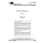
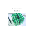
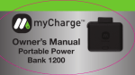
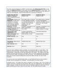
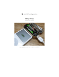
MintyBoost USB Charger Kit v3.0
MintyBoost USB Charger Kit
v3.0
Written By: Maker Shed
TOOLS:
PARTS:
Desoldering tool (optional) (1)
if you're prone to incorrectly soldering
parts
Flush diagonal cutters (1)
for cutting leads close to the PCB
Multimeter, or oscilloscope, (optional)
(1)
to check voltages and continuity
Solder, rosin core, 60/40 (1)
Use good quality solder; bad solder
causes bridging and cold solder joints.
Get at least a 1/2-pound spool so you
won't run out.
Soldering iron, with temperature control
(1)
One with a stand is best. Don't use a
"ColdHeat" soldering iron, they're not
suitable for delicate electronics work
and can damage the kit.
Third-hand tool, with magnifying glass,
(optional) (1)
makes things go much much faster
Tinsnips (1)
MintyBoost USB Charger Kit v3.0 (1)
Includes all of the following parts:
Boost converter (1)
LT1302CN8-5
Socket (1)
Capacitors, electrolytic (2)
for power supply
Capacitors, ceramic (2)
for bypass
Resistor, 1/8W 5% 3.3K, (R5) (1)
color-coded orange-orange-red-gold
resistors (2)
violet-green-black-red-brown
resistors (2)
yellow-white-white-red-brown
Diode, Schottky, (D1) (1)
1N5818 (or 1N5817, etc)
Power inductor (1)
at least 1A current capability
USB jack (1)
Battery holder, 2×AA (1)
MintyBoost printed circuit board (PCB)
(1)
© Make Projects
www.makeprojects.com
Page 1 of 18
MintyBoost USB Charger Kit v3.0
SUMMARY
This kit makes a small and simple, but very powerful USB charger for your MP3 player,
camera, cellphone, and just about any other gadget you can plug into a USB port to charge!
(See the user's manual for compatibility tests).
The charger circuitry and two AA batteries fit into an Altoids gum tin, and will run your iPod
for hours — in fact, for 2.5 times longer than you'd get from a 9V USB charger! You can use
rechargable batteries too.
The secret is in the high-efficiency power conversion circuit; it's up to 83% effective, so from
your two AA batteries you get 2.5 times more power than you'd get from a 9V battery!
The MintyBoost Kit Version 3 was designed in NYC by open-source hardware pioneer
Adafruit Industries, in partnership with MAKE and Maker Shed. It outputs 5V @ 500mA, and
it now works with iPhones and newer iGadgets. You can use any AA batteries (or even
upgrade to C or D cells for a mega battery pack).
In tests, the MintyBoost 3.0 gave the following results:
iPhone (all types): 3/4 full recharge
iPod video (tested, using alkaline batteries): 3hrs more video (1 full recharge)
iPod mini (tested w/rechargables): 26hrs more (1.5 full recharges)
iPod nano: 4 full recharges
iPod shuffle: 60 hours more, 5 full recharges!
This kit is suitable for beginners. Basic soldering is necessary but even if you've never
soldered before, it's pretty easy.
And the design is open source, so you can etch your own circuit board, breadboard the
circuit ... or simply buy the kit from the Maker Shed.
© Make Projects
www.makeprojects.com
Page 2 of 18
MintyBoost USB Charger Kit v3.0
Step 1 — Gather your tools and parts.
Check the tools and parts lists to verify you have all the parts necessary to make the kit.
Most importantly, confirm which version of the kit you have. Look at the packaging, and
the PCB — find that v3 that's on the back near the top!
Place the PCB in a vise, and turn on your soldering iron.
If you don't know how to solder, check out this excellent tutorial page.
Here's the schematic diagram that explains the circuit you'll solder. But don't worry, you
don't need to know how to read it — the following instructions will tell you all you need to
know to solder it.
© Make Projects
www.makeprojects.com
Page 3 of 18
MintyBoost USB Charger Kit v3.0
Step 2 — Solder resistor R5.
You're looking for a small oval tan thing with two wires (leads) and colored stripes. In the
case of resistor R5, the stripes are orange-orange-red, which indicates a 3.3K resistor.
This resistor is used to improve the high current capability of the boost converter chip and
is a new addition to the MintyBoost. It will go right in the middle of the printed circuit board
(PCB), over the silkscreened text that says R5.
Resistors are non-polar which means they don't have a direction: you don't have to worry
about putting it in backward because they work the same either way.
Bend the resistor leads down into the shape of a staple, and slip it into the holes in the top
of the PCB. Bend the little leads outward so that you can flip over the PCB and the resistor
will stay in place.
Now you'll solder! Place the flat of the soldering iron tip against the silver ring (pad) and
one of the wires (leads) of the resistor at the same time for 2 seconds. This will heat them
both up to 600°F–700°F. Then poke the end of the solder in there, so that it flows into the
hole and forms a solder joint.
Solder joints should be smooth and shiny and fill the entire pad, wicking up to the lead. You
shouldn't be able to wiggle the wire and have it move in the hole. Once you're happy with
your first solder joint, solder the second resistor lead.
Now use your diagonal cutters to clip the excess wire just above the end of the solder
joint. There should be almost no wire left sticking out.
© Make Projects
www.makeprojects.com
Page 4 of 18
MintyBoost USB Charger Kit v3.0
Step 3 — Solder resistors R2 and R4.
Next you'll solder the 75K 1% resistors R2 and R4. These are blue, with the following
stripe colors: violet-green-black-red-brown.
These resistors are very small and easy to confuse with the other blue resistors,
but the others have white and yellow stripes, so make sure these don't!
These resistors are used by Apple iPhones and such to determine what kind of charger is
connected.
Solder the resistors as you did the first one, one point at a time, checking your work.
Clip the long ends.
Step 4 — Solder resistors R1 and R3.
The 2 remaining resistors are
49.9K 1% resistors and have
yellow-white-white-red-brown
stripes. They go into slots R1 and
R3.
Solder them in and clip the leads
so they're nice and tidy.
© Make Projects
www.makeprojects.com
Page 5 of 18
MintyBoost USB Charger Kit v3.0
Step 5 — Add the ceramic capacitors.
The ceramic capacitors, C1 and C2
are symmetric/nonpolarized, so
they can go in either way.
Place them so their 2 legs (leads)
slide through the 2 holes in the
PCB (pads) and the capacitor sits
flat against the PCB.
C1 helps stabilize the output
voltage and filters out highfrequency noise, so the 5V output
is nice and smooth.
C2 is used to stabilize the internal
reference of the boost converter
chip. This keeps the chip stable so
it will generate a precise voltage.
(Ignore that black and white
diode in the photo; don't
place that yet ... just the two yellow
blobbies.)
Solder and clip the 2 ceramic caps.
© Make Projects
www.makeprojects.com
Page 6 of 18
MintyBoost USB Charger Kit v3.0
Step 6 — Solder the Schottky diode.
The Schottky diode D1 is part of
the boost converter. Essentially it
is used to make sure energy is
transferred in only one direction —
from the batteries to the USB port.
Diodes have a special
property that current can
only pass through them in one
direction — so it's important to
make sure they're not inserted
backwards.
Examine the diode and find the end
with a white stripe. This stripe
should match up with the
silkscreened image, which also has
a stripe on one end. In this image,
it is toward the top.
Solder and clip the diode.
Lookin' good! Make sure there are
no shorted wires or "dirty" solder
joints.
© Make Projects
www.makeprojects.com
Page 7 of 18
MintyBoost USB Charger Kit v3.0
Step 7 — Solder the IC socket.
The IC socket protects the chip and allows you to replace it if there are any problems.
Place the socket right over the 3.3K resistor. (The resistor shouldn't interfere as long as it
was soldered in properly.)
Make sure you place the socket so that the notch in its edge matches up with the
notch in the silkscreened image. In this image it's near the bottom. If you mess this
up, don't try to desolder the socket — instead just keep going and remember that it's
upside down later when it's time to install the chip.
The socket has short legs so it can be annoying to keep in the right position. Hold it in
place with one finger and "tack-solder" a corner.
Once that's done, solder in the remaining 7 pins. There's no need to clip.
© Make Projects
www.makeprojects.com
Page 8 of 18
MintyBoost USB Charger Kit v3.0
Step 8 — Solder the power inductor and capacitors.
The power inductor L1 is used by the DC/DC converter chip to store and convert power
from low voltages to high. Inductors are just a coil of wire, so they have no polarity and
can be placed either way.
The inductor may not sit perfectly flat, since the socket is in the way a bit. That's
OK. Just lean it over a little.
Solder in both leads and clip them short.
Next are the 2 electrolytic capacitors, C3 and C4. These are are commonly used for lowfrequency noise, often paired with a ceramic capacitor. Here they help smooth both the
input and output voltages, to keep them stable during the up-conversion.
Electrolytic capacitors are polarized and must be placed correctly or the circuit will not
work. The longer, positive (+) lead must go into the pad marked with a + as shown.
Solder in the 2 capacitors, then clip the wires.
© Make Projects
www.makeprojects.com
Page 9 of 18
MintyBoost USB Charger Kit v3.0
Step 9 — Solder the battery holder.
Next, solder in the 2xAA battery holder. The red wire goes to the hole marked + and the
black wire goes to the hole marked –.
Make sure you have them in right or you can damage the circuit!
Solder in the wires. If they're a little long you can clip them.
© Make Projects
www.makeprojects.com
Page 10 of 18
MintyBoost USB Charger Kit v3.0
Step 10 — Insert the boost converter IC.
Finally, carefully insert the boost converter chip.
Make sure the notch in the chip matches the notch in the socket.
If you soldered your socket backwards, make sure the notch faces the flat edge of the
PCB as shown.
Make sure the chip is seated all the way in and that the pins aren't bent.
© Make Projects
www.makeprojects.com
Page 11 of 18
MintyBoost USB Charger Kit v3.0
Step 11 — Time to test voltages!
Clean up your workbench so there are no little wire pieces that can short the kit (it's also
just nice to have a clean desk).
We like to put down a piece of paper to ensure there's no chance of damage. Then insert 2
fresh AA batteries — alkaline or rechargeable is OK.
Wait a few seconds and feel the battery and chip. Are they getting hot? If so, remove the
batteries and look over your work. The kit should not even get warm!
Use your multimeter to measure the voltage between the 2 outer pins of the USB
connector. (Read Adafruit's voltage tutorial here.)
You should get a bit higher than 5.0V but lower than 5.2V. If you get much higher than 5V,
first check that your multimeter has a fresh battery. Really! This is a really common
problem. If you get lower than 3V, remove the MintyBoost batteries and check your work.
Next, check between the rightmost pin and the second and third pin. These should both be
at just about 2.0V.
Once you're happy with these tests, remove the batteries from your kit and finish
assembling the kit!
© Make Projects
www.makeprojects.com
Page 12 of 18
MintyBoost USB Charger Kit v3.0
Step 12 — Solder the USB type A connector.
Next is the USB type A connector. This is the same connector that's on a computer, and
nearly all USB charging cables will plug into it. The connector should snap easily into
place.
The 2 large side connectors are used for mechanical strength. They keep the connector
attached solidly to the PCB, so make sure to use lots of solder or it will break off from use.
The 4 middle pins carry the power and data for USB. Solder in all 4.
© Make Projects
www.makeprojects.com
Page 13 of 18
MintyBoost USB Charger Kit v3.0
Step 13 — Test and troubleshoot.
Now is a good time to test your kit
— before you put it in the case.
Check that it charges your favorite
gadget and perhaps wait a few
minutes to make sure the battery
meter inches up.
If you're having trouble
getting the device to
recognize the MintyBoost as a
charger, it could be because it only
wants "USB spec" chargers. This
is easy to do with the MintyBoost
and always worth a shot, as it will
get most stuff up and running.
Here's how:
Remove the batteries from
your kit!
Use your soldering iron to heat
up the 2 middle USB pins at the
same time and blob on a bunch
of solder to short them together.
Now try again!
© Make Projects
www.makeprojects.com
Page 14 of 18
MintyBoost USB Charger Kit v3.0
Step 14 — Prepare the case.
OK, now you're ready to put it in the case. You could buy a tin of Altoids gum, but our kit
includes a tin that fits perfectly!
You'll need the MintyBoost kit, the empty tin, the 2 pieces of double-sided adhesive foam
tape, and a pair of tinsnips.
Cut 2 notches in one end of the tin (the short side), just about where the flat part ends and
the tin starts to round out.
Step 15
Now you want to bend the flap back and forth to break it off. If you're careful you can bend
it in more than out, which will make it round into the tin — one less sharp edge.
© Make Projects
www.makeprojects.com
Page 15 of 18
MintyBoost USB Charger Kit v3.0
Step 16 — Try a test fit.
Remove the kit batteries. Slide the board in first, then fit the battery pack in. Don't put the
batteries in for this test! The circuit board could short against the tin and destroy the
circuit!
Make sure the lid closes well, the USB connector fits well, and the notch is deep enough
so the jack doesn't interfere with the hinged lid.
© Make Projects
www.makeprojects.com
Page 16 of 18
MintyBoost USB Charger Kit v3.0
Step 17 — Assemble everything in the case.
Once you're happy with the fit, remove the electronics and put the double-sided sticky
foam tape on both the circuit board and the battery holder.
IMPORTANT: Make sure no pins or parts or leads are sticking out and can touch
the tin.
If necessary, use more foam, duct, or electrical tape to protect the circuit. Clip your leads
short so they don't poke through the foam. You can easily destroy the circuit by being
sloppy here.
Fit the circuit board in first and make sure it sits all the way to the end (it's a tight fit).
© Make Projects
www.makeprojects.com
Page 17 of 18
MintyBoost USB Charger Kit v3.0
Step 18 — Boost away!
You're done!
Plug in your favorite gadget's USB charging cable and boost away.
Remember that because the MAX756 chip uses virtually no power, you don't have to
remove the batteries to turn off the MintyBoost. Just plug and unplug devices whenever
you want.
Adafruit has also documented the process of designing this kit, in case other people interested in
designing and making kits are interested in learning how to start selling their own kits!
This document was last generated on 2013-01-15 03:24:38 PM.
© Make Projects
www.makeprojects.com
Page 18 of 18