1
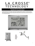
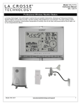
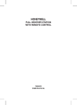
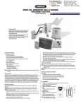
Professional Wireless Weather Station
WS-1517 | Quick Setup Guide
Carefully open the package and check that the following contents are complete:
Wind Sensor
TS805
•
•
•
Requires 4 mounting
screws
Requires 2 AA batteries
(not included)
1 hex key wrench
Wind Sensor also Protected under
U.S. Patent: 6,761,065; RE42,057
Rain Sensor
TS906
•
•
Requires 4 mounting
screws
Requires 2 AA batteries
(not included)
Thermo-Hygro Sensor
TS21
•
•
Wall mount adapter
Requires 2 AAA batteries
(not included)
Wireless Display
WS-1517
•
•
7.5 V AC/DC
adapter
(included)
4 AA batteries
(not included)
All items, including Wind Sensor, are Protected under U.S. Patents:
5,978,738; 6,076,044; & 6,597,990
Setup Instructions Step-by-Step
IMPORTANT: Make sure to observe the correct polarity when inserting batteries (not included). The "+" markings on the batteries must line
up with the diagrams inside the battery compartments. Inserting the batteries incorrectly may result in permanent damage to the
weather station. During the setup process, place the wireless display and the outdoor sensors on a surface with 5-10 feet between each
sensor and the display.
Batteries: We recommend using Alkaline batteries for the remote sensors and the weather station when temperatures are above 32°F
(0°C). We recommend using Lithium batteries for the remote sensors when temperatures are below 32°F (0°C).
Note: Setup all three sensors and allow them to run for at least two minutes before powering the weather station. Ensure all sensor
readings are received to the weather station before mounting sensors outside.
STEP 1: Complete initial setup on a table with all components within 10 feet of each other.
STEP 2: Wind
Wind Cups
1. With a flashlight, look into the mounting hole of the wind cups.
2. Check that the set screw is backed off appropriately, not obstructing the opening.
3. Place the wind cups over the axle shaft of the wind sensor and gently slide them into place.
4. Use the hex key wrench tool provided to tighten the small set screw inside the cups.
5. Test to assure the wind cups are securely mounted on the anemometer shaft and spin freely
Battery installation
1. Remove four (4) screws from the battery compartment.
2. Open the battery compartment and install 2 AA Alkaline batteries (not included) matching the polarities shown.
3. Replace the battery compartment door and secure the screws.
STEP 3: Thermohygro
1. Install 2 AAA Alkaline batteries (not included) matching the polarities shown in the battery compartment.
2. Replace the battery compartment door.
STEP 4: Rain
1. Unlock the funnel-shaped top on the rain sensor by turning both knobs on the sides in a counter-clockwise direction.
2. Lift the funnel-shaped top off the rain sensor bucket.
3. Remove seven (7) small screws from the battery compartment cover.
4. Insert 2 AA Alkaline batteries (not included), matching the polarities as shown in the battery compartment.
1
5.
6.
Replace the battery compartment door and secure the screws.
Insert the funnel-shaped top into the rain sensor bucket. Turn the knobs clockwise to secure it.
Allow all sensors to operate for two minutes before starting the weather station.
STEP 5: Weather Station
1. Connect 7.5 V A/C adapter provided to the weather station and plug into to the wall power outlet.
Note: The A/C adaptor connection is required for automatic backlight control function.
When the weather station operates on battery power alone, the auto backlight control function is
disabled.
2. Connect the table stand to the back of weather station when placing on a table or other horizontal
surface.
3. Open the battery compartment door on the back of the main weather station.
4. Insert 4 AA batteries according to the polarities shown and replace the battery compartment door
(optional).
5. Once the weather station is powered, the display will show all available LCD segments for a moment.
IMPORTANT: Do not press any buttons during the setup process which takes 5-15 minutes. During this time, the weather
station will show the pressure and weather icon and inHg (inches of mercury) flashing. Setup is completed when the
weather station shows default settings for pressure and altitude (sea level), indoor/outdoor temperature and humidity, wind
and rain readings, etc.
STEP 6:
Set Wind Direction
1. Wait until all the sensor readings are received by the weather station.
2. Manually point the wind direction vane to the North (use a compass or map if necessary).
3. Press the SET opening located inside battery compartment with a paper clip or similar tool. This will set the
local wind direction to North. Only press once. Continued presses of SET alternately toggles wind direction
between the factory defaults preset or manual set direction.
Note: Repeat this procedure every time when changing the batteries.
4. Watch for the next update to ensure the direction changed to North.
Step 7: Program the weather station. See “Program Menu” below.
Note: This weather station has been designed to work right out of the box 10-15 minutes after power setup. Language and City Code are
the only required items to set in the program menu. When the WWVB radio-controlled time signal is received, the time and date will be set
according to city code selected. There are additional operational details and suggestions for custom settings and alarms including:
•
The time alarms
•
The temperature alerts
•
Daily rainfall alerts
•
Wind alerts
•
Local Pressure
See “Custom Settings” for details on the optional settings.
LCD Screen
Pressure
and
Weather
Temperature
and Humidity
Wind
Clock and
Alarm
Rain
2
Program Menu
Press the UP or DOWN arrow button until the clock and alarm icon flashes. The SET button will move through the program
menu. The UP or DOWN arrow button will change a value.
1.
Hold the SET button until the day of week language abbreviation ENG will flash. Press the UP or DOWN arrow button to select the
desired language for day of the week in English (ENG), German (GER), French (FRE), Italian (ITA), Spanish (SPA) or Dutch (DUT).
2. Press the SET button to confirm and move to select the city code for your time zone.
3. City Code LAX (Los Angeles) will flash. Use the UP and DOWN button to select a city code in your time zone. Refer to table in the
back of this quick setup guide, for a list of available cities.
4. Press the SET button to confirm the city selection. The year will flash 2005.
5. Press the UP or DOWN button to select the correct year.
6. Press the SET button to confirm year selection. The month will flash.
7. Press the UP or DOWN button to select the correct month.
8. Press the SET button to confirm selection. The numeric date will flash.
9. Press the UP or DOWN button to select the correct date.
10. Press the SET button to confirm selection. M/D or D/M will flash.
11. Press the UP or DOWN button to select the correct order of month & year. (M…D)
12. Press the SET button to confirm selection. 12H will flash.
13. Press the UP or DOWN button to select either 12 hour (AM/PM) or 24 hour (24:00) time format
14. Press the SET button to confirm selection. The Hour will flash.
15. Press the UP or DOWN button to select the correct hour.
16. Press the SET button to confirm selection. The minutes will flash.
17. Press the UP or DOWN button to select the correct minutes.
18. Press the SET button to confirm selection and to complete the initial programming for your weather station.
19. After programming is completed, the weather station will show the default clock and alarm window.
Note: If you do not complete this sequence your entries will be lost.
Note: Press and hold SET anytime during the setup to return to normal clock and alarm window and all previous settings will be cancelled.
Positioning Sensors Outside
•
•
•
•
•
Each sensor reads to the weather station independently.
Consider the location of the weather station in the house and in relation to each sensor outside.
The transmission range is 100 ft (30 m) open air.
Obstacles such as walls, concrete and large metal objects can reduce the range by one-half.
Place sensors and weather station in desired locations, and wait approximately 15 minutes before permanently mounting to ensure
that there is proper reception.
Wind
•
•
•
For most accurate wind readings, mount the wind sensor as the highest item in the area with a 50 foot clearance in all directions.
Cup should be on the bottom.
Use 4 screws to mount the wind sensor vertically on a piece of wood about 3 inches wide.
Rain
•
•
•
•
•
•
Make sure that the rain sensor is level–look inside, there is a built-in level. Make sure the bubble is
centered.
Place the protective screen over the top to protect the rain sensor from the debris.
Where practical, mount the rain sensor in place with wood screws (not included).
Make sure that the rain sensor is in open area where precipitation falls directly into the sensor’s
bucket, ideally 3-6 feet above the ground.
Note: The rain sensor will need to be cleaned of debris on a regular basis. Mount in an accessible area.
The rain sensor should be placed in an open area away from the walls, fences, trees and other coverings
which may reduce the amount of rain falling into the bucket. Additionally, trees and rooftops may be sources
of pollen and debris that may clog the rain sensor.
To avoid the rain shadow effects, place the rain sensor horizontally, on the distance corresponding about
two to four times the height of any nearby obstruction.
Thermohygro
•
•
•
•
•
•
•
The remote thermohygro sensor should be placed in the area with a free air circulation and sheltered from direct sunlight and
an extreme weather conditions.
While the thermohygro sensor is weather resistant, avoid submersion in water or snow.
We recommend that you mount the outdoor temperature sensor on an outside North-facing wall.
The remote thermohygro sensor can stand vertically on a flat surface or mounted on the wall in vertical position
Use screws when mounting the thermohygro sensor on the wall
Avoid placing the thermohygro sensor near sources of heat such as chimneys and heating elements.
Avoid areas that collect or radiate heat from the sun, such as metal, brick/concrete structures, paving or patio decks.
Weather Station
•
•
•
•
•
Make sure that the weather station is locating within the operating range of all remote sensors.
Mount the remote sensors within the line of sight of the weather station.
Transmission range may be affected by trees, metal structures and electronic appliances.
Test reception before permanently mounting all the remote sensors.
Mount near an exterior wall with the front or back facing toward Ft. Collins, Colorado for best WWVB reception.
3
Avoid placing the weather station in the following areas:
•
Direct sunlight and surfaces emitting and radiating heat, such as heating ducts or air conditioners.
•
Areas with interference from the wireless devices (such as cordless phones, radio headsets, baby listening devices, etc.) and
electronic appliances.
Custom Settings
You weather station will function without additional settings. These custom settings allow more detailed settings and alerts. We will take
each section individually.
Pressure and Weather
Note: Wait at least 15 minutes after initial set up to view pressure or altitude information.
Press the UP or DOWN button arrow buttons on the weather station until the pressure and weather icon begins to flash, in the
left corner of the upper display.
The weather station will display (local) barometric pressure, sea level pressure, and weather forecast and moon phases. Historical statistics
can also be viewed, including the sea-level pressure for the past 24 hours, moon phase for the past and following 39 days, and a selectable
bar-chart for viewing pressure/temperature & humidity history. Pressure may be displayed inHg (English), hPa/mBar (scientific) or mmHg
(metric). Altitude is displayed in meters or feet.
Pressure and Altitude Information
Pressure and altitude work together, so only set one. The weather station will measure local pressure and calculate the other two
parameters based on the Local Pressure.
Sea Level Pressure and Altitude are interdependent.
•
Adjust altitude and the weather station will calculate sea level pressure.
•
Adjust sea level pressure, and the weather station will automatically calculate altitude.
•
You can only adjust one of the two–either sea level barometric pressure or altitude.
Press and release the SET button to alternate between
•
Sea Level Pressure
•
Local Pressure
•
Local Altitude settings
The default settings are: inHg (Inches of Mercury), and 33 feet. These setting can be changed to local readings.
Local Pressure reflects pressure changes at your specific location (house). The local altitude/elevation must be programmed according
to GPS readings, internet, etc.
Sea Level Pressure reflects pressure changes in your surrounding metro area. The Sea level barometric pressure value can be adjusted
according to the local metro area weather information (Sources–local TV, radio station, etc.).
Changing or Setting Sea Level Pressure
1.
2.
3.
4.
5.
6.
7.
Press the SET button until the local pressure with the word “SEA LEVEL” is displayed.
Hold the MEMORY button until the pressure unit is flashing, inHg, mmHg or hPa/mBar
Set the pressure units with the UP or DOWN arrow buttons
Press the MEMORY button to confirm your selection
Hold the SET button until the pressure digits flash.
Set the sea level pressure using the UP or DOWN buttons to adjust the pressure value. Hold the UP or DOWN arrow buttons for faster
digits advancement
Press the SET button to confirm your selection.
Changing or Setting Altitude
1.
2.
3.
4.
5.
6.
7.
Press the SET button until the local altitude value will be displayed
Hold the MEMORY button until the altitude unit is flashing, feet or meters.
Press the UP or DOWN button arrow buttons to set altitude in feet or meters
Press MEMORY button once to confirm your selection
Hold the SET button until the altitude digits are flashing.
Set the altitude value with the UP or DOWN arrow buttons. Hold the UP or DOWN arrow button for faster digits advancement
Press the SET button to confirm your selection.
View the Sea Level Pressure History
•
•
•
From any mode, press the HISTORY button.
When the SEA LEVEL is displayed, press and release the HISTORY button repeatedly to view the sea level pressure history for the
past 24 hours, in hour intervals.
If no buttons are pressed for 5 seconds, the weather station will automatically exit history mode and return to the Pressure and
Weather Forecast mode.
View the Pressure, Temperature and Humidity Bar Charts
The pressure bar graph shows barometric pressure variations over the past 24 hours. This is very useful for understanding the Barometric
trends that are used in weather forecasting. Each bar icon represents 0.06 inHg. Alternatively, the bar chart can be used to display 24 hour
trend data for Sea Level Pressure, outdoor temperature or outdoor humidity (channel 1 only).
4
•
•
•
•
Select the Pressure and Weather Forecast window.
Hold the ALARM/CHART button to toggle the bar chart title (right bottom corner).
Alternate between Pressure, Outdoor Temperature (thermometer icon) and Relative Humidity (dew drop icon).
The single bar on the far right indicates rising or falling trend.
View the Moon Phase History
The weather station indicates the current moon phase. Previous moon phases are selected with the minus sign showing: -1 day, -2 days,
etc. Future moon phase are selected based on the days ahead: +1 day, + 2 days, etc. up to 39 days.
•
•
•
•
Select the Pressure and Weather Forecast display.
Press and release the MEMORY button, and + 0 days will flash.
Press the UP or DOWN arrow buttons selecting from today’s date a future (+) or
past (-) days and the corresponding moon phase will be displayed. Hold either
arrow button for a quick advance.
Press the MEMORY button to exit
Weather Forecast Icons
The weather forecasting feature is estimated to be 70% accurate. The weather forecast is based solely upon the change of air pressure
over time. The icons are predicting 12-24 hours in the future, not current conditions. It may be sunny out your window, but the pressure is
falling so the forecast station will show clouds with rain icon. The SUNNY icon indicates clear weather, even when displayed during the
night-time.
Temperature and Humidity
The weather station supports indoor temperature & humidity and up to five
remote thermohygro sensors (1 remote sensor is included).
Note: At this time, there are no additional thermohygro sensors available for
purchase.
•
Temperature can be displayed in either Fahrenheit (ºF) or Celsius (ºC).
•
The weather station calculates indoor comfort level--Wet, Comfort or Dry.
•
Dew Point based on temperature & humidity readings.
•
Temperature alarms can be set on the weather station.
•
Thermohygro sensor remote battery status is monitored on the main weather station.
View Temperature and Dew Point
With temperature and humidity icon flashing, press the SET button to alternate between temperature and relative humidity or
dew point and relative humidity.
Set Temperature Alarm
1.
2.
3.
4.
In the temperature and humidity mode, press and release the ALARM/CHART button once selecting the desired alarm limit–-Upper or
Lower
Hold the ALARM/CHART button until the temperature alarm icon starts flashing.
Use the UP or DOWN arrows to select the temperatures. Press and hold either button for fast digits advance.
Press the ALARM/CHART button to confirm selection and return to the Temperature Alarm selection screen.
Note: The temperature alarms have a 1°F (0.5 ºC) deviation to prevent false alarms due to small temperature fluctuations.
Temperature has to fall below (or above) the programmed level(s) to activate the alert.
Select Fahrenheit or Celsius
•
With temperature and humidity icon flashing, hold the SET button to alternate between temperature in Fahrenheit (ºF) or Celsius (ºC).
Disable the Temperature Alarm
1.
2.
In the Temperature and Humidity Mode, press and release the ALARM/CHART button once to select the high or low temperature
alarm.
With the alarm icon showing, press and release the UP or DOWN buttons to turn the alarm OFF. When the temperature shows with the
high or low alarm icon, the alarm is active.
Max/Min Records
View: With the temperature & humidity icon flashing, press the MEMORY button to recall a current temperature and humidity, minimum
temperature and humidity or maximum temperature and humidity at the remote location.
Reset: Hold the MEMORY button for five seconds to clear all MIN/MAX readings.
5
Rain Window
The weather station records the total amount of the rainfall for:
•
Last hour
•
24 hours
•
Past day
•
Past week
•
Past month
The rainfall can be displayed in inches or mm. There is a daily
rainfall alert that can be programmed.
Rain Statistics
View: With the rain icon flashing Press either SET or MEMORY button to recall a rain statistics for the past hour, past 24 hours,
yesterday, past week or past month.
Note: Last Hour rainfall value is displayed as a rate of rain in either “inch/hr.” or “mm/hr.”
Reset: With the rain icon flashing, press and hold the MEMORY button to reset all rainfall statistics.
Setting Rain Display; inches or mm
•
With the rain icon flashing, press and hold the SET button to toggle rainfall units of measure between mm and inches.
24 hour Rainfall Alert
Set
1.
2.
3.
Daily Rainfall Alert
With the rain icon flashing, press ALARM/CHART button to display the rainfall alert.
Hold ALARM/CHART button until the rainfall alert ALARM HI will flash.
Set the desired value for the Rainfall Alert by using UP or DOWN arrow button. Press and hold either button for fast digits advance.
Alert Off
1. With the rain icon flashing, press the ALARM/CHART button to display either the current rainfall statistics or the daily rainfall alert with
ALARM HI displayed.
2. Press the UP or DOWN arrow button to enable or disable it.
3. If the alert is disabled, the OFF will be displayed.
4. Press ALARM/CHART button to confirm selection and the weather station will return to the rainfall alert display.
Wind Window
•
•
•
Wind direction is shown by compass points (i.e. NW) or in bearings starting from north (i.e. 22.5º).
The weather station records the maximum wind speed and gusts collected during the day. Wind speed and gust alerts can be
programmed.
Wind sensor temperature or wind chill are selectable
Average wind speed (over the past 10 minutes) is displayed
Wind Gust
Wind Display
1.
2.
Press the UP or DOWN button until the wind icon on the display flashes.
Press and release the SET button to alternate between:
•
Wind chill with direction in bearings
•
Wind chill with direction in compass points
•
Wind sensor temperature & wind direction in compass points
•
Wind sensor temperature and wind direction in bearings
Select Wind Speed in km/h, mph, m/s or knots
With the wind icon flashing, hold the SET button to set the wind speed units in:
•
km/h (kilometers per hour)
•
mph (miles per hour)
•
m/s (meters per second)
•
knots
Wind MAX/MIN
View: With the wind icon flashing, press and release the MEMORY button to view:
•
Current wind speed
•
Daily maximum wind speed
•
Gust speed
•
Daily maximum gust speed
Reset: With the wind icon flashing, hold the MEMORY button to reset all wind statistics.
Set Wind Alerts
The weather station will allow you to set Wind Speed Hi alert and Wind Gust Hi alert.
6
1.
2.
3.
4.
With the wind icon flashing, press ALARM/CHART button to select the desired alarm.
Hold the ALARM/CHART button until alert and corresponding icon will flash.
Set the alert using UP or DOWN arrow button. Press and hold either button for fast digits advance.
Press ALARM/CHART button to confirm your selection and return to the wind alert selection screen.
Disable the Wind Alert
•
To disable wind alert when it is displayed after pressing ALARM/CHART button, press the UP or DOWN button arrow button. OFF will
be displayed instead of previously set alarm time.
Note: The wind speed alert is set at 5 mph default and the wind gust alert is set to 7 mph default to prevent false alerts from small
fluctuations.
Clock and Alarm Window
With the clock and alarm icon flashing, press the SET button to switch what is displayed:
•
Local Time
•
City code
•
Seconds
•
Date
•
UTC time
The program menu (above) can be accessed in the clock and alarm window.
Time Alarm
There are two time alarms available on the weather station:
•
Weekday alarm (W)
•
Single alarm (S)
The weekday alarm will repeat Monday through Friday at the time set.
The single day alarm is only for this one specific day and will not activate on subsequent days.
Note: The snooze duration for listed alarms can also be programmed up to 15 minutes.
Set Time Alarms
1.
2.
3.
4.
5.
6.
7.
8.
9.
With the clock and alarm icon flashing, press the ALARM/CHART button to select the desired alarm.
Hold the ALARM/CHART button and the hour will flash.
Set the alarm hour using UP or DOWN arrow button. Press and hold either arrow button for quick digit advance.
Press the ALARM/CHART button to confirm selection then the minutes will flash.
Set the alarm minutes using UP or DOWN arrow button. Press and hold either arrow button for quick digit advance.
Press the ALARM/CHART button to confirm selection.
Set a Snooze interval using UP or DOWN arrow button. Press and hold either arrow button for quick digit advance.
Note: both alarms share same snooze time duration
Press the ALARM/CHART button to confirm your selection.
When programming is completed, the weather station will return to the alarm selection screen.
Enable/Disable Time Alarms
1. Press the ALARM/CHART button to display the weekday alarm or single day alarm time. If these alarms are not set, the abbreviation
OFF will be displayed.
2. To enable or disable any of these alarms, press the UP or DOWN button arrow button.
3. Press the ALARM/CHART button to confirm your setting
Note: Press the SET button anytime during alarm programming mode to return to the default clock display.
Snooze function
When the alarm sounds, press the LIGHT/SNOOZE button to activate the snooze feature for the interval set.
Note: Alarm will automatically “snooze” if no buttons are pressed after the alarm sounds for 2 minutes. This will occur three times only.
WWVB Radio-Controlled Time Reception
The radio controlled clock searches for, and periodically synchronizes to, the NIST (National Institute of Standards and Technology) atomic
clock signal transmitted from Ft. Collins, Colorado, throughout the entire continental United States.
•
During night-time hours, atmospheric conditions improve radio signal reception. A single daily reception is sufficient enough to keep
the clock accuracy within milliseconds.
•
The weather station should be positioned 6 feet (2 meters) from interference sources such as a TV, computer, microwave, etc.
•
The signal reception is weakened within concrete walls found in basements or office buildings. Place the weather station near the
window for best reception.
•
It takes between 24 and 72 hours for the clock to receive an atomic time signal reception
Once the atomic time signal is received, the date and time will be set automatically, and the icon will appear. The weather station is
programmed to search for the atomic time signal daily each hour between 1:00 am and 4:30 am. Once the time signal has been
successfully received, the time and date will be updated automatically.
Manual Signal Search
With the clock and alarm icon flashing, hold the UP arrow for three seconds to manually
search for the WWVB signal. A triangular tower icon will start flashing next to the clock icon.
Searching
Strong Signal
Weak Signal
No signal
7
Backlight Options
When operating with the optional A/C power cord, the weather station backlight can be turned ON, OFF or automatic (depending on light
conditions).
•
AUTO: the backlight will be off in when there is adequate light, and will come on automatically in low light conditions.
•
ON: the backlight will be on constantly when using A/C power.
•
OFF: the backlight will remain off unless the LIGHT button is pressed.
Note: For continuous backlight control the optional A/C adaptor (not included) must be plugged in.
Backlight sensor sensitivity can be adjusted to high or low using the switch, located on the back of the weather station.
When operating on battery power alone, the backlight can be activated for three seconds by pressing the LIGHT button
on top of the weather station.
Remote Sensor Status Icon
The wave icon above the channel 1 display shows the connection status of the remote sensor.
Searching
Strong
No Signal
Activate Search for Remote Sensors
•
Hold the DOWN arrow button for 4–6 seconds to activate a search for all remote sensors.
Normally, the weather station will automatically find and display measurement results from the remote sensors. Occasionally other radio
transmission sources (TV, cordless or cell phones, etc.) can interrupt the sensor signal.
Memory Reset Procedure
Note: This will completely reset all of the stored memory.
1. Hold SNOOZE and UP buttons for 4 seconds so the backlight will flash.
2. Press the SET button which will clear the memory–the weather station will start beeping with a 1 second delay.
3. Wait until the beeping stops.
4. Disconnect weather station from the A/C adapter. Remove batteries from the back or the weather station (optional) if installed.
5. Wait at least 10 seconds, and then reinsert the A/C adapter and batteries.
IMPORTANT: Do not press any buttons during the setup process which take 5-15 minutes. During this time the weather station will
show the pressure icon and inHg (inches of mercury) flashing. Setup is completed when the weather station shows default settings for
pressure and altitude (sea level), indoor/outdoor temperature and humidity, wind and rain readings, etc.
6. Follow the program menu to set language and city code then any custom settings desired.
Changing Batteries
The battery status of each remote sensor is checked every hour. If the low battery indicator lights up, replace the batteries in the
corresponding sensor.
•
Do Not Mix Old and New Batteries
•
Do Not Mix Alkaline, Standard, Lithium or Rechargeable Batteries
Weather Station
With A/C power cord: Connect the optional 7.5V A/C adaptor to the weather station to avoid losing any data.
•
Remove the battery compartment door at the back and replace all batteries.
•
Replace the battery compartment door.
Without A/C power cord:
•
Remove the battery compartment door at the back and replace all batteries.
•
Replace the battery compartment door.
•
Do not press any buttons during the setup process, which takes 5-15 minutes. During this time, the weather station will show the
pressure icon and inHg (inches of mercury) flashing. Setup is completed when the weather station shows default settings for pressure
and altitude (sea level), indoor/outdoor temperature and humidity, wind and rain readings, etc.
•
Set language and city code.
Remote Sensor Batteries
•
•
•
Replace the batteries following the setup instructions for the corresponding sensor.
When the batteries are properly installed, the remote sensor will resume sending signals to the weather station.
Hold the DOWN arrow button for 4–5 seconds on the weather station to search for the remote sensors.
Care and Maintenance
•
•
•
•
•
•
Do not immerse the sensors or weather station in water.
Do not clean the sensors or weather station with abrasive or corrosive materials that might scratch plastic parts or corrode electronic
circuits.
Do not subject the sensors or weather station to excessive force, shock, dust, temperature, or humidity, which may result in
malfunctions, shorter lifespan, damaged batteries, and damaged parts.
Do not tamper with the product’s internal components. Doing so will invalidate the warranty and may cause damage.
The product contains no user-serviceable parts.
Read the user's manual thoroughly before operating the product.
8
Specifications
Radio Frequency:
RF Reception range:
433 MHz
100 feet (30 m) open air
Barometric Pressure
Measuring Range:
Resolution:
Operating range:
Sampling interval:
Sea level Altitude Compensation Range:
14.75 inHg to 32.44 inHg (500 hPa to 1100hPa); (374.5 mmHg to 823.8 mmHg)
0.003 inHg (0.1 hPa, 0.08 mmHg)
100 feet (30 m) open air
20 minutes
-657 ft. to 16404 ft. (-200m to +5000 m)
Temperature (Indoor)
Operating Range:
Resolution:
Sampling Interval:
14.2°F to 140°F (-9.9°C to 60°C)
0.2°F (0.1°C)
10 seconds
Temperature (Remote)
Range:
Resolution:
Transmitting Interval:
-40°F to 176°F (-40°C to 80°C)
0.2°F (0.1°C)
around 47 seconds
Humidity (Indoor)
Operating Range:
Resolution:
Sampling Interval:
0% to 99%
1%
10 seconds
Humidity (Remote)
Operating Range:
Resolution:
Sampling Interval:
Transmitting Interval:
Operating range:
0% to 99%
1%
10 seconds
around 47 seconds
100 feet (30 m) open air
Wind Direction
Range:
Resolution:
Transmitting interval:
Operating Range:
0° to 360°
22.5°
33 seconds
100 feet (30 m) open air
Wind Speed
Range:
Resolution:
Starting Threshold:
Wind/Gust Speed Update Interval:
Wind/Gust Sampling Interval:
Operating Range:
0 to 199.9mph (199.9 Km/h, 173.7 Knots, 89.3 m/s)
0.1mph (0.16 Km/h)
3mph (4.8 Km/h)
33 seconds
11 seconds
100 feet (30 m) open air
Rainfall
1h/24h/yesterday range:
Last week/ last month range:
Resolution:
Transmitting Interval:
Operating Range:
0 to 78.73 inch (0 to 1999.9 mm)
0 to 787.3 inch (0 to 19999 mm)
0.03 inch (0.6578 mm)
183 seconds
100 feet (30 m) open air
Power (8 AA Batteries, 2 AAA Batteries)
Weather Station
TS21Thermohygro sensor:
TS805 Anemometer:
TS906 Rain Sensor:
7.5V AC power adaptor (included) or 4 x AA 1.5V batteries (not included)
2 x AAA 1.5V batteries (not included)
2 x AA 1.5V batteries (not included)
2 x AA 1.5V batteries (not included)
Battery Life (Alkaline)
Weather Station
TS21 Thermohygro sensor:
TS805 Anemometer:
TS906 Rain Sensor:
2 months (without AC adapter)
Over 12 months
2 years
2 years
Dimensions
Weather Station
TS21 Thermohygro sensor:
TS805 Anemometer:
TS905 Rain sensor:
7.31 (L) x 5.39 (H) x 1.26 (D) inches (185.8 (L) x 136.9 (H) x 32 (D) mm)
2.37 (L) x 4 (H) x 1 (D) inches (60 (L) x 101 (H) x 25 (D) mm)
19.16 (L) x 19.16 (H) x 15.35 (D) inches (486.6 (L) x 486.6 (H) x 390 (D) mm)
6.49 (L) x 6.89 (H) x 4.72 (D) inches (165 (L) x 175 (H) x 119 (D) mm)
9
CITY CODES
Time zone is based on a city code. Select a city near you, in the same time zone.
Pacific, Mountain, Central and Eastern time zones will display a map of the USA.
North America
Time
Zone
Offset
Code
Other
Countries
Las Vegas, NV
-8
LAS
Addis, Ababa, Ethiopia
La Angeles, CA
-8
LAX
Adelaide, Australia
Portland, OR
-8
PDX
Ankara, Turkey
Time
Zone
Offset
Code
Other
Countries
3
ADD
Kingston, Jamaica
Time
Zone
Offset
Code
-5
KIN
9.5
ADL
Osaka, Japan
9
KIX
2
AKR
Kuala Lumpur, Malaysia
8
KUL
LIM
San Diego, CA
-8
SAN
Algiers, Algeria
1
ALG
Lima, Peru
-5
Seattle, WA
-8
SEA
Amsterdam, Netherlands
1
AMS
Lisbon, Portugal
0
LIS
San Francisco, CA
-8
SFO
Stockholm, Arlands, Sweden
1
ARN
London, England
0
LON
LPB
San Jose, CA
-8
SJC
Asuncion, Paraguay
-3
ASU
La Paz, Bolivia
-4
Vancouver, Canada
-8
VAC
Athens, Greece
2
ATH
Liverpool, England
0
LPL
Vancouver BC, Canada
-8
YVR
Bucharest, Romania
2
BBU
Lyon, France
1
LYO
Denver, CO
-7
DEN
Barcelona, Spain
1
BCN
Madrid, Spain
1
MAD
El Paso, TX
-7
ELP
Belgrade, Yugoslavia
1
BEG
Melbourne, Australia
10
MEL
Phoenix, AZ
-7
PHX
Beijing, China
8
BEJ
Milan, Italy
1
MIL
Calgary Alberta, Canada
-7
YYC
Berlin, Germany
1
BER
Manila, Phillipines
8
MNL
Austin, TX
-6
AUS
Birmingham, England
0
BHX
Moscow, Russia
3
MOW
Birmingham, AL
-6
BHM
Bangkok, Thailand
7
BKK
Marseille, France
1
MRS
Nashville, TN
-6
BNA
Brisbane, Australia
10
BNE
Munich, Germany
1
MUC
Chicago, IL
-6
CGX
Bordeaux, France
1
BOD
Montevideo, Uraguay
-3
MVD
Chihauhua, Mexico
-6
CUU
Bogata, Columbia
-5
BOG
Naples, Italy
1
NAP
Dallas, TX
-6
DAL
Bremen, Germany
1
BRE
Nairobi, Kenya
3
NBO
Houston, TX
-6
Hou
Brussels, Germany
1
BRU
Nanjing (Nanking), China
8
NKG
Memphis, TN
-6
MEM
Buenos Aires, Argentina
-3
BUA
Odessa, Ukraine
2
ODS
Mexico City, Mexico
-6
MEX
Budapest, Hungary
1
BUD
Omaha, Nebraska, USA
-6
OMA
Milwaukee, WI
-6
MKE
Cairo, Egypt
2
CAI
Oslo, Norway
1
OSL
Minneapolis, MN
-6
MSP
Caracas, Venezuela
-4
CCS
Paris, France
1
PAR
New Orleans, LA
-6
MSY
Calcutta, India (as Kolkata)
5.5
CCU
Perth, Australia
8
PER
Oklahoma City, OK
-6
OKC
Cordoba, Argentina
-3
COR
Prague, Czech Republic
1
PRG
San Antonio, TX
-6
SAT
Copenhagen, Denmark
1
CPH
Panama City, Panama
-5
PTY
St Louis, MO
-6
STL
Cape Town, South Africa
2
CPT
Rangoon, Myanmar
6.5
RGN
Atlanta, GA
-5
ATL
New Dehli, India
5.5
DEL
Rio de Janeiro, Brazil
-3
RIO
Boston, MA
-5
BOS
Dakar, Sengal
0
DKR
Reykjavik, Iceland
0
RKV
Baltimore, MD
-5
BWI
Dublin, Ireland
0
DUB
Rome, Italy
1
ROM
Cleveland, OH
-5
CLE
Durban, South Africa
2
DUR
Santiago, Chile
-4
SCL
Columbus, OH
-5
CMH
Kinshasa, Congo
1
FIH
Shanghai, China
8
SHA
Cincinnati, OH
-5
CVG
Frankfurt, Germany
1
FRA
Singapore, Malasia
8
SIN
Washington, DC
-5
DCA
Glasgow, Scotland
0
GLA
Sofia, Bulgaria
2
SOF
Detroit, MI
-5
DTW
Guatemala City, Guatemala
-6
GUA
Sao Paulo, Brazil
-3
SPL
Havana, Cuba
-5
HAV
Hamburg, Germany
1
HAM
Salvador, Brazil
-3
SSA
Indianapolis, IN
-5
IND
Helsinki, Finland
2
HEL
Sydney, Australia
10
SYD
Jacksonville, FL
-5
JAX
Hong Kong, China
8
HKG
Toykyo, Japan
9
TKO
Miami, FL
-5
MIA
Irkutsk, Russia
8
IKT
Tripoli, Libya
2
TRP
New York, NY
-5
NYC
Jakarta, Indonesia
7
JKT
Vienna, Austria
1
VIE
Philadelphia, PA
-5
PHL
Johannesburg, South Africa
2
JNB
Warsaw, Poland
1
WAW
Pittsburgh, PA
-5
PIT
Zurich, Switzerland
1
ZRH
Tampa, FL
-5
TPA
Montreal, Quebec, Canada
-5
YMX
Ottawa, Ontario, Canada
-5
YOW
Toronto, Ontario, Canada
-5
YTZ
10
Warranty Information
La Crosse Technology, Ltd provides a 1-year limited warranty on this product against manufacturing defects in materials and workmanship.
This limited warranty begins on the original date of purchase, is valid only on products purchased and used in North America and only to the original
purchaser of this product. To receive warranty service, the purchaser must contact La Crosse Technology, Ltd for problem determination and service
procedures. Warranty service can only be performed by a La Crosse Technology, Ltd authorized service center. The original dated bill of sale must
be presented upon request as proof of purchase to La Crosse Technology, Ltd or La Crosse Technology, Ltd’s authorized service center.
La Crosse Technology, Ltd will repair or replace this product, at our option and at no charge as stipulated herein, with new or reconditioned parts or
products if found to be defective during the limited warranty period specified above. All replaced parts and products become the property of La
Crosse Technology, Ltd and must be returned to La Crosse Technology, Ltd. Replacement parts and products assume the remaining original
warranty, or ninety (90) days, whichever is longer. La Crosse Technology, Ltd will pay all expenses for labor and materials for all repairs covered by
this warranty. If necessary repairs are not covered by this warranty, or if a product is examined which is not in need or repair, you will be charged for
the repairs or examination. The owner must pay any shipping charges incurred in getting the La Crosse Technology, Ltd product to a La Crosse
Technology, Ltd authorized service center. La Crosse Technology, Ltd will pay ground return shipping charges to the owner of the product to a USA
address only.
The La Crosse Technology, Ltd warranty covers all defects in material and workmanship with the following specified exceptions: (1) damage caused
by accident, unreasonable use or neglect (including the lack of reasonable and necessary maintenance); (2) damage occurring during shipment
(claims must be presented to the carrier); (3) damage to, or deterioration of, any accessory or decorative surface; (4) damage resulting from failure to
follow instructions contained in the owner’s manual; (5) damage resulting from the performance of repairs or alterations by someone other than an
authorized La Crosse Technology, Ltd authorized service center; (6) units used for other than home use (7) applications and uses that this product
was not intended or (8) the products inability to receive a signal due to any source of interference.. This warranty covers only actual defects within
the product itself, and does not cover the cost of installation or removal from a fixed installation, normal set-up or adjustments, claims based on
misrepresentation by the seller or performance variations resulting from installation-related circumstances.
LA CROSSE TECHNOLOGY, LTD WILL NOT ASSUME LIABILITY FOR INCIDENTAL, CONSEQUENTIAL, PUNITIVE, OR OTHER SIMILAR
DAMAGES ASSOCIATED WITH THE OPERATION OR MALFUNCTION OF THIS PRODUCT. THIS PRODUCT IS NOT TO BE USED FOR
MEDICAL PURPOSES OR FOR PUBLIC INFORMATION. THIS PRODUCT IS NOT A TOY. KEEP OUT OF CHILDREN’S REACH.
This warranty gives you specific legal rights. You may also have other rights specific to the State. Some States do not allow the exclusion of
consequential or incidental damages therefore the above exclusion of limitation may not apply to you.
For warranty work, technical support, or information contact:
La Crosse Technology, Ltd
2817 Losey Blvd. S.
La Crosse, WI 54601
Contact Support: 1-608-782-1610
Product Registration:
www.lacrossetechnology.com/support/register
Online at:
http://www.lacrossetechnology.com/1517
FCC Statement
RF Exposure mobile:
The internal / external antennas used for this mobile transmitter must provide a separation distance of at least 20 cm (8 inches) from all persons and
must not be co-located or operating in conjunction with any other antenna or transmitter."
Statement according to FCC part 15.19:
This device complies with Part 15 of the FCC Rules. Operation is subject to the following two conditions: (1) this device may not cause harmful
interference, and (2) this device must accept any interference received, including interference that may cause undesired operation.
Statement according to FCC part 15.21:
Modifications not expressly approved by this company could void the user's authority to operate the equipment.
Statement according to FCC part 15.105:
NOTE: This equipment has been tested and found to comply with the limits for a Class B digital device, pursuant to Part 15 of the FCC Rules. These
limits are designed to provide reasonable protection against harmful interference in a residential installation. This equipment generates uses and can
radiate radio frequency energy and, if not installed and used in accordance with the instructions, may cause harmful interference to radio
communications.
However, there is no guarantee that interference will not occur in a particular installation. If this equipment does cause harmful interference to radio
or television reception, which can be determined by turning the equipment off and on, the user is encouraged to try to correct the interference by one
or more of the following measures:
•
Reorient or relocate the receiving antenna.
•
Increase the separation between the equipment and receiver.
•
Connect the equipment into an outlet on a circuit different from that to which the receiver is connected.
•
Consult the dealer or an experienced radio/TV technician for help
All rights reserved. This handbook must not be reproduced in any form, even in excerpts, or duplicated or processed using electronic, mechanical or
chemical procedures without written permission of the publisher.
This handbook may contain mistakes and printing errors. The information in this handbook is regularly checked and corrections made in the next
issue. We accept no liability for technical mistakes or printing errors, or their consequences.
All trademarks and patents are acknowledged.
11