1
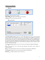
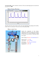
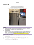
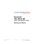
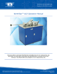
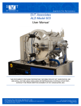
Cambridge NanoTech ALD System – User Instructions
This is a shortened version that focuses mainly on the
operation. For more detailed instructions, please refer to the
user manual “Cambridge NanoTech Savannah 100 Atomic
Layer Deposition System” available both on-line and near the
ALD setup.
System description
Atomic layer deposition (ALD) is a technique that allows growth of thin films with atomic layer
precision. The ALD system in PRISM clean room is designated for growth of Al2O3 film, which
uses water and trimethylaluminum (TMA) as precursors. ALD is a self-limiting process so each
cycle produces exactly a monolayer with a maximum of 1.1Å of Al2O3 depending on the
temperature.
Before starting: Important notes
•
TMA is pyrophoric and ignites when in contact with the air. Never remove TMA
source.
•
The chamber lid and the walls are HOT! Use care when opening the chamber. Do not
place any flammable materials on or near the ALD machine.
•
The chamber lid cannot be lifted if the chamber is cold. The temperature of the
chamber outer heater should be set to at least 80ºC.
•
Do not put in materials that will outgas. Do not use a substrate having carbon tape. Do
not use vacuum grease on your substrate or in the chamber.
•
System is intended to have the pump running, nitrogen flowing, and heaters on at all
times, even when idle.
•
If restarting the system after it has been cold, e.g. following a power outage or
maintenance shutdown, warm up the system first and follow the out-gassing procedure
completely as described in the system manual. If you are not sure, contact Helena, Joe or
one of the superusers to restart the system.
•
In case that either of the precursors is running out, indicated by the disappearance of
pulses during the running cycles, contact Helena, Joe or one of the superusers for
replacement. Do not attempt to change precursors by yourself.
•
The largest wafer size supported is 4” circular.
•
Always set the center heater to 150ºC and the outer heater to 150ºC after you finish
the growth.
1
Software user interface
Buttons:
Program ⎯ Stop the Labview program
Stop Valve ⎯ Open and close the stop valve to the pump
All heaters ⎯ Turns all the heaters ON/OFF
Run cycle area:
Cycle matrix ⎯ Programming of the cycle recipe. Valve indicates the source valve to be opened.
Valve 0 connects to the DI water precursor, and 1 to the TMA precursor. Pulse sets the time for
which the source valve is opened. Valves only respond to pulsing for t>0.007 sec. Expo gives the
time for which the stop valve is closed after pulsing the source and before pumping the chamber.
See exposure mode below. Pump sets the time between the pulses of each source, in which the
chamber is pumped and vapor removed. This should be long enough so that the chamber reaches
base pressure before next pulse.
Cycles ⎯ Programmed number of cycles. The current cycle number is displayed underneath.
Flow ⎯ Sets the flow rate of carrier gas (here nitrogen with ultra-low water content) as
controlled by MFC.
Delay ⎯ Time delay before the start of a run. Usually set for temperature stabilization.
Save Run ⎯ Check the box to save the run data in the file described below.
Run Time ⎯ Calculated total time for the current run.
2
Start/Abort Run ⎯ Start or abort the current run. The arrow turns bright green as run starts and
gray green as it stops.
Reactor Pressure Plot Area:
This plot tracks the reactor pressure read by the gauge installed in the pumping line assembly.
Pulses can be seen on the plot. Time scale can be reset by Reset Time.
Heaters control Area:
Control the temperature of the heaters.
Temperatures can be set by typing values into the
light blue areas. The current temperature readings
are indicated in the red area of each heater under
the set point.
Heater settings: Maximum / Recommended (°C)
Solenoid valve ⎯ 115 / 80
Center heater ⎯ 400 / 250-300
Outer heater ⎯ 200 / 150 (80 minimum)
Tee and elbow ⎯ 180 / 150
Pumping line ⎯ 180 / 150
3
Operating Instructions:
Load/Unload
1. Close the stop valve and set the flow rate to 100 sccm to vent the chamber. Only vent
when system hot (chamber >60°C). Leave system vented for as short a time as possible.
2. Wait for the lid to rise slightly from the chamber. Please be patient, it is important to
wait for the chamber to reach atmospheric pressure to preserve the integrity of the
O-ring.
3. Lift the lid and place your sample in the center of the chamber. Close the lid.
4. Open the stop valve to pump down the chamber. The base pressure should be less than 1
Torr, depending on the flow rate.
Growth run ⎯ Continuous flow mode (recommended)
1. Pump down the reactor chamber by opening the stop valve after loading sample.
2. Make sure all heaters are set to the desired temperatures.
3. Enter the desired values for cycle parameters. A typical recipe is below. This recipe
below will give you 300 monolayers (approx. 33 nm) of Al2O3.
Valve
0
1
Pulse (s)
0.07
0.07
Expo (s)
0
0
Pump (s)
4
4
Cycles
300
Flow (sccm) Delay (min)
20
0
4. Click Start run in the run cycle area. You can see the pulses in the pressure plot area.
5. After the run is over, vent the system and remove your sample. Close the lid and pump
down with flow rate set to 20 sccm. Let the system idle.
Growth run ⎯ Exposure mode
Exposure mode can be used for the ultra high aspect ratio structures. A typical recipe is listed
below. For both valves, Pulse sets to 0.2 sec; Expo sets to 4 sec to allow fully reaction of the
current precursor with the sample surface; Pump sets to 10 sec to provide sufficient time to
remove any un-reacted precursor and/or by products. Carrier gas is recommended and Flow can
use 5sccm.
Degassing (only after installation of precursors or system checked for leaks)
Water cylinder ⎯ Valve 0, Pulse = 1.3, Expo = 0, Pump = 3, Cycle = 5, Flow = 5
TMA cylinder ⎯ Valve 1, Pulse = 1.3, Expo = 0, Pump = 3, Cycle = 5, Flow = 5
Keep the manual valve of TMA source still closed while degassing. Degassing is essential
every time the space between manual and solenoid valves is open to air.
4