1
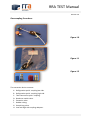
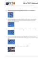
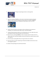
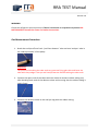
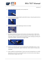
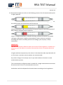
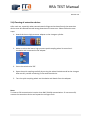
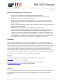
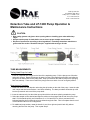
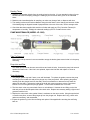
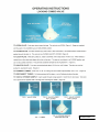
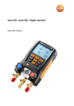
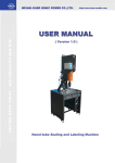
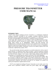
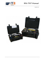
RRA TEST Manual Revision 2.6 RRA TEST Manual Revision 2.6 Objective Gas extraction and testing can be carried out to identify suspected contamination of R134a or R404a (HCFK) refrigerant with a false refrigerant containing R40 (Methyl Chloride). This test shows R40 and also has a certain sensitivity to all other organ chlorines, but not (in all cases) as disruptive or dangerous (need) to be. The main goal of this test is to protect the safety of all people involved or nearby refrigerant systems. The presence of R40 in a refrigerant system is an enormous safety risk. The risk of contact and or working on these contaminated systems is reduced to a minimum by using our test before handling, loading and or repairing these systems. When there is a positive result, which conclude that R40 may exist in the system, this system must be marked as “dangerous“ and handled with care accordingly local safety protocols. This method is designed to use a sample with a minimal amount of equipment, where the set-up, preparation & gas sample test are carried out at a distance from the reefer machine. An objective of this procedure is for all stages to be carried out to minimize health and safety risks. Warnings Before proceeding, first read through the whole manual to ensure the process is fully understood, always be sure to use the latest version of this manual. The latest version can found at www.rratest.com. R40 can react with aluminum components in the compressor to form a pyrophoric gas TMA (Trimethylaluminum). The process must be perfectly followed in chronological sequence. Each step must be carried out as described. NO step should be ignored or its position modified in the process. It is advised that only competent, fully trained and licensed personnel who are authorized to work with refrigerants should conduct this procedure. At least two persons should be present at the test. The second person does not have to be a licensed technician but should be available to give assistance to the person doing the test, if required. RRA TEST Manual Revision 2.6 No sampling method can be completely risk free. Operators should consider that the risk of not sampling and testing before working on a machine is likely to be greater. Important: As we are continuously working on the improvement of products, we reserve the rights to change the specifications without any prior notice. Pre-steps at the reefer unit. 1. The reefer unit must be positioned away from any electrical source, flames or open fire, heating source or static electricity. 2. The reefer unit must be un-plugged from electrical source. 3. No personnel are permitted inside the refrigerated container while samples are being taken. 4. Use Safety tape to set up a safe zone for testing and restrict access by unauthorized personnel. 5. Enforce a non smoking zone. In the safety zone any work involving heating or open flame should be forbidden. 6. Provide a class C (dry powder) & class D fire extinguisher. 7. Wear personal protective equipment for safety, such as goggles, gloves, high visibility vest & safety helmet. 8. Visually inspect the refrigeration system for any unusual damage and / or corrosion. Important: If at any time during the procedure smoke or something unusual is observed at the machine or sampling unit, the test must be terminated immediately. RRA TEST Manual Revision 2.6 Tools & equipment pre check Before setting up the extraction system, ensure all components are in full working order and fit for purpose. Check all seals and ensure all shut off valves are fully operational. Tools / Parts required 99,99 % purity by volume N2 (nitrogen) in bottle. Electrical or hand vacuum pump. Gas analysis bag. RRA Extraction Device, incl. adapters and couplings. Personal protective equipment safety goggles and gloves. Colorimetric detector tubes. RAE sample hand pump. Pre- Check Check the RAE sample hand pump for leak tightness, as described in the enclosed pump manual. RRA TEST Manual Revision 2.6 Gas sampling Procedure: Figure 1.0 Figure 1.1 Figure 1.2 The extraction device contents: A. B. C. D. E. F. G. H. Refrigeration quick- coupling low side. Refrigeration quick- coupling high side. Tube connection quick- coupling. Dead man switch valve. Extraction tube. Rubber tubing. Sample bag valve. Low and High side coupling adapters. RRA TEST Manual Revision 2.6 START 1. Make sure that the quick-coupling “A or B” is closed by turning completely anticlockwise the wheel. 2. Connect the extraction tube between “A or B” and “D” using the tube connection quick valves “C”. Make sure that the tube is pushed to the end of the valve “C” completely to avoid air leakiness. 3. Connect the extraction tube “E” to the dead man switch valve “D” and make sure that the tube is pushed to the end of valve “C”. 4. Connect a new tube “E” to the outlet of valve “D” and make sure that the tube is pushed to the end of valve “C” and install the rubber tube “F” to the other side of the tube. 5. Connect the rubber tube “F” over the gas sample valve “G”. RRA TEST Manual Revision 2.6 6. Open the valve “G” of the gas sample bag as shown on the bags label. 7. Attach the coupling “A or B” to a electrical or hand vacuum pump by using the adapters, open the quick coupling by turning clockwise the wheel “A or B and vacuum the extraction device completely by pressing the valve switch “D”. 8. Detach the vacuum device by closing the quick coupling (turn the wheel anticlockwise). The extraction device will remain in vacuum condition. 9. Connect the gas extraction device on the refrigeration unit, low or high side can be used (Advise: avoid connections where oil may come out). 10. Open the quick coupling carefully by slowly turning the wheel clockwise while the switch valve “D” is pressed to regulate the gas flow and fill the analysis bag up to 50% of its volume. 11. Close the quick coupling “A or B “ by turning the wheel anti-clockwise. 12. Close valve “G” on the gas sample bag and detach the RRA Extraction Device from the refrigerant system. 13. Detach the sample bag from the extraction device. RRA TEST Manual Revision 2.6 WARNING: Check the refrigerant system pressure. If there is a vacuum or no pressure is present DO NOT PROCEED! Contact the owner for further instructions. Gas Measurement Procedure: 1. Break the end tips off one fresh “pre-filter detector” tube and one ‘analyzer’ tube in the ‘tube tip breaker’ of the pump. Important: The process of breaking the tube ends can generate flying glass bits and leave the tube with sharp edges. Use eye and hand protection while breaking the tube ends. 2. Connect the open ends of the tubes with the chemical resistant rubber tubing only after breaking both ends of the detector tubes and ensuring that the rubber tubing is tightly fitted. 3. Connect the detector tubes to the analysis bag with the rubber tubing. RRA TEST Manual Revision 2.6 4. Insert the analyzer tube securely into the pump inlet. 5. Make certain that the pump handle is pushed all the way in. Align the guide marks on the pump body and handle. 6. Open the Valve on the gas sample bag as shown on the label. 7. Pull pump handle all the way out until it locks on. One pump stroke is 100ml. Wait about 15 seconds, during which time the discoloration of the analyzer tube must be continually monitored. Then confirm the completion of the sampling by checking the ‘end of flow’ indicator, located on the plunger handle. 8. If there is no colorization, give one more pump stroke as described in item “7” for a more accurate measurement, repeat 2 times more, so that a total of 4 strokes were completed. 9. Check carefully for any discoloration. If you are sure and convinced there is no visible discoloration, the risk of a contaminated system is minimal and the analysis bag can be flushed with nitrogen and re-used. RRA TEST Manual Revision 2.6 10. Discoloration apparent similar to the following pictures. Risk of contaminated system is highly apparent. Minor yellow discoloration: The chance of chlorine contamination is highly apparent, the concentration of contamination will be minimal. Yellow discoloration: High concentrations of chlorine and /or a low concentration of R40 / R142b (<150ppm) may be apparent. Yellow - orange discoloration: indicates the likely presence of R40 and / or R142B >150 ppm. Lab analysis is highly recommended. Further actions are required according lab results and safety protocols accordingly your company’s safety instructions. IMPORTANT: This test is an indicative field test where the chance of false negatives is reduced to a minimum level. We advise to conduct a lab test when there is any doubt about the results. In higher ambient temperatures, the colours in the detection tubes may fade after 10 or 15 minutes so written notes or photos are recommended. Any colour change in the analyze and / or pre-tube indicates that there is some contamination present. The risk assessment refrigerant tube is suitable for a single measurement and cannot be reused, even if there is no discoloration occurred. Used tubes need to be disposed as chemical waste according to local regulations. RRA TEST Manual Revision 2.6 2.4) Cleaning of extraction device: After each use, especially when contaminated refrigerant has been found, the extraction device must be cleaned to avoid wrong detection on future tests. Please follow the next steps: 1. Attach the low or high pressure adapter to the nitrogen cylinder. 2. Make sure that the low or high pressure quick coupling wheel is turned anticlockwise and connected to the adapter. 3. Press the switch valve “D”. 4. Open the quick coupling carefully by turning the wheel clockwise and let the nitrogen blow out any residue remaining in the extraction device. 5. Turn the quick coupling wheel anti-clockwise and detach from the adapter. Note: To clean a CFK contamination is easier than R40 / R142b contamination. If not successful, vacuum the extraction device and repeat the nitrogen flush. RRA TEST Manual Revision 2.6 Notifications regarding use and purpose. These tests are designed for risk assessment and safety purposes only. Analyzing the samples by an accredited laboratory will give confirmation of results. HRS & RAE cannot be held responsible for the results. HRS & RAE cannot in any way be held responsible for any consequences involving this test. Users must be aware of legislation that applies in the area (country) where the testing is being carried out. Follow closely those regulations regarding waste refrigerants and other chemicals which must be disposed of in a proper way. HRS & RAE are not responsible in any way for the disposal of any waste. It is entirely the responsibility of the user of the equipment (detector tube with pump) to see that the equipment is operated, maintained, and repaired in strict accordance with the manufacturer’s instructions provided with the equipment. It is also the responsibility of the user to ensure that the tubes are not used beyond their expiration date. The manufacturer and manufacturer’s distributors are not otherwise liable for any incorrect measurement and its consequences of any damages resulting from user’s negligence or otherwise. Disclaimer. RRA has carefully selected all the materials for our kit. The parts work in cooperation with each other. Original replacement parts must be ordered as RRA kit is a system which has a proven track record in determining risks involved in refrigerants and the contamination thereof. Serious issues to health and even possible death can result from using incorrect materials and not reverting to our user manual. RRA does not accept any responsibility for incorrect measurements made with aftermarket gasbags or other parts what so ever not supplied by RRA. Any quality issues implied by the use of aftermarket parts either good or bad can never lead to a liability to the RRA system. It is for this reason that our refill kits are always supplied with our gasbags. Contact: For technical support and / or questions, please contact “RAE-Benelux.” by mail: [email protected] or by phone: +31 10 44 26 149, For all other questions, please contact “Holland Reefer Service B.V.” by mail: [email protected] or by phone: +31 181 234 244 Caution: In case the glass tube would break and the chemical powder is spilled on hands or other body parts, please rinse off with lots of water, if the powder is swallowed, please contact a medical doctor immediately. RAE Systems Inc. 1339 Moffett Park Drive Sunnyvale, CA 94089 USA Tel: 1.408.752.0723 FAX: 1.408.752.0724 Detection Tube and LP-1200 Pump Operation & Maintenance Instructions CAUTION: • Wear safety glasses and gloves when opening tubes or handling open tubes with sharp edges. • Always test the pump for leaks before use to ensure proper sample measurement. • Dispose of spent tubes according to local regulations. Potentially hazardous materials are given under the section “Reaction Principle” supplied with each type of tube. TUBE MEASUREMENTS Testing Hand Pump for Leaks: Insert an unopened tube snugly into the inlet of the aspirating pump. Pull the plunger one full stroke and wait 2 minutes. Rotate the plunger dot away from the pump-shaft alignment mark, and allow the plunger to be drawn back into the pump shaft. Keep your hand on the shaft to keep it from springing back too suddenly. There are no leaks if the plunger returns to within 3 mm of its original position. Measurement Procedure: 1. Break both ends of a new detection tube using the tip breaker on the side of the pump. Insert the tube until it stops and then back off about 1 mm before breaking. The latter procedure allows the tip to fall into the tip reservoir at the end of the pump shaft. 2. Insert the tube securely into the rubber pump inlet with the tube arrow pointing towards the pump. 3. Select the sample volume desired and align the red dot on the plunger with the red line on the pump shaft. Pull the handle quickly until it latches at ½ or 1 full stroke (50 or 100 mL) and wait for the indicated sampling time to allow the air to be drawn through the tube. Flow is complete when the endof-flow indicator returns to its full brightness. 4. For additional pump strokes, rotate the handle ¼ turn left or right and push it back fully without removing the tube from the pump. Then repeat Step 3. Reading Tubes: 1. Read the concentration directly from the scale printed on the tube. If a non-standard number of pump strokes was used for sampling, multiply the reading by the correction factor given on the tube data sheet. 2. Read the tube immediately after air sampling, as colors may change, fade, or disperse with time. 3. The reading is taken as the furthest distance along the tube that the color change just becomes visible. If the leading edge is diagonal instead of perpendicular to the axis of the tube, use the average value. 4. Check the data sheet supplied with each box of tubes and apply any CFs (Correction Factors) for temperature or humidity. Multiply the observed reading by the CF to obtain the true value. PUMP MAINTENANCE (MODEL LP-1200) Tube Tip Reservoir Remove the tube tip reservoir cover as needed to empty the broken glass reservoir that is in the pump end fitting. Pump Inlet and Filter The rubber pump inlet can become worn with use and result in leaks. Unscrew the pump inlet nut and replace the rubber inlet. If the inlet is not replaced, inspect the inlet filter and replace or clean as necessary. Pump Mechanism 1. The plunger gasket may leak if worn or not well lubricated. To replace the gasket, unscrew the pump end fitting on the handle side and pull the plunger out of the pump shaft. After replacing the gasket, carefully push the plunger back into the shaft; use a fine screwdriver or tweezers to help ease the gasket into the shaft. Lubricate the inside of the shaft with vacuum grease to ensure a good seal. Caution: Do not over tighten the plunger gasket. It could cause a sudden loss of vacuum. 2. The inlet check valve may cause leaks if worn or not lubricated. Unscrew the end fitting on the inlet side and pull out the disk-shaped rubber-inlet check valve. Replace as necessary adding a light coat of grease around the hole. 3. Replace the outlet check valve gasket if there is resistance on the return stroke. Using the special tool or needle-nose pliers, unscrew the plunger tip from the plunger rod. Replace the O-ring, check valve gasket as necessary, and reassemble. 4. Inspect the gasket ring in the inlet end fitting and replace if damaged before screwing the end fitting back on. File: N/Tubes/Pumps/LP-1200 Vers. 4/29/03 RRA Gas Sample Bag Part # RRA-5030