1
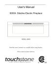
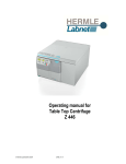
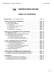
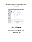
650.66-O2V (998) 035-15813-301 USER’S INFORMATION MANUAL USE AND CARE INSTRUCTIONS FOR ALL POSITION AUTOMATIC IGNITION FURNACES If the information in this manual is not followed exactly, a fire or explosion may result causing property damage, personal injury or loss of life. Do not store or use gasoline or other flammable vapors and liquids in the vicinity of this or any other appliance. WHAT TO DO IF YOU SMELL GAS • Do not try to light any appliance. • Do not touch any electrical switch; do not use any phone in your building. • Immediately call your gas supplier from a neighbor's phone. Follow the gas supplier's instructions. • If you cannot reach your gas supplier, call the fire department. Installation and service must be performed by a qualified installer, service agency or the gas supplier If not installed, operated, and maintained in accordance with the manufacturer's instructions, this product could expose you to substances in fuel or from fuel combustion which are known to the State of California to cause cancer, birth defects or other reproductive harm. Also, operation, installation and servicing of this product could expose you to airborne particles of glasswool fibers known to the State of California to cause cancer through inhalation. Introduction Your furnace will give you all the comforts of complete winter air conditioning - heating, circulation, filtering - you have control and yet the furnace is as automatic as you desire it to be. If you will observe the few operating and maintenance instructions in this booklet, this high efficiency forced warm air furnace will give you many years of dependable service. Failure to observe the following safety precautions could cause fire, explosion, or asphyxiation. Safety Precautions For your safety – Do not store or use flammable liquids, vapors, or materials in the immediate area near the furnace or other heating appliance. Do not store brooms, mops, or equipment or materials near the furnace in any confined space which may be around or in front of the furnace. When the furnace is installed in an attic or other insulated space, make sure that all insulation is at least 12” away from furnace combustion air openings. Failure to do this could cause asphyxiation or fire. 2 Adequate ventilation and combustion air must be provided to insure satisfactory and safe operation of the furnace. Air openings in front panel and top panel must not be obstructed. Any openings into the furnace closet or confined room in which the furnace is located, for the entrance of combustion and ventilation air must be kept open and unobstructed. Failure to observe these requirements could result in asphyxiation. NOTICE – Do not use this furnace if any part has been under water. Immediately call a qualified service technician to inspect the furnace and to replace any part of the control system and any gas control which has been under water. Should overheating occur, or the gas supply fail to shut off, shut off the manual gas valve to the appliance before shutting off the electrical supply. Do not store or use halogen-emitting substances in the vicinity of this appliance. Such substances include chlorine based cleaners and swimming pool chemicals, water softening chemicals, de-icing salts and chemicals, cleaning solvents such as carbon tetrachloride or perchloroethylene, halogen type refrigerants, printing inks, paint and paint removers, varnishes, hydrochloric acid, cements and glues, and masonry acid washing materials. The air used by the burner for combustion must be free of halogens to avoid possible corrosion to the heating surfaces, which could result in asphyxiation. Improper installations, adjustment, alteration, service or maintenance can cause property damage, personal injury or loss of life. Installation and service must be performed by a qualified installer, service agency or the gas supplier. Never attempt to modify this furnace. Fire, explosion, or asphyxiation may result. If malfunction occurs, obtain the assistance of a qualified service agent. FIGURE 1 – DOWNFLOW POSITION FIGURE 2 – UPFLOW POSITION 3 Description This furnace can be installed in the upflow, downflow, or horizontal position. Figure 1 shows a typical model in the downflow position and figure 2 shows a typical model in the upflow position. The furnace may also lie on either side in a horizontal position. The furnace is equipped with an induced-draft vent blower and atmospheric burners. Combustion air is taken from the space or area in which the furnace is installed and drawn into the burners through the louvers in the front panel. Flue gas is drawn from the furnace by the vent blower and discharged through the flue pipe to the outside atmosphere. This is a forced air furnace. The furnace circulating air blower draws cool air from the house, passes it over the hot furnace heat exchanger and circulates the warmed air through the ductwork to the house. The furnace is equipped with the controls necessary for proper operation. The various components referred to in this manual and on the furnace nameplate are identified in Figures 1 and 2. Sequence of Operation These furnaces are equipped with an electric hot surface burner ignition system. In response to a call for heat by the room thermostat, the burners are lighted by a hot glowing ignitor at the beginning of each operation cycle. The burners will continue to operate until the thermostat is satisfied at which time all burner flame is extinguished. During the off cycle no gas is consumed. With the room thermostat set below room temperature, and with the electrical power and gas supply to the furnace on, the normal sequence of operation is as follows: 1. When the room temperature falls below the setting of the room thermostat, the thermostat energizes the furnace control board. 4 2. When the furnace control board is activated, the vent blower is turned on. A circuit is also made through the normally open pressure switch contacts. 3. As the vent blower increases in speed, the contacts of the pressure switch will close and complete the electrical circuit to the ignitor. 4. During the next 15-30 seconds, the vent blower will bring fresh air into the heat exchanger and the ignitor will begin to glow. At the end of this period, the gas valve will open and the burners will light. 5. After the burners light, a separate sensor acts as a flame probe to check for the presence of flame. As long as flame is present, the system will monitor it and hold the gas valve open. 6. If the burners fail to light within 6-8 seconds after the gas valve opens, the gas valve will close and the ignitor will be turned off. After a short pause, the system will recycle and try again for ignition. If the burners fail to light after three tries, the ignition system will lock out. The system will remain in lockout mode until one hour has passed, or until the room thermostat is cycled off then back on. The furnace will then try for ignition again. 7. The lapsed time from the moment the room thermostat closes to when the burner light may be 30-40 seconds. This delay is caused by (1) the time required for the vent blower to come to full speed, (2) the time required for the ignitor to heat up and (3) the time required for fresh air to be brought into the heat exchanger. 8. Thirty to forty seconds after the burners have lighted, the fan switch will close and the furnace air circulation blower will run. 9. When room thermostat is satisfied, the circuit to the furnace control board is broken. The circuit to the gas valve is broken and the burners are extinguished. The vent blower will continue to run for a few seconds. The furnace control board will keep the circulating blower running for a fixed period of time to allow additional heat to be drawn from the heat exchanger. Furnace Operation Safety Information For your safety read before operating: If you do not follow these instructions exactly, a fire or explosion may result causing property damage, personal injury or loss of life. 1. This appliance does not have a pilot. It is equipped with an ignition device which automatically lights the burners. DO NOT try to light the burners by hand. 2. Before operating, smell all around the appliance area for gas. Be sure to smell next to the floor because some gas is heavier than air and will settle on the floor. What to do if you smell gas: • Do not try to light any appliance. • Do not touch any electrical switch; do not use any phone in your building • Immediately call your gas supplier from a neighbor’s phone. Follow the gas supplier’s instructions. • If you cannot reach your gas supplier, call the fire department. 3. Use only your hand to turn the gas control lever or switch. Never use tools. If the lever or switch will not move by hand, don’t try to repair it, call a qualified service technician. Force or attempted repair may result in a fire or explosion. 4. Do not use this appliance if any part has been under water. Immediately call a qualified service technician to inspect the appliance and to replace any part of the control system and any gas control, which has been under water. Operating Instructions 1. STOP! Read the safety information listed above. 2. Set the thermostat to the lowest setting, or OFF. 3. Turn off all electric power to the furnace. 4. This appliance does not have a pilot. It is equipped with an ignition device which automatically lights the burners. Do not try to light the burners by hand. 5. Remove front door panel. 6. Move gas valve control lever or switch to "OFF". See Figure 3. Gas Shutoff This furnace is equipped with a gas shutoff lever or switch on the gas valve, which can be used to prevent gas from flowing to the furnace. Figure 3 shows the location of the shutoff lever or switch. To turn off gas to the furnace, move the lever or switch to the "OFF" position. The furnace installation should also have a manual shutoff valve in the gas piping to the furnace, similar to what is shown in Figure 4. To turn off the gas to the furnace, use a wrench and turn the knob or lever so that it is pointing 90 degrees from the gas pipe, as shown in Figure 4. FIGURE 4 – MANUAL SHUTOFF VALVE GAS Thermostat Set the room thermostat at the desired room temperature. Greatest comfort will be achieved when the setting is not changed frequently. For energy conservation and economy - It is recommended that the thermostat be set at 68° for heating and 80° for cooling. FIRGURE 3 – WHITE-RODGERS GAS VALVE 7. Wait five (5) minutes to clear out any gas. Then smell for gas, including near the floor. If you smell gas, STOP! Follow #2 in the Safety Information. If you don't smell gas, go to the next step. 8. Move gas control lever or switch to "ON". 9. Replace front door panel. 10. Turn on all electric power to the furnace. 11. Set thermostat to desired setting. For Heating with Air Conditioning Applications - Set HEAT/COOL switch to HEAT position and set FAN switch to AUTO position. Energy Saver Thermostat - An energy saver thermostat or setback thermostat will provide even greater fuel economy. This type of thermostat may be set to control the temperature at a "HIGH" setting during the daytime hours and a "LOW" setting during night-time hours. Follow the instructions supplied with the thermostat by the thermostat manufacturer. If these are not available, check with the installing dealer or contractor for proper setting and operation of your specific thermostat. If Furnace Fails to Operate Properly: 1. Check setting of thermostat, and position of HEAT/COOL switch if air conditioning is installed. If a setback type thermostat is employed, be sure that the thermostat is in the correct operating mode. 2. Check to see that electrical power is ON. 3. Check to see that the lever or switch on the gas control valve is in the full ON position. 4. Make sure filters are clean, return grilles are not obstructed, and supply registers are open. 5. Be sure that furnace flue piping is open and unobstructed. 6. This furnace is equipped with a BLOWER DOOR SAFETY SWITCH. It is located behind the blower door. See Figures 1 or 2 . The switch controls the electrical power to the furnace and prevents the furnace from operating if the blower door is not in place or is improperly installed. 7. This furnace is equipped with three rollout switches, which are designed to shut down the furnace in the event that excessive rollout occurs. These switches are located near the burners as shown in Figures 1 or 2. If any of these switches shuts down the furnace, do not attempt to restart it. Call a service technician to correct the problem 5 If the cause for the failure to operate is not obvious, do not attempt to service the furnace yourself. Call a qualified service agency or your gas supplier. Filters It is very important that filters in your furnace or air conditioning system be cleaned frequently or replaced when necessary. Clean filters not only provide added comfort and a more healthful environment, but also allow the system to operate more efficiently. Check filters every two or three weeks. Your furnace may be equipped with a permanent type filter, which need not be replaced provided it is cleaned frequently. A permanent filter may be washed in a mild solution of detergent and water and then rinsed thoroughly with clear water. If the pores of the filter media become clogged with dirt or lint, FIGURE 5 – DOWNFLOW FILTERS 6 which cannot be washed out, or if the filter becomes damaged, it must be replaced. A replacement filter should be of the same type and the same size as the old filter. Filter Replacement Downflow – In your installation the filter may be located in the return air duct above the furnace as shown in Figure 5, or it may be located behind a return air grille. If the filter is located in the return air duct above the furnace, replace the filters as shown in Figure 5, with the bottom of the filter resting in the filter rack and the top edges of the filters leaning against the inside of the duct. If the filter is not located in the return air duct above the furnace or if the method of removal and replacement is not obvious, then contact the installing contractor of the furnace for assistance. FIGURE 6 – UPFLOW FILTERS Filter Replacement Horizontal – The filter may be located in a filter rack near the furnace, or it may be located behind a return air grille. If you cannot find the filter, or if the method of removal and replacement is not obvious, then contact the installing contractor of the furnace for assistance. Filter Upflow Replacement – The filter may be located in a filter rack attached to the side of the furnace or it may be located in a filter rack beneath the furnace. See Figure 6. If the filter is not located in one of these places, or if the method of removal and replacement is not obvious, then contact the installing contractor of the furnace for assistance. Periodic Inspection and Maintenance It is recommended that the homeowner or user make an inspection of the furnace at least every 90 days or more often if desired. It is also recommended that a qualified service agency inspect the furnace before each operating season the furnace is used, both heating and air conditioning, and at any time that there is an indication of malfunction. The owner/user should not attempt to disassemble the furnace unless experienced and qualified to do so. FOR SAFETY – Turn off electrical power to furnace before performing any service. The furnace installation should be examined to determine that: 1. All flue product carrying areas external to the furnace (chimney, vent connector, etc.) are clear and free of obstructions, 2. The vent connector is in place, slopes upward, and is physically sound without holes or excessive corrosion, 3. The return air connection is physically sound, is sealed to the furnace casing, and terminates outside the space containing the furnace, 4. The physical support of the furnace is sound without sagging and the furnace is level, and 5. There are no obvious signs of deterioration of the furnace. nation of the flue outside the structure and look for any indication of carbon or soot streaks. The presence of any soot would indicate a malfunction and the cause must be determined and corrected. Motor Lubrication The circulating air blower motor and vent blower are permanently lubricated and do not require periodic lubrication. When You Call For Service Assistance Very often time can be saved if you will give the service company the MODEL and SERIAL NUMBER of your furnace. This will enable the company to determine the specific components used, and perhaps to better identify the possible problem and be better prepared if a service call is required. To Contact Your Service Technician This equipment must be serviced only by qualified individuals specially trained and experienced in servicing of this type equipment and related system components, such as duct systems, air conditioning, etc. Installation and service personnel are required to be licensed in some areas. Persons not qualified should not attempt to service this equipment. Your Service Technician Your furnace's best friend is your qualified service technician. If the unit gives any indication of improper operation, call your service technician. If the service technician is allowed to perform the normal routine care of your furnace, he/she can many times detect potential difficulties and make corrections before trouble develops. Preventative maintenance of this type will allow you to operate the unit with a minimum of concern, and at the same time will pay for itself in added years of comfort. For immediate reference, fill in the following blanks and keep this booklet in a safe and easily accessible place. COMPANY: ____________ ADDRESS: ____________ TELEPHONE: ____________ Trips and Vacations The furnace is equipped with controls which are designed to shut off the furnace burners should malfunction occur. However, it is best never to assume that the furnace will operate unattended for long periods of time, especially if there is a possibility of damage to your property because of freezing. If you plan to be away for an extended period, it is suggested that arrangements be made for someone to check the house and furnace operation frequently. Flue Piping Inspect the flue piping connection at the furnace and the connection of the individual sections to ensure that pipe joints have not become disengaged and that there are no openings, which could allow leakage of products of combustion. Inspect the termi7 Subject to change without notice. Printed in U.S.A. Copyright by Unitary Product Group 1998. All rights reserved Unitary 5005 Norman Products York OK Group Drive 73069 035-15813-301 (998)