1
User’s Information Manual
Condensing Gas Furnaces
Fan Assisted Combustion System
Upflow / Horizontal and Downflow / Horizontal
WARNING: If the information in this manual
is not followed exactly, a fire or explosion may
result causing property damage, personal injury or loss of life.
—
—
Do not store or use gasoline or other
flammable vapors and liquids in the
vicinity of this or any other appliance.
WHAT TO DO IF YOU SMELL GAS
•
•
•
•
—
Do not try to light any appliance.
Do not touch any electrical switch;
do not use any phone in your building.
Immediately call your gas supplier
from a neighbor’s phone. Follow the
gas supplier’s instructions.
If you cannot reach your gas supplier, call the fire department.
Installation and service must be performed by a qualified installer, service
agency or the gas supplier.
GENERAL INFORMATION
WARNING: Improper installation, adjustment, alteration, service or maintenance can cause injury
or property damage. Refer to the installation instructions provided with the furnace and this
manual. For assistance or additional information
consult a qualified installer, service agency or the
gas supplier.
This information is intended for use by individuals possessing adequate backgrounds of electrical and mechanical experience. Any attempt to repair a central air
conditioning product may result in personal injury and/
or property damage. American Standard Inc. or seller
cannot be responsible for the interpretation of this
information, nor can it assume any liability in connection
with its use.
Understand the signal words DANGER, WARNING,
AND CAUTION. These words are safety alert words.
DANGER indicates the most serious hazards which will
result in severe personal injury or death. WARNING
© American Standard Inc. 1999
indicates hazards which could result in personal injury
or death. CAUTION is used to indicate unsafe practices
which could result in minor injury or property damage.
There must be a free flow of fresh air sufficient for
efficient combustion and safe ventilation of your furnace.
Do not allow the louvers on the front panels of your
furnace to become blocked as this will restrict the flow of
fresh air.
The combustion air for your furnace must be fresh
uncontaminated air. Paints, varnishes, laundry bleaches,
detergents, many household cleaners, water softening
salts, adhesives, and all such products release fumes
containing compounds which could lead to early heat
exchanger and vent system deterioration. Do not store
these type of products near your furnace and consider
fresh air for your furnace during construction or remodeling.
Never store gasoline, combustible materials, or
other flammable liquids or vapors near your furnace.
If you have a problem, check the "Problem Solver" section
of this manual before you call for a possibly unneeded
service call.
Parts and controls of this furnace are unique. Should
service or modification be required, be sure your servicer
uses only factory authorized parts, kits, or accessories
for this furnace.
CAUTION: Label all wires prior to disconnection
when servicing controls. Wiring errors
can cause improper and dangerous operation.
▲
WARNING: BODILY INJURY CAN RESULT FROM
HIGH VOLTAGE ELECTRICAL COMPONENTS, FAST MOVING FANS,
AND COMBUSTIBLE GAS. FOR PROTECTION FROM THESE
INHERENT HAZARDS DURING INSTALLATION AND SERVICING,
THE ELECTRICAL SUPPLY MUST BE DISCONNECTED AND THE
MAIN GAS VALVE MUST BE TURNED OFF. IF OPERATING CHECKS
MUST BE PERFORMED WITH THE UNIT OPERATING, IT IS THE
TECHNICIANS RESPONSIBILTY TO RECOGNIZE THESE HAZARDS
AND PROCEED SAFELY.
▲WARNING: DO NOT USE THIS UNIT IF
ANY PART HAS BEEN UNDER WATER. IMMEDIATELY
CALL A QUALIFIED SERVICE TECHNICIAN TO
INSPECT THE FURNACE AND TO REPLACE ANY
PART OF THE CONTROL SYSTEM AND ANY GAS
CONTROL WHICH HAS BEEN UNDER WATER.
Pub. No. 32-5022-07
Filter maintenance reduces energy use.
A clean filter saves money.
When the furnace circulates and filters the air in your home,
dust and dirt particles build up on the filter. Excessive accumulation can block the airflow, forcing the unit to work harder to
maintain desired temperatures.
And the harder your unit has to work, the more energy it uses.
So you pay more any time your system is running with a dirty
filter.
CAUTION: Never operate your unit for either heating or
cooling with filters removed.
Help ensure top efficiency by cleaning the filter once a month.
Clean it twice a month during seasons when the unit runs more
often.
You can clean the filter with a vacuum, OR you can wash it with
a household detergent.
Both methods are quick and easy, and guaranteed to improve
the performance of your system.
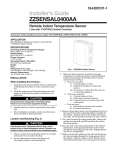
UPFLOW BOTTOM RETURN
For vertical UPFLOW ONLY, a left or right return air inlet as
above (left side shown) requires trimming of the factory supplied filter to 17" x 25" x 1" for both the 21" and 24-1/2" wide
furnaces.
Your filter may or may not be framed.
Replacing your filter.
When replacing your furnace filters, always use high velocity
type which are the same size as originally supplied. Filters are
available from your dealer.
Where disposable filters are used, they must be a high velocity
type which are the same size as originally supplied.
UPFLOW SIDE RETURN
Air filters may also be located outside of the furnace using a
SIDE FILTER FRAME.
How to remove your filter.
WARNING: Disconnect power to unit before removing
blower door.
Upflow furnaces use a high velocity type air filter which may be
located within the furnace blower compartment in either a
BOTTOM or SIDE (left or right) return air inlet. The furnace
may be secured with filter retaining brackets (as shown) or a
filter retainer wire.
To replace filters, remove blower access door, push back to flex
the filter and clear the filter retaining bracket at the front of the
unit. After cleaning, replace the filter in the same manner
making sure that the filter wire is secured in place in both front
and back filter retaining brackets. Replace blower access door.
A bottom return air inlet as shown features a 17" x 25" x 1" filter
in the 17-1/2" wide furnace cabinets; a 20" x 25" x 1" filter in the
21" wide models; and a 24" x 25" x 1" filter in the 24-1/2" wide
cabinet.
Page 2
UPFLOW ONLY
Pub. No. 32-5022-07
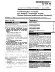
Upflow / Horizontal Furnace Filters
The Upflow/Horizontal furnace when installed horizontally
requires a horizontal filter kit. The filters may be located
remote to the furnace or in the return air duct near the furnace.
Check with your dealer for the location of your filters.
An upflow/horizontal furnace in horizontal return air filter
application, as shown, features two 16" x 20" x 1" filters in the 171/2", 21" and 24-1/2" wide furnace cabinets.
Downflow/Horizontal furnaces are factory supplied with 2 standard size permanent type air filters which may be located
remote to the furnace or in the return air duct. Check with your
dealer for the location of your filters.
A downflow/horizontal furnace return air filter application, as
shown, features two 14" x 20" x 1" filter in the 17-1/2" wide
furnace cabinets; or two 16" x 20" x 1" filter in the 21" and 24-1/
2" wide furnace cabinets.
DOWNFLOW FILTER
UPFLOW/HORIZONTAL WITH FILTER KIT
To replace filters, remove the filter access door, lift the filter
from the lower bracket and shift the filter to the side to free the
top filter from the bracket and slide the filters out through the
filter access door. After cleaning, replace the filters in the same
manner making sure that the filters are secured in place in both
top and bottom filter brackets. Replace filter access door.
A downflow/horizontal furnace return air filter application, as
shown, features two 14" x 20" x 1" filter in the 17-1/2" wide
furnace cabinets; or two 16" x 20" x 1" filter in the 21" and 24-1/
2" wide furnace cabinets.
Air filters may also be located outside of the furnace using a
remote filter grille. The filter grille could be in a hallway, wall,
or in the ceiling. Check with your dealer for the exact location
of your filter and the method of changing the filters.
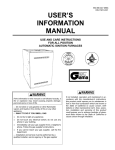
UPFLOW (Vertical) FILTER TABLES
REQUIRED FILTERS - BOTTOM
CABINET WIDTH
FILTER QUANTITY & SIZE
17-1/2"
1 - 17" X 25" X 1"
21"
1 - 20" X 25" X 1"
24-1/2"
1 - 24" X 25" X 1"
DOWNFLOW/HORIZONTAL FILTER
DOWNFLOW (Vertical) FILTER TABLE
REQUIRED FILTERS - SIDE **
REQUIRED FILTERS - DOWNFLOW
CABINET WIDTH
FILTER QUANTITY & SIZE
CABINET WIDTH
FILTER QUANTITY & SIZE
17-1/2"
1 - 17" X 25" X 1"
17-1/2"
2 - 16" X 20" X 1"
21"
1 - 20" X 25" X 1"
21"
2 - 16" X 20" X 1"
24-1/2"
1 - 24" X 25" X 1"
24-1/2"
2 - 16" X 20" X 1"
** ALL 5 TON AIRFLOW MODELS ("960"OR "V5"),
REQUIRE BOTH SIDES OR 1 SIDE AND THE BOTTOM,
OR JUST THE BOTTOM FOR SUFFICIENT AIRFLOW
Pub. No. 32-5022-07
Page 3
The problem solver.
A furnace is not a household appliance. It is complex and
requires professional maintenance and repair.
of your furnace should be made by a qualified service agency at
the start of each heating season.
That’s why attempts at “do-it-yourself” repairs on an in-warranty unit may void the remainder of your warranty.
Keep your furnace looking like new for years.
Other than performing the simple maintenance recommended
in this manual, you should not attempt to make any adjustments to your furnace. Your dealer will be able to take care of
any questions or problems you may have. A periodic inspection
Clean the enamel finish of your furnace with ordinary soap and
water. For stubborn grease spots, use a household detergent.
Lacquer thinner or other synthetic solvents may damage the
finish.
Save time and money. Before calling for service, check the following:
Problem
No Heating - Blower
Does not operate
1.
Possible Trouble
Thermostat set incorrectly.
1.
2.
Blown fuse or tripped circuit breaker.
2.
3.
Defective component.
3.
4.
5.
6.
Burner does not ignite.
Main gas line turned off.
Blower door removed or ajar.
4.
5.
6.
7.
Lockout
7.
Possible Remedy
Adjust thermostat See operating
instructions
Replace or reset protective device
or call for servicer.
Most controls are automatic and will
recycle. If your unit still does not
operate call for servicer.
Call servicer.
Have gas company check.
Close door securely to restore power
to blower and gas valve.
Turn power on-off-on-off twice
in 30 secs.
Insufficient Heating Blower operates
continuously
1.
Dirty air filters.
1.
Clean or replace filters.
2.
Blocked supply or
return registers.
2.
Make sure registers are open and
No obstacles blocking off the air.
No Heat - Vent motor
is running
Restricted or plugged furnace
condensate drain.
1. Remove drain clamps to condensate
trap and drain pan outlet
2. Flush or clear drain blockage.
3. Reinstall clamps.
Unusual Noise
Call your servicer
The following warning complies with State of California law, Proposition 65.
WARNING:
This product contains fiberglass wool insulation! Fiberglass dust and ceramic fibers are believed by the state of California to cause cancer through inhalation. Glasswool fibers may also cause respiratory, skin,
or eye irritation.
PRECAUTIONARY MEASURES
FIRST AID MEASURES
• Avoid breathing fiberglass dust.
Eye Contact
- Flush eyes with water to remove dust. If
symptoms persist, seek medical attention.
Skin Contact
- Wash affected areas gently with soap
and warm water after handling.
• Use a NIOSH approved dust/mist respirator.
• Avoid contact with the skin or eyes. Wear long-sleeved,
loose fitting clothing, gloves, and eye protection.
• Wash clothes separately from other clothing; rinse washer
thoroughly.
• Operations such as sawing, blowing, tear-out, and spraying may generate fiber concentrations requiring additional
respiratory protection. Use the appropriate NIOSH approved respirator in these situations.
Page 4
Pub. No. 32-5022-07
Maintenance information.
Never stop the cooling system by shutting off the main
power.
If the main power to your air conditioner is ever disconnected
for more than three hours, turn off the thermostat. Then wait for
at least three more hours after the power has been restored
before turning the thermostat back on. Failure to follow this
procedure could result in damage to your air conditioning
system.
1. GENERAL INSPECTION - Examine the furnace installation
for the following items:
a. All flue product carrying areas external to the furnace (i.e.
chimney, vent connector) are clear and free of obstruction.
b. The vent connector is in place, slopes upward and is
physically sound without holes or excessive corrosion.
c. The return air duct connection(s) is physically sound, is
sealed to the furnace and terminates outside the space
containing the furnace.
d. The physical support of the furnace should be sound
without sagging, cracks, gaps, etc., around the base so as to
provide a seal between the support and the base.
e. There are no obvious signs of deterioration of the furnace.
NOTE: On LP (propane) units, due to variations in BTU content
and altitude, servicing may be required at shorter intervals.
5. HEAT EXCHANGER / FLUE PIPE - These items must be
inspected for signs of corrosion, and/or deterioration at the
beginning of each heating season by a qualified service technician and cleaned annually for best operation.
6. CIRCUIT PROTECTION - If blower or gas valve fail to
operate, the cause could be the circuit breaker or a loose or
blown fuse. Replace fuse or reset circuit breaker.
2. BLOWERS - The blower size and speed determine the air
volume delivered by the furnace. The blower motor bearings are
factory lubricated and under normal operating conditions usually do not require servicing. Annual cleaning of the blower
wheel and housing is recommended for maximum air output,
and this must be performed only by a qualified servicer or
service agency.
3. IGNITER - This unit has a special hot surface direct ignition
device that automatically lights the burners. Please note that it
is very fragile and should be handled with care.
CAUTION: Do not touch igniter. It is extremely hot.
4. BURNER - Gas burners do not normally require scheduled
servicing, however, accumulation of foreign material may cause
a yellowing flame or delayed ignition. Either condition indicates that a service call is required. For best operation, burners
must be cleaned annually using brushes and vacuum cleaner.
7. OPERATION - Your warm air furnace should not be operated
in a corrosive atmosphere. Paint solvents, cleaning chemicals,
spray propellants, and bleaches should not be used in the
vicinity of the furnace during normal operation.
8. COOLING COIL CONDENSATE DRAIN - If you have a
cooling coil installed with your furnace, condensate drains
should be checked and cleaned periodically to assure that
condensate can drain freely from coil to drain. If condensate
cannot drain freely water damage could occur.
9. AIR CIRCULATION - To ensure increased comfort, blower on
this unit may be operated continuously for both heating and
cooling. This will result in constantly filtered air and aid in
maintaining more even temperatures by avoiding temperature
stratification throughout the conditioned area. To accomplish
constant air circulation, set your thermostat fan switch to "ON".
Turn off gas and electric power supply. To clean burners,
remove top burner bracket and lift burner from orifice. NOTE:
Be careful not to break igniter when removing burners.
Clean burners with brush and/or vacuum cleaner. Reassemble
parts by reversal of the above procedure.
NOTE: On LP (propane) units, some light yellow tipping of the
outer mantle is normal. Inner mantle should be bright blue.
Natural gas units should not have any yellow tipped flames. This
condition indicates that a service call is required. For best
operation, burners must be cleaned annually using brushes and
vacuum cleaner.
Pub. No. 32-5022-07
Page 5
WARNING:
Unit is equipped with a blower door switch which cuts power to
blower and gas valve causing shutdown when door is removed.
Unit must not be altered to allow operation with the blower door
removed. Operation with doors removed or ajar can permit the
escape of dangerous fumes. All panels must be securely closed
at all times for safe operation of the furnace.
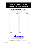
MANUAL MAIN
SHUTOFF VALVE
WARNING:
Should overheating occur, or the gas supply fail to shut off, shut
off the manual gas valve to the furnace before shutting off the
electrical supply.
In the event that electrical, fuel or mechanical failures occur,
the owner should immediately turn off the gas supply at the
manual gas valve located in the burner compartment and electrical power to the furnace and contact servicer.
For your safety.
Furnace area must be kept clear and free of combustible materials, gasoline, and other flammable vapors and liquids.
Air for combustion and ventilation.
GROUND
UNION JOINT
DRIP LEG
AUTOMATIC GAS VALVE
WITH MANUAL SHUTOFF
Manual Main Gas Shut-off Valve May Be
Located on the Left or Right Side
The flow of combustion and ventilating air must not be obstructed from reaching the furnace. Air openings provided in
the casing of furnace must be kept free of obstructions which
would restrict airflow, thereby affecting efficiency and safe
operation of your furnace.
MANUAL MAIN
SHUTOFF VALVE
Also, air openings provided to the area in which the furnace is
installed and the space around the furnace shall not be blocked
or obstructed. Keep this in mind should you choose to remodel
the area which contains your furnace. Furnaces must have air
for proper performance.
GROUND
UNION JOINT
If additional insulation is added after the furnace is installed,
the area around the furnace must be inspected to ensure it is
free and clear of insulation. If this furnace is installed in an attic
or other insulated space it must be kept free and clear of all
insulating materials as some insulating materials are combustible.
DRIP LEG
AUTOMATIC GAS VALVE
WITH MANUAL SHUTOFF
MANUAL MAIN
SHUTOFF VALVE
GROUND
UNION JOINT
DRIP
LEG
MANUAL MAIN
SHUTOFF VALVE
GROUND
UNION JOINT
DRIP LEG
AUTOMATIC GAS
VALVE WITH MANUAL
SHUTOFF
AUTOMATIC GAS VALVE
WITH MANUAL SHUTOFF
Manual Main Gas Shut-off Valve May Be Located on the Top or Bottom Side
Page 6
Pub. No. 32-5022-07
MAIN
MANUAL
SHUTOFF
VALVE
TOP VIEW OF LEFT SIDE PIPING
GROUND
UNION
JOINT
DRIP
LEG
AUTOMATIC GAS VALVE
WITH SHUTOFF
AUTOMATIC GAS VALVE WITH SHUTOFF
DOWNFLOW FURNACE Manual Main Gas Shut-off Valve May Be Located on the Right or Left Side
NOTE THE LOCATION OF THE MANUAL MAIN GAS SHUTOFF VALVE FOR YOUR FURNACE.
Have your installer or servicer show you the location if you have any questions.
To light furnace.
Lighting instructions.
will open and burners will ignite.
Your furnace is equipped with a hot surface direct ignition
device.
8. When thermostat is satisfied, main burners will extinguish.
WARNING.
Do not attempt to manually light the furnace.
9. If main burners fail to ignite, lower thermostat setting or
disconnect electrical supply, wait 5 minutes, raise thermostat
setting above indicated temperature.
1. Please read all safety information in this book before operating furnace.
10. If furnace will not light, turn “OFF” all gas and electricity to
unit and call servicer or gas supplier.
2. Set thermostat to lowest setting. Turn off all electric power to
furnace.
For complete shutdown.
3. Remove control access panel.
Turn gas cock knob on main gas valve to “OFF” position. Disconnect electrical supply to unit.
4. Turn gas cock knob on main gas valve with unit clockwise to
“OFF” position. If external gas cock is used, turn to “OFF”
position. Allow 5 minutes for any gas within the unit to escape.
LP gas being heavier than air may require forced ventilation. If
you smell gas STOP! Follow the “What To Do If You Smell Gas”
instructions on the front cover of this book. If you don’t smell gas,
go to next step.
CAUTION: If this is done during the cold weather months,
provisions must be taken to prevent freeze-up of all water pipes
and water receptacles.
5. Turn gas cock knob counterclockwise to “ON” marker.
Flame Roll-out Device.
6. Replace control access panel.
All models are equipped with a fusible link located near the
burners. In case of flame roll-out, the link will open (melt) and
cause the circuit to open which shuts off all flow of gas.
7. Turn on main electrical supply and set thermostat to desired
setting. Combustion blower will start and ignition device will
start to heat up. After approximately 15 seconds main gas valve
Whenever your house is to be vacant, arrange to have someone
inspect your house for proper temperature. If your furnace
should fail to operate, damage could result, such as frozen water
pipes.
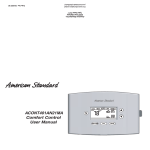
Your Gas Valve Shutoff May Be
MANUAL OR ELECTRIC SWITCH
Switch Toggles
"ON" or "OFF"
Pub. No. 32-5022-07
Page 7
LIMITED WARRANTY
HIGH EFFICIENCY CONDENSING GAS FURNACE
UC, DC, UX, DX, UY AND DY
(First letter may be preceded by an “A” or “T”)
Models Less Than 20 Tons for Residential Use*
(Parts Only)
This warranty is extended by American Standard Inc., to the original purchaser of the specified models for his or her lifetime
under the conditions set forth below or to any succeeding owner for a period of twenty (20) years from the date of installation
for the original owner. This warranty applies to products purchased and retained for use within the U.S.A. and Canada.
Limited Warranty
If any part of your furnace fails because of a manufacturing defect within one (1) year from the date of original purchase,
Warrantor will furnish without charge the required replacement part F.O.B. nearest Parts Distribution point.
For an additional two (2) years, Warrantor will furnish without charge any defective electronic integrated ignition control and/
or the hot surface igniter. Any local transportation, service, labor, maintenance and diagnostic calls are not included.
Limited Lifetime Warranty
The primary and/or secondary heat exchanger when installed to serve a single family residence or single condominium is
warranted to the original purchaser for use during his or her lifetime, provided the dwelling is the original purchaser’s primary, uninterrupted residence from the date of purchase until discovery or notice of a defect in the primary heat exchanger or
secondary heat exchanger. The heat exchanger is warranted to a successor purchaser for a period of twenty (20) years from the
date of original installation of the furnace, subject to proof of original purchase. Warrantor WILL AT ITS OPTION provide
either a heat exchanger including secondary heat exchanger without charge F.O.B. nearest Parts Distribution point, or allow a
credit in the amount of the then current wholesale price of an equivalent heat exchanger toward the purchase price of a
comparable heating unit. Any local transportation, service, labor, maintenance and diagnostic calls are not included.
This warranty does not cover failures caused by owner’s unreasonable use. In no event shall any implied warranty of
merchantability or fitness for use exceed the term of the limited warranty stated above.
Some states do not allow limitations on how long an implied warranty lasts or do not allow the exclusion or limitation of
incidental or consequential damages, so the above limitation may not apply to you. This warranty gives you specific legal
rights, and you may also have other rights which vary from state to state.
Parts will be provided by our factory organization or an authorized service organization in your area. All you need do is look us
up in the Yellow Pages or write to the address given below. If you wish further help or information concerning this warranty,
contact:
American Standard Inc.
Troup Highway
Tyler, TX 75711-9010
Attention: Manager, After Sales Support
GW-561-4196
*This is a use other than commercial. A commercial use is any application where the end purchaser uses the product for other
than personal, family or household purposes.
Warranty Information
It’s always a good idea to keep records which will save you time
and money. If it’s necessary to have your FURNACE repaired,
the service man will want to know if your unit is still under
Warranty. To save time, take a few minutes to record the
following information here:
Model Number:_____________________________________
Serial Number: _____________________________________
Date of Purchase:___________________________________
Service Information
Call your installing dealer if the unit is inoperative. Before you
call, always check the following to be sure service is really
required:
a. Be sure the main switch that supplies power to the unit is in
the “ON” position.
b. Replace any burned-out fuses or reset circuit breakers.
c. Be sure the thermostat is properly set.
Extended warranties are available from the manufacturer through your dealer. The limited warranty is backed by the
manufacturer and any representations made about extending the limited warranty would be backed by the manufacturer if and
only if an extended warranty agreement was received from the manufacturer.
Library
Product Section
Product
Model
Literature Type
Sequence
Date
File No.
Supersedes
Page 8
American
Gas
Association
Design
Certified
Canadian
Gas
Association
Design
Certified
As an ENERGY STAR Partner, American Standard Inc., has determined that this product meets
the ENERGY STAR guidelines for energy efficiency.
American Standard Inc.
6200 Troup Highway
Tyler, TX 75711-9010
6/99
Pub. No. 32-5022-07