1
USER MANUAL
-- Clients --
ICAF System
IMPRESSED CURRENT ANTI FOULING
Corrosion & Water-Control bv
ICAF User manual Clients 2.0 Eng.
Page 2
Corros
sion & Water
r-Conttrol b.v
v.
P.O. Box 47
P
NL-2750
0 AA Moe
erkapellle
The
e Netherllands
Tel. (+3
31) 79 - 5931295
5
Fax: (+3
31) 79 - 593187
71
Website
e:
www
w.corros
sion.nl
Gen
neral em
mail :
[email protected]
Serrvice em
mail :
servic
ce@corro
osion.nl
Corrosion & Water-Con
ntrol bv
ICAF User manual Clients 2.0 Eng..
Page
P
3
Corrosion & Water-Control bv
ICAF User manual Clients 2.0 Eng.
Page 4
Index
1
Introduction
7
1.A Remarks
7
1.B Guarantee and Liability
7
1.C Environment
7
1.D Safety
7
1.E Instruction symbols
7
1.F Terms and abbreviations
8
1.G Navigation
9
1.H Changing parameters
9
1.I Accessing parameters
10
1.J Menu flow diagram
11
1.K Main menu tabs
11
1.L Menu overview
12
2
Principle of the ICAF system
13
3
Status menu
14
4
Menu system/settings
15
5
Menu system/Log
16
6
Menu System/SD
17
7
Menu (?)/Login
19
8
Menu (?)/Info
20
9
Menu (?)/About
21
10 Menu (?)/Activation
22
11 Understanding the software
23
12 Understanding the software
24
Corrosion & Water-Control bv
ICAF User manual Clients 2.0 Eng.
Page 5
Corrosion & Water-Control bv
ICAF User manual Clients 2.0 Eng.
Page 6
1
Introduction
1.A Remarks
*
Read this instruction manual before proceeding.
Please note that on request of Corrosion & Water-Control bv, or one of it’s official worldwide agents, the installation of ICAF system can be inspected prior to the first use. Please
check with Corrosion & Water-Control bv for more information regarding the
commissioning.
1.B Guarantee and Liability
The “General conditions” of Corrosion & Water-Control bv are applicable here. Please also
refer to the confirmation of the order for possible additions.
Improper functioning not covered by the guarantee as a result of:
•
Incorrect installation;
•
Not following the instructions in this manual;
•
Replacement with non-original parts.
1.C Environment
•
•
•
The environmental laws and rules of the area where the ICAF system is installed,
always have to be respected and observed;
The rules of the classification societies – if applicable – have to be respected and
observed;
Always be cautious of dangerous voltages.
1.D Safety
Pay attention:
Touching some parts of the system may result in hazardous voltage shocks.
The secondary voltage of the anodes (1 - 12 VDC) and current (0 - 40 A) used in this
ICAF system is at such a low level, that it is not hazardous for humans.
However the primary voltage in the power supply can be hazardous to humans:
installation and maintenance should only be done with the main power disconnected and
by knowledgeable and authorised personnel only.
1.E Instruction symbols
#
&
*
((((
)))))
path to menu or function
function description
Tip
Attention/note
for more/further information
know before go!
Menu activation bar (upper bar)
Function dependable menu activation bar (lower bar)
Corrosion & Water-Control bv
ICAF User manual Clients 2.0 Eng.
Page 7
1.F Terms and abbreviations
System
DPU
ACP CARD
Restart
normally open
PS
SB
Complete ICAF system
Digital processing unit
Modular connection card
Unpower the system completely and power up again
State of contacts when de-energized
Port side
Starboard
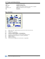
User interface
(1)
(2)
(3)
(4)
(5)
(6)
(7)
(8)
(9)
(10)
:
:
:
:
:
:
:
:
:
:
Main menu bar; toggles between main menu and current screen;
Main menu;
submenu (if applicable);
current or chosen position in the submenu;
current or chosen position in the main menu;
Title bar, current page/unit, total available pages/unit’s;
display with chosen options or relevant information;
page/unit back;
page/unit forward;
The lower bar toggles an extra function, if applicable.
Corrosion & Water-Control bv
ICAF User manual Clients 2.0 Eng.
Page 8
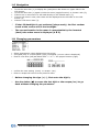
1.G Navigation
•
•
•
•
•
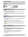
Touch the menu bar (1) to display the (main)menu bar shown on upper side on the
LCD screen;
Touch the menu bar (1) again to hide the menu (toggle function) or choose a tab (2);
If there are no sub menu’s it will lead directly to the related menu (7);
If more sub menu’s exist, then these will be displayed at the left side on the LCD
screen (3);
Choose a sub menu item (3).
*
If the LCD backlight is not activated (sleep mode), the first random
touch at the screen will lit the backlight.
&
The current location in the menu is recognizable by the inverted
(dark) tabs when menu is displayed (4 & 5).
1.H Changing parameters
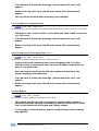
• Select a parameter value displayed on the screen
• A keypad (left) or a chose panel (right) will appear (current value is displayed)
• Enter a new value (left) or Select with “<” or “>” the proper function (right)
• confirm the new setting (enter) or escape (esc)
• Enter or escape will return to the previous menu
*
Before changing the sign (+/-), first enter the digit’s;
&
Use the delete (Å) to erase the last digit or the escape (esc) to go
back without changing the parameter.
Corrosion & Water-Control bv
ICAF User manual Clients 2.0 Eng.
Page 9
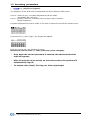
1.I Accessing parameters
(?), (logon) or (Logout)”
The operation of this ICAF unit is categorized into three different USER levels:
Level 0: read-out only, no system adjustments can be made (Accessable for everyone);
Level 1: primary functions; to access this level a pin code is needed –
(Ships engineers);
If system adjustments must be made, a pin code is required to access the specific menu.
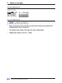
First touch the (?) then “login”, the keypad will appear
Enter the correct pin code followed by enter:
Default pin code for level 1 = 1234 (PIN code can be changed);
*
Only when the correct password is entered, the advanced function
tabs will appear;
*
After 15 minutes of no activity on the touch screen, the system will
automatically log off;
*
To excess other levels, first log out, then repeat login.
Corrosion & Water-Control bv
ICAF User manual Clients 2.0 Eng.
Page 10
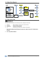
1.J Menu flow diagram
1.K Main menu tabs
The main menu consists of the following items, displayed with tabs:
1.
2.
3.
4.
(Status)
(System)
(Hardware)
(?)
Status displays and sets the anode values ;
General system settings;
Hardware configuration;
Logon/log off, product & customer information.
*
Use the backward and forward arrows to select the unit in the status
screen.
1.0.1.0) Menu Status.
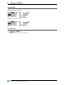
Corrosion & Water-Control bv
ICAF User manual Clients 2.0 Eng.
Page 11
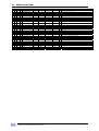
1.L Menu overview
M
S
P
L
(English)
Unit
Min
Max
Default
Lv
1
1
0
0
1
1
0
1
Status display
Alarms
UNIT
NA
1
NA
7
NA
1
NA
0
0
1
1
1
1
status
select
On
OFF
On
1
2
2
2
0
1
1
0
1
1
0
1
2
systemsettings
Date/time
Language
date
select
YY/MM/DD
EN
HH:MM
EN
1
1
2
1
1
3
Alarm relays
select
Error ON
Error OFF
n/a
EN
Error
OFF
2
2
2
3
3
3
0
1
1
0
1
2
Logs
View log
Clear log
NA
NA
NA
NA
NA
NA
NA
NA
NA
NA
NA
NA
0
0
0
Displays most recent alarms /event logs (max.100)
3
3
3
3
3
3
3
4
4
4
4
4
4
4
0
1
1
1
1
1
1
0
1
2
3
4
5
6
SD
Make log
Export log
Import configuration
Export configuration
Import Language
Reboot
NA
NA
NA
NA
NA
NA
NA
NA
NA
NA
NA
NA
NA
NA
NA
NA
NA
NA
NA
NA
NA
NA
NA
NA
0
1
0
1
0
1
0
SD card import/export, log- and system dump
Makes current situation log and collect it on the SD-card
Copies the complete event/alarm log on the SD-card
Imports all settings from the SD-card
Copies all settings on the SD-card
Imports a language file from the SD-card
Reboot the system to reset or update
4
4
4
4
4
0
1
2
3
4
0
1
1
1
1
0
0
0
0
0
Information (?)
Login/Logout
Info
About
Activation
num
info
info
num
1
NA
NA
NA
999999999
NA
NA
NA
level 0
NA
NA
NA
0
0
0
1
Corrosion & Water-Control bv
ICAF User manual Clients 2.0 Eng.
Remark
Overview screen per unit
Overview of alarms
import other language from sd card
1
Page 12
2
Principle of the ICAF system
ICAF is an abbreviation of Impressed Current Anti Fouling. It’s basic function is to prevent
biological marine growth in cooling systems.
Barnacles, mussels, algae, and other types of shellfish grow in the cooling system and thus
adversely affect it’s functioning. Vessels operating in coastal water run the greatest risk of
being polluted by fouling.
This very reliable and sophisticated ICAF system is a highly effective option to prevent this
kind of fouling.
It’s functional principle is based on an artificially triggered voltage difference between the
copper anodes and a suitable cathode. This causes a minor electric current to flow from
the anodes, so that they are dissolved to a certain degree.
The control unit of this ICAF system (The Digital Processing Unit), offers a number of
control functions to make sure that the anodes add the required minimum amount of
copper particles to the sea water. This process ensures the formation of copper (I) oxide
and creates ambient conditions to prevent foulin from nesting inside the cooling systems.
In some cases aluminium or iron anodes are used beside the copper anodes. The function
of those aluminium and iron anodes is to avoid corrosion damage in the connected/related
pipe work.
This ICAF system can interact with the ship’s management system to show alarms and
current values. The ICAF system can also interact with sea water pumps.
Therefore, perfect protection is guaranteed under all conditions and the amount of
dissolved copper is minimised to prolong the lifetime of the anodes.
Corrosion & Water-Control bv
ICAF User manual Clients 2.0 Eng.
Page 13
3
Status menu
1.0.0.0) Status
panel overview
The following screen will appear when the system is operating properly and no alarms are
active.
1.0.1.0) Status panel
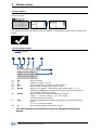
(status)
(1)
(2)
(3)
(4)
(5)
ID
#
Set
V
01/01
(6)
Alarm
(7)
line
(8)
A
*
:
:
:
:
:
anode number
setpoint number (I or II)
current setpoint or status (e.g. Off, Pause)
actual anode voltage measured in volts.
page x of xx pages, * Alternating with alarm bells (/)
indicates a new alarm. selecting the alarm bells will navigate to
an extended information panel.
: alarm column shows active alarms per anode:
Codes: = alarm indicator, 15 = error code.
Alarms & alarm settings
: select the appropriate anode to navigate to the anode settings
panel.
1.0.1.0) Anode settings
: actual anode power measured in amps.
Use the backward and forward arrows to navigate through the
panels.
Corrosion & Water-Control bv
ICAF User manual Clients 2.0 Eng.
Page 14
4
Menu system/settings
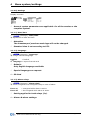
2.1.0.0) Settings
Display overview
*
General system parameters are applicable for all the anodes or the
complete system.
2.1.1.1) Date/time
(Settings), “Date/time”
# adjustment of date and time
*
Attention:
The timestamp of previous made logs will not be changed.
*
Standard time is set according to UTC.
2.1.1.2) Language
(Settings), “Language”
# change interface language
English
= Default
2nd language = import from sd card
*
Default:
Only English language available.
*
Special languages on request.
SD Card
2.1.1.3) Alarm relays
(Settings), “Alarm relais”
# select energized or de-energized relays in case of alarm.
Error on
Error off
*
= energized while alarm is active
= de-energized while alarm is active
Setting applies for both relays (2x).
Alarms & alarm settings.
Corrosion & Water-Control bv
ICAF User manual Clients 2.0 Eng.
Page 15
5
Menu system/Log
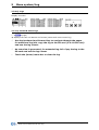
2.3.0.0) Logs
Display overview
2.3.1.0) events & alarm logs
(Logs)
# displays the last 100 alarms and events (starts with most recent log)
*
Use the backward and forward key to navigate through the pages
for additional log info, copy the log to the SD card (2.4.1.0-SD card)
and use the log viewer.
*
An overview is generated, for extended log info. Copy the log to the
SD card and use the log viewer.
&
Touch the (lower) menu bar to clear the log.
Corrosion & Water-Control bv
ICAF User manual Clients 2.0 Eng.
Page 16
6
Menu System/SD
2.4.0.0) SD
Display overview
2.4.1.1) Make a system log instantly (level 1)
(SD), “make log”
# touching the button will make a log instantly
*
The log is saved to the internal memory. Use 2.4.1.2) export log to
export copy a for export to SD card.
&
When inserting a SD-card, the SD main menu will automatically be
displayed.
2.4.1.2) Export log
(SD), “export log”
# export the internal log files on SD card
*
Filename is the “serial number” of the DPU unit with “CWL” extension,
e.g. 1234.cwl.
*
Exporting the log will NOT clear de log. It’s only a copy!
*
If no SD card is found, the message “please insert SD-card” will be
displayed.
&
When inserting a SD-card, the SD main menu will automatically be
displayed.
2.4.1.3) Import a configuration file (level 1)
(Unit), (SD), “Import cnf.”
# Import a configuration file from SD card with settings (serial number.
*
Insert an SD card containing the correct configuration file. This files
should consist a name equal with the serial number of the DPU and
have a .CWS extension
*
Be sure that SD card contains not an update file (AT1440.alf)
*
After successful import of the file, the system will reboot
automatically
Corrosion & Water-Control bv
ICAF User manual Clients 2.0 Eng.
Page 17
*
If no SD card is found, the message “please insert SD-card” will
appear.
&
When inserting a SD-card, the SD main menu will automatically
appear.
*
The log will be cleared after importing new settings!
2.4.1.4) Export a configuration file
(Unit), (SD), “Export cnf.”
# export (copy) all the settings and configuration parameters of the system on a SD card
*
Filename is the “serial number” of the DPU unit with “CWS” extension,
e.g. 1234.cws.
*
If no SD card is found, the message “please insert SD-card” will
appear.
&
When inserting a SD-card, the SD main menu will automatically
appear.
2.4.1.5) Import second language file (level 1)
(Unit), (SD), “Import lng”
# Import a predefined language file form SD to the DPU
*
Insert an SD card containing the correct language file. This files
should consist a name equal with the serial number of the DPU and
have a .cwt extension.
*
After successful import of the file, the system will switch to the
second language automatically.
*
If no SD card is found, the message “please insert SD-card” will
appear.
&
When inserting a SD-card, the SD main menu will automatically
appear.
2.4.1.6) Reboot
(Unit), (SD), “Reboot”
# reboot the system without the need to power down
*
This option can also be used to trigger an update while system is
powered: Slide the SD card (containing a newer version file) into the
slot, the SD functions will popup and choose reboot.
&
It is strongly recommended to export configurations before making
any updates.
Corrosion & Water-Control bv
ICAF User manual Clients 2.0 Eng.
Page 18
7
Menu (?)/Login
4.1.0.0) Login/log off
Display overview
4.1.1.0) Login/log off
(?), (login) of (Logout)”
# Login to excess level specific functions
*
After 15 minutes of no activity on the touch screen, the system will
automatically log off (level 0);
*
To excess other levels, first log out, then repeat login;
*
Default pin code for level 1 = 1234;
Corrosion & Water-Control bv
ICAF User manual Clients 2.0 Eng.
Page 19
8
Menu (?)/Info
4.1.2.0) Info
Display overview “Level 0”
Display overview “Level 1”
4.1.2.0) Info
(?), (Info)
# Serial number & version information
Corrosion & Water-Control bv
ICAF User manual Clients 2.0 Eng.
Page 20
9
Menu (?)/About
Display overview “Level 0”
Display overview “Level 1”
4.1.3.0) About
(?), (about)
# customer & system information
Corrosion & Water-Control bv
ICAF User manual Clients 2.0 Eng.
Page 21
10 Menu (?)/Activation
The system is carefully designed to guarantee its function between two dry-dock periods,
with almost no maintenance. The lifetime of the anodes is based on the information given
by the shipyard or ship owner. The almost complete dissolved anodes should be changed
during a dry-dock period, with original spare anodes only.
After commissioning the ICAF system should by activated with a special key, which can be
obtained by internet. The expire date of this code is equal to a dry-dock period (lifetime of
the anodes), plus a safety margin.
Before expiration, the system will generate a pre-alarm and show the remaining lifetime of
the anodes, thus before maintenance is required.
The set point of this pre-alarm is set to assure plenty of time to schedule maintenance and
arrange the necessary original (spare) parts.
The system will repeat the pre-alarm a few times.
After installation of the original anodes, the system should by activated again with a
special code, which can be obtained by internet.
To avoid any damage on the vessel, the system will shut down completely.
To
•
•
•
•
view the remaining period or to enter a new activation key:
login to level 1;
Proceed to the activation menu;
The screen shows the original period (current activation time) and the remaining time;
•
•
To obtain an activation code, note the serial number of the DPU (Snr.) and the system
code (Sys.code);
Visit the website of Corrosion & Water Control bv (www.corrosion.nl), to fill in above
mentioned numbers to obtain the activation key;
Touch the “enter activation key” and enter the new activation key;
The system is now activated and ready to use.
*
Attention; A locked DPU can only be unlocked with a valid activation key!
*
After entering a new activation code, the remaining time will be
overruled. The new entered period will start immediately.
•
When the system is activated you are able to make use of our worldwide service network.
All service engineers have easy access to all relevant details of the system when activated,
so fast and determined action can be taken when required. With this feature we try to
reduce the installation of non-original parts, which can affect the function of our system.
Corrosion & Water-Control bv
ICAF User manual Clients 2.0 Eng.
Page 22
11 Understanding the software
DPU
The DPU (digital processor unit) consist of a LCD display provided with a touch screen and
a microprocessor controller.
The DPU is capable to control 16 ICAF cards, which offers 64 individual controlled 1,1Amp
(@10 volt) outputs.
The DPU is also provided with 4 configurable inputs. These inputs control the current of
the specific anodes between the lower or higher setpoint. This can be used to extend the
lifetime.
The DPU can be installed in the ICAF cabinet or separate (e.g. control room).
The DPU can be installed in one of the unit cabinets or separate (e.g. control room).
Anode settings
The following settings can be made for every anode:
Status
on/off = to activated or de-activated the specific anode.
setpoints
Setpoint I
Setpoint II
=
=
The normally required power in amps.
Used when High/Low function is activated.
Switching setpoints.
Polarity level
Every time the primary voltage is reconnected the system will check the potentials of all
anodes (in unpowered state)
Copper anodes have a typical expected potential of +300mV. A value -300mV indicates
that the anode is wrong connected, while a value of +100mV indicates that the anode
material is not copper. In these cases the system will generate an alarm and prevent the
activation of this anode to avoid any damage.
When the installation is corrected, a restart of the system will activate the specific
anode(s) again.
Output configuration
Every available channel delivers maximal 1,1 amps @ 10volts. It can be used as a single
anode. When more power (Amp) is required, more channels can be combined to one
installation manual). The channels
anode in order the reach the required power. (
should be appointed to the specific anode (output).
Corrosion & Water-Control bv
ICAF User manual Clients 2.0 Eng.
Page 23
12 Understanding the software
switching setpoints
The system is provided with a second setpoint parameter per anode. This feature can be
very useful when the water intake fluctuates strongly in volume. For instance, use the first
setpoint for normal operation and the second (lower) setpoint in cases of minor volume
water consumption. This feature assures a minimum use of power and extend the lifetime
of the anodes.
Switching between the setpoints is utilized by four inputs. Each input can be configured to
one or more anodes. Connect the input to a remote switch or better; to a potential free
contact which indicates that the concerning system (pump) on or off to regulate
automatically switching between the setpoints.
To connect the input to a (remote) device
Corrosion & Water-Control bv
ICAF User manual Clients 2.0 Eng.
installation manual.
Page 24
Alarms & alarm settings
The ICAF system can compromise extensive monitor & alarming features.
The alarm monitor is divided in two parts:
1. Monitoring the performance of the system, e.g. communication, correct outputs and
inputs signals.
2. Exceeding of set limits, e.g. amps, resistance, etc.
The ICAF system has enough space to log at least 15000 alarms and
events in its memory.
*
If an alarm is activated the following actions will take place:
1. the alarm code will be displayed;
2. the system will log the alarm, with all relevant information;
3. the alarm relays will be activated.
An alarm should be acknowledged.
*
All the alarms (except system errors) are individual provided with
•
adjustable upper and/or lower limit’s
•
on/off (or set to “0”) when the specific options is not used
alarm codes
The log screen displays the last 100 alarm records, sorted by date with the most recent on
top.
All lines starts with a timestamp followed by a code. The code represents the following
information:
Example : 07/12/31 13:48 | ÇA01.09
07/12/31 13:48 Time stamp
| separator
Ç start/end alarm
A source of alarm
01 unit number
09 alarm code
YY/MM/DD UU:MM
Ç = start alarm
È = end alarm
A = Anode
G = general
only in case of unit
see table alarm code
Table alarm code
Code
Error/Warning
A/G
Description
04
Short circuit
(Anode) Check anode cable and/or anodes constructions
05
High resistance
(Anode) Warn out anode(s) or open circuit(s)
06
Below setpoint
(Anode) Output failure or to high resistance
10
Communication error
(global) Communication problem between DPU and one or
more cards
15
Polarity error
(Anode) Wrong polarity. Connection or improper type anode
Corrosion & Water-Control bv
ICAF User manual Clients 2.0 Eng.
Page 25
alarm relays
The system includes two double poled relays for respectively alarm notification to third
party equipment and indication of the system status.
Both relays will be activated whenever an alarm occurs. The first relay will be de-activated
after acknowledgement, while the second relay stays active as long as the alarm situation
remains.
The function 2.1.1.3) alarm relays provides the choice whether, the relays should be
energized (normally de-energized) or vice versa. Together with both normally open or
closed hardware connections available, a variety of function can be made, depended on
the requirement.
While an alarm is not (yet) acknowledged, the first relays will stay active. In order to be
notified of other alarms.
*
“normally open” and “normally closed” contacts are in perspective of
a de-energized relays.
The recommended connection is a de-energized relays connected to the normally open
contacts. In order to have a “fail safe” alarm which will set the alarm in case of power
interruption or broken wires.
Functions of the alarm relays:
2.1.1.3) alarm relays
Defines energized or de-energized relays function
during alarm.
For a complete understanding of the alarm behaviour, we refer to the
following schematic overview;
Corrosion & Water-Control bv
ICAF User manual Clients 2.0 Eng.
Page 26
Event & alarm logging
The DPU is equipped with an internal flash memory, which offers space for 15000 alarms,
events or data logs.
The internal flash mechanism works on FI-FO (First In - First Out). After complete filling of
the memory the oldest log will be replaced by a new one.
There are 4 types of logs:
1. Data logs
: general daily log of the performance of the ICAF system;
2. Alarm logs : error code including time stamp and source of the alarm;
3. System log : system dump of current hard and software situation, especially for
debug hard & software purposes;
4. Event logs : to monitor changes at the system like startup.
*
The last 100 alarm logs (including startup event log) can be displayed in
the display provided with timestamp.
*
Clearing the alarms in the display will not delete the logs in the flash
memory.
*
To copy logs onto a SD card
SD Card
SD Card
The back of the DPU is provided with a SD-card slot.
The SD card is used for update the system and import/export data form and into the
system.
*
The SD card must be formatted with a 6 byte fat system. This can be
achieved by any computer with a Windows™ operating system with a SD
card slot.
Import/export data
When sliding a SD Card in the slot, while the system is powered, the DPU will
automatically detect the presents and trigger the SD card menu (2.4.0.0)
This menu shows the following options:
Make log
: instantly make a system dump (internal memory!)
Export Log
: copies the TOTAL log (including a system dump) on SD card.
Import language
: import a second language from sd card (future option)
Update the ICCP
To update the ICCP system;
• Copy the update file (xxx.alf file) on to the SD card.
• be sure the system is unpowered.
• Slide the SD card into the slot
• Power the system
• The screen shows the status of the update import and will start automatically after
finishing the update. (don’t interrupt this process!)
• Check the settings and adjust were needed.
*
Attention :
In case of new release with additional functions, parameters and
configurations will be set as factory defaults. Be sure to have a backup of
all the settings and configurations and the knowledge to adjust these.
Corrosion & Water-Control bv
ICAF User manual Clients 2.0 Eng.
Page 27