1
Micriµm
© Copyright 2006, Micriµm
All Rights reserved
µC/Modbus
V2.10
(µC/Modbus-S and µC/Modbus-M)
User’s Manual
www.Micrium.com
µC/Modbus
Table of Contents
Revision History .............................................................................. 5
1.00
1.01
1.02
Introduction ..................................................................................... 6
Topologies....................................................................................... 8
µC/Modbus Architecture............................................................. 10
2.00
2.01
2.02
2.03
2.04
Directories and Files ..................................................................... 13
Directories and Files, Target Independent Source Code .............. 13
Directories and Files, RTOS Interface........................................... 13
Directories and Files, Product Specific Files ................................. 14
Directories and Files, CPU and Compiler Specific Files................ 14
3.00
3.01
3.02
3.03
3.04
3.05
3.06
3.07
3.08
3.09
3.10
3.11
3.12
3.13
3.14
3.15
3.16
3.17
3.18
3.19
Using µC/Modbus....................................................................... 16
Using µC/Modbus, MB_CfgCh()................................................. 18
Using µC/Modbus, MB_ChToPortMap()..................................... 20
Using µC/Modbus, MB_Exit() ..................................................... 21
Using µC/Modbus-M, MBM_FC01_CoilRd() .............................. 22
Using µC/Modbus-M, MBM_FC02_DIRd()................................. 24
Using µC/Modbus-M, MBM_FC03_HoldingRegRd() ................. 26
Using µC/Modbus-M, MBM_FC03_HoldingRegRdFP() ............. 28
Using µC/Modbus-M, MBM_FC04_InRegRd()........................... 30
Using µC/Modbus-M, MBM_FC05_CoilWr() .............................. 32
Using µC/Modbus-M, MBM_FC06_HoldingRegWr() ................. 34
Using µC/Modbus-M, MBM_FC06_HoldingRegWrFP() ............. 36
Using µC/Modbus-M, MBM_FC08_Diag() ................................. 38
Using µC/Modbus-M, MBM_FC15_CoilWr() .............................. 40
Using µC/Modbus-M, MBM_FC16_HoldingRegWrN () .............. 42
Using µC/Modbus-M, MBM_FC16_HoldingRegWrNFP() .......... 44
Using µC/Modbus, MB_Init() ...................................................... 46
Using µC/Modbus, MB_ModeSet()............................................. 47
Using µC/Modbus-S, MB_NodeAddrSet().................................. 48
Using µC/Modbus-S, MB_WrEnSet()......................................... 49
2
µC/Modbus
4.00
4.01
4.02
4.03
4.04
4.05
4.06
4.07
4.08
4.09
4.10
4.11
4.12
4.13
4.14
4.15
4.16
4.17
4.18
4.19
4.20
Configuring µC/Modbus ............................................................. 50
Configuring µC/Modbus, MODBUS_SLAVE_EN ....................... 50
Configuring µC/Modbus, MODBUS_MASTER_EN .................... 50
Configuring µC/Modbus, MODBUS_ASCII_EN.......................... 50
Configuring µC/Modbus, MODBUS_RTU_EN............................ 51
Configuring µC/Modbus, MODBUS_MAX_CH ........................... 51
Configuring µC/Modbus, MODBUS_BUF_SIZE......................... 51
Configuring µC/Modbus, MODBUS_FP_EN .............................. 51
Configuring µC/Modbus, MODBUS_FP_START_IX .................. 51
Configuring µC/Modbus, MODBUS_FC01_EN .......................... 52
Configuring µC/Modbus, MODBUS_FC02_EN .......................... 52
Configuring µC/Modbus, MODBUS_FC03_EN .......................... 52
Configuring µC/Modbus, MODBUS_FC04_EN .......................... 52
Configuring µC/Modbus, MODBUS_FC05_EN .......................... 52
Configuring µC/Modbus, MODBUS_FC06_EN .......................... 52
Configuring µC/Modbus, MODBUS_FC08_EN .......................... 53
Configuring µC/Modbus, MODBUS_FC15_EN .......................... 53
Configuring µC/Modbus, MODBUS_FC16_EN .......................... 53
Configuring µC/Modbus-S, MODBUS_FC20_EN ...................... 53
Configuring µC/Modbus-S, MODBUS_FC21_EN ...................... 53
Configuring µC/Modbus, RAM Memory Requirements .............. 54
5.00
5.01
5.02
5.03
5.04
5.05
5.06
5.07
5.08
5.09
5.10
5.11
µC/Modbus-S, Accessing application data................................. 55
µC/Modbus-S, MB_CoilRd()....................................................... 56
µC/Modbus-S, MB_CoilWr()....................................................... 58
µC/Modbus-S, MB_DIRd() ......................................................... 60
µC/Modbus-S, MB_InRegRd() ................................................... 62
µC/Modbus-S, MB_InRegRdFP()............................................... 64
µC/Modbus-S, MB_HoldingRegRd() .......................................... 66
µC/Modbus-S, MB_HoldingRegRdFP()...................................... 68
µC/Modbus-S, MB_HoldingRegWr() .......................................... 70
µC/Modbus-S, MB_HoldingRegWrFP() ..................................... 72
µC/Modbus-S, MB_FileRd() ....................................................... 74
µC/Modbus-S, MB_FileWr() ....................................................... 76
3
µC/Modbus
6.00
6.01
6.02
6.03
6.04
6.05
6.06
6.07
6.08
6.09
6.10
6.11
Board Support Package (BSP)...................................................... 78
BSP, MB_CommExit()................................................................... 78
BSP, MB_CommPortCfg() ............................................................ 79
BSP, MB_CommRxTxISR_x_Handler() ........................................ 80
BSP, MB_CommRxIntEn() ............................................................ 81
BSP, MB_CommRxIntDis() ........................................................... 81
BSP, MB_CommTx1()................................................................... 81
BSP, MB_CommTxIntEn() ............................................................ 82
BSP, MB_CommTxIntDis() ........................................................... 82
BSP, MB_RTU_TmrInit()............................................................... 83
BSP, MB_RTU_TmrExit() ............................................................. 83
BSP, MB_RTU_TmrISR_Handler() ............................................... 83
7.00
7.01
7.02
7.03
7.04
7.05
RTOS Interface ............................................................................. 84
RTOS Interface, MB_OS_Init() ..................................................... 87
RTOS Interface, MB_OS_Exit() .................................................... 88
RTOS Interface, MB_OS_RxSignal() ............................................ 89
RTOS Interface, MB_OS_RxWait()............................................... 90
RTOS Interface, Configuration ...................................................... 91
8.00
8.01
8.02
8.03
8.04
µC/Modbus Program Flow.......................................................... 92
µC/Modbus-S, ASCII Rx and Tx ............................................... 93
µC/Modbus-S, RTU Rx and Tx ................................................. 95
µC/Modbus-M, ASCII Rx and Tx .............................................. 97
µC/Modbus-M, RTU Rx and Tx ................................................ 99
9.00
Acronyms, Abbreviations and Mnemonics .................................. 101
Licensing ..................................................................................... 103
References.................................................................................. 103
Contacts...................................................................................... 103
4
µC/Modbus
Revision History
Version
Date
V1.00
2004/09/08
Initial Release
Description
V1.61
2005/07/29
Converted code to use µC/CPU files.
Removed dependencies on ‘stdlib’ functions.
Improved the architecture.
V2.00
2006/05/15
Simplified the code.
Made error return codes 16 bits instead of 8.
Added support for Modbus Master.
V2.10
2006/08/10
Corrected bug with Modbus ASCII LRC calculation. LRC was being
computed on ‘binary’ data instead of the raw ASCII message. Our test tool
was incorrectly calculating LRCs on the binary data and we followed the
same scheme.
Removed all calls to MB_TxErrChkCalc() since the LRC and CRC
calculations for Tx are done just before transmitting the response.
5
µC/Modbus
1.00
Introduction
This document describes µC/Modbus, which implements the Modicon Modbus
Protocol (referred to as Modbus) along with the “Daniel’s Extension” to the Modbus
protocol, as specified by Daniel Flow Products.
For more details on the Modbus protocol, please refer to Modicon’s:
Modicon Modbus Protocol Reference Guide
PI–MBUS–300 Rev. J
The Modbus protocol consists of the reception and transmission of data, in predefined
packets, hereby referred to as “frames”. There are two types of frames that the Modbus
protocol operates with, an ASCII frame, and a Remote Terminal Unit (RTU) frame. The
ASCII frame is a frame based on ASCII hexadecimal characters, while the RTU frame is
strictly a binary implementation. ASCII mode is easier to implement and debug but
offers roughly half the data transfer speed of RTU mode. With µC/Modbus you can
use either mode since implementation and testing has been done by Micrium.
µC/Modbus can support any number of communication channels. The mode of
operation on each channel can either be ASCII or RTU and is selectable on a per
‘channel’ basis.
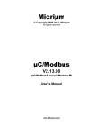
Figure 1-1 shows the relationship between a product designed using µC/Modbus and
other Modbus masters and slaves products. The ‘Serial Channels’ are typically
RS-232C or RS-485 asynchronous serial interfaces typically using a UART (Universal
Asynchronous Receiver Transmitter).
Modbus
Master
(i.e. Client)
Serial Channels
(RS-232C or RS-485)
Your Product
(Running µC/Modbus)
Modbus Master/Slave
Modbus
Slave
(i.e. Server)
Figure 1-1, Relationship between Modbus-based products.
6
µC/Modbus
Masters (also known as Clients) initiate all data transfers to one or more Slaves (also
known as Servers) in a system. In other words, only a Master (Client) can read or write
values from/to a Slave (Server).
µC/Modbus can be made to look like having multiple master or slave ports. In fact,
µC/Modbus allows you to have a combination of up to 250 master or slave ports from
a single target system!
µC/Modbus-S indicates that your product contains the Modbus slave implementation
of µC/Modbus and, µC/Modbus-M indicates that your product contains the Modbus
master implementation of µC/Modbus.
You should note that a product can contain both µC/Modbus-S and µC/Modbus-M
at the same time. However, the master and the slave would be on separate ports.
7
µC/Modbus
1.01
Topologies
Figure 1-2 shows the relationship between multiple products (slaves) and a Modbus
master (assuming RS-485).
Modbus
Master
RS-485 Bus
Your Product
Your Product
Your Product
(Running µC/Modbus-S)
(Running µC/Modbus-S)
(Running µC/Modbus-S)
Figure 1-2, Relationship between Modbus Master and Slaves on RS-485 Network.
Figure 1-3 shows the relationship between multiple products (slaves) and multiple
Modbus masters (assuming RS-485 in the example) with one of those products being
µC/Modbus-M. You will note that only one master can be present on each RS-485
network.
Modbus
Master
Your Product
(Running µC/Modbus-M)
RS-485 Bus
RS-485 Bus
Your Product
Your Product
(Running µC/Modbus-S)
(Running µC/Modbus-S)
Figure 1-3, Multiple Modbus Masters and Slaves on RS-485 Networks.
8
µC/Modbus
Figure 1-4 shows the relationship between multiple products (slaves) and multiple
Modbus masters (assuming RS-232C in the example). As you can see, with RS-232C,
each master needs to have a direct connection to each slave. µC/Modbus supports
this topology since each product can have multiple communication channels. Although
RS-232C requires more point-to-point connections, it offers the benefit of higher
throughput since communications can occur concurrently instead of sequentially.
Modbus
Master
Modbus
Master
RS-232C Interfaces
RS-232C Interfaces
Your Product
Your Product
(Running µC/Modbus-S)
(Running µC/Modbus-S)
Figure 1-4, Multiple Modbus Masters and Slaves with RS-232C.
Modbus allows you to read or write integer, floating-point (assuming the Daniels
Extensions) and discrete values from/to your target system. µC/Modbus can read or
write from/to:
up to 65536 16-bit integer values,
up to 65536 32-bit floating-point values,
up to 65536 coils, and
up to 65536 discrete inputs.
Integer and floating-point requests may not be mixed in the same command. Multiple
integer values (up to 125) and multiple floating-point values (up to 62) may be written
via a single command.
Depending on the processor you are using, you should be able to run µC/Modbus with
data rates from 9600 up to 256,000 baud. The baud rate you can attain is actually
limited to the performance of the CPU and not µC/Modbus.
9
µC/Modbus
1.02
µC/Modbus Architecture
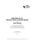
Figure 1-5 shows how the µC/Modbus communications stack fits in your product and
also shows which source files are associated with each layer.
MB stands for ModBus, MBS stands for ModBus Slave and MBM stands for ModBus
Master. A file that starts with MB_ indicates that the code in the file is independent of
Modbus Slave or Master. A file that starts with MBS_ contains Modbus Slave specific
code and, of course, a file that will start with MBM_ will contain MODBUS Master specific
code.
F1-5(1)
Your product needs to configure µC/Modbus (at compile time) to
establish the maximum number of channels your product will support,
whether some channels will support Modbus ASCII and/or RTU, whether
the ‘Daniels Extensions’ will be supported to provide floating-point, which
Modbus function codes will be supported, whether a product will be a
Master, a Slave or both, etc. Configuration is done by changing a C
header file (MB_CFG.H). This is code that YOU need to provide and
MB_CFG.H typically resides in your product’s directory since it can be
different for each product.
F1-5(2)
A Modbus master, connected to your product (that is running
µC/Modbus-S) can read or change just about ANY data in your
application. Access to your data (read or write) is done via a C file that
you provide (MB_DATA.C). MB_DATA.C can read integers, coils, discrete
inputs, floating-point values, etc. MD_DATA.C also allows you to execute
ANY code when data is read or written. For example, if you change the
diameter of a circle and need to compute the surface, you can simply
include the code to compute the surface in MB_DATA.C. More on this
later. This is code that YOU need to provide and MB_DATA.C typically
resides in your product’s directory since it can be different for each
product.
F1-5(3)
This is the application independent slave code and it knows how to
process Modbus ASCII and/or Modbus RTU packets. You should NOT
have to modify this code.
F1-5(4)
The interface to the UARTs in your product is placed in the Board Support
Package (BSP) file called MB_BSP.C. This is a file that you provide in
order to interface to µC/Modbus. Note that each channel can either
communicate via RS-232C or RS-485 (at the interface level). This is code
10
µC/Modbus
that YOU need to provide and MB_BSP.C is either placed in your product’s
directory or provided by Micrium in the
\Micrium\Software\uC-Modbus\Ports\<CPU>\<compiler>
directory. This is the adaptation layer for the CPU or board you are using.
(1)
Your Application
MB_CFG.H
(2)
Data Access
MB_DATA.C
(6)
CPU Interface
CPU*.*
µC/Modbus
(3)
(4)
MB.C and MB.H
MB_DEF.H
MB_UTIL.C
MBS_CORE.C
MBM_CORE.C
MBS_ASCII.C
MBS_RTU.C
UART Driver
(5)
MB_BSP.C
UART
(RS-232C or RS-485)
Figure 1-5, Relationship between modules.
11
RTOS Interface
MB_OS.C
µC/Modbus
F1-5(5)
µC/Modbus assumes the presence of an RTOS (Real-Time Operating
System). However, you can use just about any RTOS and the RTOS
specifics are actually isolated in a file called MB_OS.C. The code for
µC/OS-II is provided so you don’t have to change this code if you use
µC/OS-II in your product.
F1-5(6)
µC/Modbus is independent of the CPU and the compiler you use.
However, you need to provide information about the data types specific to
your CPU and compiler. For example, you need to define the following
data types:
CPU_BOOLEAN
CPU_INT08U
CPU_INT16U
CPU_INT32U
CPU_FP32
Etc.
Boolean (True or False, Yes or No, etc.)
8 bit unsigned integer
32 bit unsigned integer
8 bit unsigned integer
32 bit IEEE754 floating-point
These data types are needed because µC/Modbus never uses the
standard C data types (i.e. char, short, int, long, etc.) because they
are non-portable.
These data types need to be placed in a file called CPU.H (more on this
later).
12
µC/Modbus
2.00
Directories and Files
The code for µC/Modbus is found in the following directories.
2.01
Directories and Files, Target Independent Source Code
\Micrium\Software\uC-Modbus\Source
This directory contains the UART, OS and CPU independent source files. This
directory contains the following files:
2.02
MB.C
MB.H
MB_DEF.H
MB_UTIL.C
Master/Slave independent
MBS_CORE.C
Slave specific code
MBM_CORE.C
Master specific code
Directories and Files, RTOS Interface
\Micrium\Software\uC-Modbus\OS\uCOS-II
This directory contains the code to interface to the µC/OS-II RTOS and contains
the following file:
MB_OS.C
(See Section 7.00)
If you interface µC/Modbus to a different RTOS, you would place an MB_OS.C
file in a separate directory. In other words, all RTOS interface files should be
called MB_OS.C but the specifics of the actual RTOS you use would be placed in
a different directory. When you build your product, you obviously need to select
only one RTOS interface – the one specific to your RTOS.
13
µC/Modbus
2.03
Directories and Files, Product Specific Files
???\Product
This directory contains your application code. You need to provide the following
files:
(See Section 4.00)
(See Section 5.00)
(See Section 6.00)
MB_CFG.H
MB_DATA.C
MB_BSP.C
2.04
Directories and Files, CPU and Compiler Specific Files
\Micrium\Software\uC-CPU\<CPU-type>\<compiler>
This directory contains information about your CPU and the compiler you are
using. There are three files that you need to specify:
cpu.h
cpu_a.asm
It’s preferable to ‘modify’ existing files than create new ones from scratch so that
you don’t forget anything.
An example of these files is provided with
µC/Modbus.
cpu.h
This file defines CPU/compiler specific data types. The code below shows an
example of the data types needed by µC/Modbus for an ARM CPU and the IAR
Embedded Workbench compiler.
typedef
typedef
typedef
typedef
typedef
typedef
typedef
typedef
typedef
typedef
typedef
typedef
unsigned
unsigned
unsigned
signed
unsigned
signed
unsigned
signed
void
char
char
char
char
short
short
int
int
float
double
void
CPU_VOID;
CPU_CHAR;
CPU_BOOLEAN;
CPU_INT08U;
CPU_INT08S;
CPU_INT16U;
CPU_INT16S;
CPU_INT32U;
CPU_INT32S;
CPU_FP32;
CPU_FP64;
(*CPU_FNCT_PTR)(void *);
14
µC/Modbus
You also need to specify the type of ‘alignment’ to use as well as the
‘endianness’ of the processor:
#define
#define
CPU_CFG_ALIGN_TYPE
CPU_CFG_ENDIAN_TYPE
CPU_ALIGN_TYPE_32
CPU_ENDIAN_TYPE_LITTLE
You also need to define code to disable and enable interrupts. In fact, the code
to disable interrupts should ‘save’ the state of the interrupt enable setting and
then disable interrupts. This is done by an assembly language function called
CPU_SR_Save(). The code to re-enable interrupts should simply restore the
state saved by CPU_SR_Save(). This would be done by a function called
CPU_SR_Restore(). The state of the interrupt enable setting is stored in a
local variable of type CPU_SR as shown below.
typedef
CPU_INT32U
CPU_SR;
#define
#define
CPU_CRITICAL_ENTER()
CPU_CRITICAL_EXIT()
{cpu_sr = CPU_SR_Save();}
{CPU_SR_Restore(cpu_sr);}
You should note that µC/Modbus actually uses CPU_CRITICAL_ENTER() and
CPU_CRITICAL_EXIT() to disable and re-enable interrupts, respectively.
cpu_a.asm
This file contains the code for CPU_SR_Save() and CPU_SR_Restore(). This
code is typically written in assembly language since it generally accesses CPU
registers which are not typically accessible from C. However, if your compiler
allows you to manipulate CPU registers in C, you would implement
CPU_SR_Save() and CPU_SR_Restore() directly in C and call this file cpu.c
instead of cpu_a.asm.
15
µC/Modbus
3.00
Using µC/Modbus
In order to use µC/Modbus in your product, you need to make sure you have the
following elements:
Setup the uC-CPU for the CPU YOU are using:
You need to create a cpu.h and cpu_a.asm files (see section 2.04).
Setup the BSP for the UARTs and the RTU timer YOU are using:
You need to create a mb_bsp.c file (see section 5). You should note that
µC/Modbus includes a mb_bsp.c file for the Sharp LH79520 (ARM7) running
on a LogicPD Card Engine and an mb_bsp.c for the Philips LPC2000 family of
microcontrollers. You can use these files as examples on how to write the BSP.
Setup the RTOS Interface for the RTOS YOU are using:
µC/Modbus includes an RTOS interface for µC/OS-II (see section 6). If you
are using a different RTOS, you will need to provide an mb_os.c file. You can
actually model your RTOS interface from the one provided for µC/OS-II.
For µC/OS-II, don’t forget to configure #defines to setup the task priority and
stack size (should be placed in your application’s app_cfg.h file).
Initialize µC/Modbus and configure your channels.
µC/Modbus is initialized by simply calling MB_Init() and specifying the
Modbus RTU frequency as an argument. Once initialized, you simply need to
configure each Modbus channels (using MB_CfgCh()) as shown in the example
below. Here, our product has three Modbus ports: a Modbus RTU port
communicating at 9600 baud and a Modbus ASCII port communicating at 19200
baud and a Modbus ASCII Master port communicating at 19200 baud. Both
Modbus Slave ports assume Modbus address 1 but, you can specify different
node address for each one if you want.
16
µC/Modbus
MB_Init(1000);
// Initialize uC/Modbus, RTU timer at 1000 Hz
MB_CfgCh(
1,
//
MODBUS_SLAVE,
//
0,
//
MODBUS_MODE_RTU,
//
1,
//
9600,
//
8,
//
MODBUS_PARITY_NONE,//
1,
//
MODBUS_WR_EN);
//
...
...
...
...
...
...
...
...
...
...
Modbus Node # for this slave channel
This is a SLAVE
0 when a slave
Modbus Mode (_ASCII or _RTU)
Specify UART #1
Baud Rate
Number of data bits 7 or 8
Parity: _NONE, _ODD or _EVEN
Number of stop bits 1 or 2
Enable (_EN) or disable (_DIS) writes
MB_CfgCh(
1,
//
MODBUS_SLAVE,
//
0,
//
MODBUS_MODE_ASCII, //
1,
//
19200,
//
8,
//
MODBUS_PARITY_NONE,//
1,
//
MODBUS_WR_EN);
//
...
...
...
...
...
...
...
...
...
...
Modbus Node # for this slave channel
This is a SLAVE
0 when a slave
Modbus Mode (_ASCII or _RTU)
Specify UART #2
Baud Rate
Number of data bits 7 or 8
Parity: _NONE, _ODD or _EVEN
Number of stop bits 1 or 2
Enable (_EN) or disable (_DIS) writes
IMPORTANT
Once a µC/Modbus-S channel has been configured, you do not need to do anything
else in your code. In other words, a Modbus master can start communicating with your
Modbus slave without having to add any additional code in your application tasks!
Refer to section 8 for details on how this works.
MB_CfgCh(
1,
//
MODBUS_MASTER,
//
OS_TICKS_PER_SEC, //
MODBUS_MODE_ASCII, //
2,
//
19200,
//
8,
//
MODBUS_PARITY_NONE,//
1,
//
MODBUS_WR_EN);
//
...
...
...
...
...
...
...
...
...
...
Modbus Node # for this slave channel
This is a MASTER
One second timeout waiting for slave response
Modbus Mode (_ASCII or _RTU)
Specify UART #3
Baud Rate
Number of data bits 7 or 8
Parity: _NONE, _ODD or _EVEN
Number of stop bits 1 or 2
Enable (_EN) or disable (_DIS) writes
IMPORTANT
Once a µC/Modbus-M channel has been configured, your application code needs to
call MBM_FC??_???() functions as described in this section in order to obtain data
from Modbus slaves connected to that channel. Refer to section 8 for details on how
this works.
Your application interfaces to µC/Modbus via a number of functions that allow you to
change the behavior of channels. For each interface functions µC/Modbus applies to
both Master or Slave channels, µC/Modbus-S applies only to Slave channels and
µC/Modbus-M applies only to Master channels.
17
µC/Modbus
3.01
Using µC/Modbus, MB_CfgCh()
This function is used to configure each Modbus channel in your product. MB_CfgCh()
MUST be called AFTER calling MB_Init(). The function prototype is:
Prototype
MODBUS_CH
*MB_CfgCh (CPU_INT08U
CPU_INT08U
CPU_INT32U
CPU_INT08U
CPU_INT08U
CPU_INT32U
CPU_INT08U
CPU_INT08U
CPU_INT08U
CPU_INT08U
node_addr,
master_slave,
rx_timeout,
modbus_mode,
port_nbr,
baud,
bits,
parity,
stops,
wr_en);
Arguments
node_addr
is the node address of the channel as seen by the Modbus master connected to
your product. Each channel can be ‘seen’ as having the same node address or
have different node addresses for each channel.
master_slave
specifies whether this channel is a Modbus Master or a Modbus Slave. Values
for this argument can either be MODBUS_MASTER or MODBUS_SLAVE.
rx_timeout
specifies the amount of time that a Modbus master will wait for a response from a
slave. The time is specified in RTOS ticks (consult your RTOS documentation to
determine the tick rate).
modbus_mode
specifies the operating mode (ASCII or RTU) and thus, this argument can either
be: MODBUS_MODE_ASCII or MODBUS_MODE_RTU.
port_nbr
specifies which physical connection (i.e. port) is associated with the Modbus
channel. In other words, it determines which UART will be associated with the
Modbus channel. port_nbr are typically assigned from 0 to the maximum
number of physical UARTs you have in your product minus one. For example, if
your product has 4 UARTs and all of them can be assigned to a Modbus channel
then the UARTs would be numbered from 0 to 3. However, you don’t have to
number them from 0, the numbering scheme really depends on who writes the
MB_BSP.C file.
baud
is the baud rate of the Modbus channel. You would typically specify a ‘standard’
baud rate such as 9600, 19200, 38400, etc.
bits
specifies the number of data bits used by the UART. For RTU, you’d typically
specify 8. For ASCII, you can either specify 7 or 8. If you specify 7 bits, you will
probably also need to specify the parity (see next argument).
18
µC/Modbus
parity
specifies the type of parity checking used when you use Modbus ASCII mode (if
you want to use parity checking). Allowable values for this argument are:
MODBUS_PARITY_NONE,
MODBUS_PARITY_ODD and
MODBUS_PARITY_EVEN.
stops
specifies the number of stop bits used by the UART. You can either specify 1 or
2. The typical value is 1 but check with the Modbus master node to see if you
need to specify 2.
wr_en
this argument specifies whether a Modbus master is allowed to send ‘write’
commands to this Modbus channel.
This argument can either be
MODBUS_WR_EN or MODBUS_WR_DIS. In other words, if you don’t want a
Modbus master to change values in your product, simply specify
MODBUS_WR_DIS. Note that your application code can actually change this
setting at run-time by calling MB_WrEnSet() (see section 3.06).
Returned Value
The function returns a pointer to the created channel which you can use when calling
other functions.
Notes / Warnings
None
Called By
Your Modbus master or slave application.
Example
19
µC/Modbus
3.02
Using µC/Modbus, MB_ChToPortMap()
This function allows you to change the ‘logical’ mapping to ‘physical’ mapping for each
channel. In other words, this function allows you to change the port assignment
associated with each µC/Modbus channels.
Prototype
void
MB_ChToPortMap (MODBUS_CH *pch,
CPU_INT08U port_nbr)
Arguments
pch
is a pointer to the channel (returned by MB_CfgCh()) to map.
port_nbr
specifies which physical connection (i.e. port) is associated with the Modbus
channel. In other words, it determines which UART will be associated with the
Modbus channel. port_nbr are typically assigned from 0 to the maximum
number of physical UARTs you have in your product minus one. For example, if
your product has 4 UARTs and all of them can be assigned to a Modbus channel
then the UARTs would be numbered from 0 to 3. However, you don’t have to
number them from 0, the numbering scheme really depends on who writes the
MB_BSP.C file.
Returned Value
None
Notes / Warnings
None
Called By
Your Modbus master or slave application.
Example
20
µC/Modbus
3.03
Using µC/Modbus, MB_Exit()
MB_Exit() should be called if you no longer want to run µC/Modbus in your product.
Prototype
void
MB_Exit (void);
Arguments
None
Returned Value
None
Notes / Warnings
None
Called By
Your Modbus master or slave application.
Example
21
µC/Modbus
3.04
Using µC/Modbus-M, MBM_FC01_CoilRd()
This function is called from YOUR application code to read coils from a Modbus slave.
Prototype
CPU_INT16U
MBM_FC01_CoilRd (MODBUS_CH *pch,
CPU_INT08U slave_addr,
CPU_INT16U start_addr,
CPU_INT08U *p_coil_tbl,
CPU_INT16U nbr_coils);
Arguments
pch
is a pointer to the channel (returned by MB_CfgCh()). This pointer
specifies onto which channel the Modbus master will be
communicating on. Of course, ‘pch’ must have been configured as
a Master when you configured the channel.
slave_addr
specifies the slave ‘node address’ that you desire to read the coil
information from. This can be a number between 1 and 255 but
needs to match the number assigned to the slave node.
start_addr
specifies the start addres of the coil number. This can be from 0 to
65535.
pcoil_tbl
is a pointer to an array of 8 bit values that will receive the value of
all the coils you are reading. The size of the array needs to be at
least (nbr_coils - 1) / 8 + 1. The format of the table is as
follows:
p_coil_tbl[0]
p_coil_tbl[1]
:
:
nbr_coils
MSB
LSB
B7
B6
B5
B4
B3
B2
B1
B0
------------------------------------#8
#7
#1
#16 #15
#9
specifies the number of coils you want to read from the slave.
22
µC/Modbus
Returned Value
MODBUS_ERR_NONE
if the call was successful.
MODBUS_ERR_RX
if a response was not received from the slave within the timeout
specified for this channel (see MB_CfgCh()).
MODBUS_ERR_SLAVE_ADDR
If the transmitted slave address doesn't correspond to the received
slave address
MODBUS_ERR_FC
If the transmitted function code doesn't correspond to the received
function code
MODBUS_ERR_BYTE_COUNT
If the expected number of bytes to receive doesn't correspond to
the number of bytes received.
Notes / Warnings
None
Called By
Your Modbus master application.
Example
23
µC/Modbus
3.05
Using µC/Modbus-M, MBM_FC02_DIRd()
This function is called from YOUR application code to read discrete inputs from a
Modbus slave.
Prototype
CPU_INT16U
MBM_FC02_DIRd (MODBUS_CH *pch,
CPU_INT08U slave_addr,
CPU_INT16U start_addr,
CPU_INT08U *p_di_tbl,
CPU_INT16U nbr_di);
Arguments
pch
is a pointer to the channel (returned by MB_CfgCh()). This pointer
specifies onto which channel the Modbus master will be
communicating on. Of course, ‘pch’ must have been configured as
a Master when you configured the channel.
slave_addr
specifies the slave ‘node address’ that you desire to read the coil
information from. This can be a number between 1 and 255 but
needs to match the number assigned to the slave node.
start_addr
specifies the start addres of the discrete input number. This can be
from 0 to 65535.
p_di_tbl
is a pointer to an array of 8 bit values that will receive the value of
all the discrete inputs you are reading. The size of the array needs
to be at least (nbr_di - 1) / 8 + 1. The format of the table is:
p_di_tbl[0]
p_di_tbl[1]
:
:
nbr_di
MSB
LSB
B7
B6
B5
B4
B3
B2
B1
B0
------------------------------------#8
#7
#1
#16 #15
#9
specifies the number of discrete inputs you want to read from the
slave.
24
µC/Modbus
Returned Value
MODBUS_ERR_NONE
if the call was successful.
MODBUS_ERR_RX
if a response was not received from the slave within the timeout
specified for this channel (see MB_CfgCh()).
MODBUS_ERR_SLAVE_ADDR
If the transmitted slave address doesn't correspond to the received
slave address
MODBUS_ERR_FC
If the transmitted function code doesn't correspond to the received
function code
MODBUS_ERR_BYTE_COUNT
If the expected number of bytes to receive doesn't correspond to
the number of bytes received.
Notes / Warnings
None
Called By
Your Modbus master application.
Example
25
µC/Modbus
3.06
Using µC/Modbus-M, MBM_FC03_HoldingRegRd()
This function is called from YOUR application code to read 16-bit holding registers from
a Modbus slave.
Prototype
CPU_INT16U
MBM_FC03_HoldingRegRd (MODBUS_CH *pch,
CPU_INT08U slave_node,
CPU_INT16U start_addr,
CPU_INT16U *p_reg_tbl,
CPU_INT16U nbr_regs);
Arguments
pch
is a pointer to the channel (returned by MB_CfgCh()). This pointer
specifies onto which channel the Modbus master will be
communicating on. Of course, ‘pch’ must have been configured as
a Master when you configured the channel.
slave_node
specifies the slave ‘node address’ that you desire to read the
registers from. This can be a number between 1 and 255 but
needs to match the number assigned to the slave node.
start_addr
specifies the start address of the holding registers. This can be
from 0 to 65535. Note that the start address must be a number
lower than MODBUS_FP_START_IX (of the slave) if you intend to
have floating-point registers (i.e you set MODBUS_FP_EN to 1 in
MB_CFG.H in the slave).
p_reg_tbl
is a pointer to an array of unsigned 16 bit values that will receive
the value of all the registers you are reading. The size of the array
needs to be at least nbr_regs. Note that you can ‘cast’ the
unsigned values to signed values. As far as the Modbus protocol is
concerned, it sends and receives 16 bit values and the
interpretation of what these values mean is application specific.
nbr_regs
specifies the number of registers you want to read from the slave.
26
µC/Modbus
Returned Value
MODBUS_ERR_NONE
if the call was successful.
MODBUS_ERR_RX
if a response was not received from the slave within the timeout
specified for this channel (see MB_CfgCh()).
MODBUS_ERR_SLAVE_ADDR
If the transmitted slave address doesn't correspond to the received
slave address
MODBUS_ERR_FC
If the transmitted function code doesn't correspond to the received
function code
MODBUS_ERR_BYTE_COUNT
If the expected number of bytes to receive doesn't correspond to
the number of bytes received.
Notes / Warnings
MODBUS_FP_START_IX corresponds to that of the slave.
Called By
Your Modbus master application.
Example
27
µC/Modbus
3.07
Using µC/Modbus-M, MBM_FC03_HoldingRegRdFP()
This function is called from YOUR application code to read 32-bit floating-point registers
from a Modbus slave.
Prototype
CPU_INT16U
MBM_FC03_HoldingRegRdFP (MODBUS_CH *pch,
CPU_INT08U slave_node,
CPU_INT16U start_addr,
CPU_FP32
*p_reg_tbl,
CPU_INT16U nbr_regs);
Arguments
pch
is a pointer to the channel (returned by MB_CfgCh()). This pointer
specifies onto which channel the Modbus master will be
communicating on. Of course, ‘pch’ must have been configured as
a Master when you configured the channel.
slave_node
specifies the slave ‘node address’ that you desire to read the
registers from. This can be a number between 1 and 255 but
needs to match the number assigned to the slave node.
start_addr
specifies the start address of the floating-point holding registers.
This can be from MODBUS_FP_START_IX to 65535 (of the slave)
and assumes that you enabled floating-point support by setting
MODBUS_FP_EN to 1 in MB_CFG.H in the slave.
p_reg_tbl
is a pointer to an array of 32-bit IEEE-754 format floating-point
values that will receive the value of all the registers you are
reading. The size of the array needs to be at least nbr_regs.
nbr_regs
specifies the number of registers you want to read from the slave.
28
µC/Modbus
Returned Value
MODBUS_ERR_NONE
if the call was successful.
MODBUS_ERR_RX
if a response was not received from the slave within the timeout
specified for this channel (see MB_CfgCh()).
MODBUS_ERR_SLAVE_ADDR
If the transmitted slave address doesn't correspond to the received
slave address
MODBUS_ERR_FC
If the transmitted function code doesn't correspond to the received
function code
MODBUS_ERR_BYTE_COUNT
If the expected number of bytes to receive doesn't correspond to
the number of bytes received.
Notes / Warnings
The floating-point format corresponds to the Daniels Flow control extensions.
Specifically, a register is assumed to be 32 bits and uses the IEEE-754 format.
Floating-support must have been enabled in the slave you are communicating with and,
the start address of the floating-point registers (MODBUS_FP_START_IX) corresponds
to that of the slave.
Called By
Your Modbus master application.
Example
29
µC/Modbus
3.08
Using µC/Modbus-M, MBM_FC04_InRegRd()
This function is called from YOUR application code to read 16-bit input registers
registers from a Modbus slave.
Prototype
CPU_INT16U
MBM_FC04_InRegRd (MODBUS_CH *pch,
CPU_INT08U slave_node,
CPU_INT16U start_addr,
CPU_INT16U *p_reg_tbl,
CPU_INT16U nbr_regs);
Arguments
pch
is a pointer to the channel (returned by MB_CfgCh()). This pointer
specifies onto which channel the Modbus master will be
communicating on. Of course, ‘pch’ must have been configured as
a Master when you configured the channel.
slave_node
specifies the slave ‘node address’ that you desire to read the
registers from. This can be a number between 1 and 255 but
needs to match the number assigned to the slave node.
start_addr
specifies the start address of the registers. This can be from 0 to
65535. Note that the start address must be a number lower than
MODBUS_FP_START_IX (of the slave) if you intend to have
floating-point registers (i.e you set MODBUS_FP_EN to 1 in
MB_CFG.H in the slave).
p_reg_tbl
is a pointer to an array of unsigned 16 bit values that will receive
the value of all the registers you are reading. The size of the array
needs to be at least nbr_regs. Note that you can ‘cast’ the
unsigned values to signed values. As far as the Modbus protocol is
concerned, it sends and receives 16 bit values and the
interpretation of what these values mean is application specific.
nbr_regs
specifies the number of registers you want to read from the slave.
30
µC/Modbus
Returned Value
MODBUS_ERR_NONE
if the call was successful.
MODBUS_ERR_RX
if a response was not received from the slave within the timeout
specified for this channel (see MB_CfgCh()).
MODBUS_ERR_SLAVE_ADDR
If the transmitted slave address doesn't correspond to the received
slave address
MODBUS_ERR_FC
If the transmitted function code doesn't correspond to the received
function code
MODBUS_ERR_BYTE_COUNT
If the expected number of bytes to receive doesn't correspond to
the number of bytes received.
Notes / Warnings
MODBUS_FP_START_IX corresponds to that of the slave.
Called By
Your Modbus master application.
Example
31
µC/Modbus
3.09
Using µC/Modbus-M, MBM_FC05_CoilWr()
This function is called from YOUR application code to write to a single coil on a Modbus
slave.
Prototype
CPU_INT16U
MBM_FC05_CoilWr (MODBUS_CH *pch,
CPU_INT08U slave_node,
CPU_INT16U slave_addr,
CPU_BOOLEAN coil_val);
Arguments
pch
is a pointer to the channel (returned by MB_CfgCh()). This pointer
specifies onto which channel the Modbus master will be
communicating on. Of course, ‘pch’ must have been configured as
a Master when you configured the channel.
slave_node
specifies the slave ‘node address’ that you desire to change the coil
value. This can be a number between 1 and 255 but needs to
match the number assigned to the slave node.
slave_addr
specifies the address of the coil that you want to change. This can
be from 0 to 65535.
coil_val
is the desired value of the coil and
MODBUS_COIL_OFF or MODBUS_COIL_ON.
32
can
be
either:
µC/Modbus
Returned Value
MODBUS_ERR_NONE
if the call was successful.
MODBUS_ERR_RX
if a response was not received from the slave within the timeout
specified for this channel (see MB_CfgCh()).
MODBUS_ERR_SLAVE_ADDR
If the transmitted slave address doesn't correspond to the received
slave address
MODBUS_ERR_FC
If the transmitted function code doesn't correspond to the received
function code
MODBUS_ERR_BYTE_COUNT
If the expected number of bytes to receive doesn't correspond to
the number of bytes received.
MODBUS_ERR_COIL_ADDR
If you specified an invalid coil address.
Notes / Warnings
None
Called By
Your Modbus master application.
Example
33
µC/Modbus
3.10
Using µC/Modbus-M, MBM_FC06_HoldingRegWr()
This function is called from YOUR application code to write to a single 16-bit holding
registers on a Modbus slave.
Prototype
CPU_INT16U
MBM_FC06_HoldingRegWr (MODBUS_CH *pch,
CPU_INT08U slave_node,
CPU_INT16U slave_addr,
CPU_INT16U reg_val);
Arguments
pch
is a pointer to the channel (returned by MB_CfgCh()). This pointer
specifies onto which channel the Modbus master will be
communicating on. Of course, ‘pch’ must have been configured as
a Master when you configured the channel.
slave_node
specifies the slave ‘node address’ of the holding register you want
to change. This can be a number between 1 and 255 but needs to
match the number assigned to the slave node.
slave_addr
specifies the address of the holding register that you want to
change. This can be from 0 to 65535.
reg_val
is the desired value of the holding register. If the holding register
you are changing is a signed value, simply cast the value to
unsigned. Modbus reads and writes 16-bit values and doesn’t
really care about the sign.
34
µC/Modbus
Returned Value
MODBUS_ERR_NONE
if the call was successful.
MODBUS_ERR_RX
if a response was not received from the slave within the timeout
specified for this channel (see MB_CfgCh()).
MODBUS_ERR_SLAVE_ADDR
If the transmitted slave address doesn't correspond to the received
slave address
MODBUS_ERR_FC
If the transmitted function code doesn't correspond to the received
function code
MODBUS_ERR_BYTE_COUNT
If the expected number of bytes to receive doesn't correspond to
the number of bytes received.
Notes / Warnings
None
Called By
Your Modbus master application.
Example
35
µC/Modbus
3.11
Using µC/Modbus-M, MBM_FC06_HoldingRegWrFP()
This function is called from YOUR application code to write to a single 32-bit
floating-point holding registers on a Modbus slave.
Prototype
CPU_INT16U
MBM_FC06_HoldingRegWrFP (MODBUS_CH *pch,
CPU_INT08U slave_node,
CPU_INT16U slave_addr,
CPU_FP32
reg_val);
Arguments
pch
is a pointer to the channel (returned by MB_CfgCh()). This pointer
specifies onto which channel the Modbus master will be
communicating on. Of course, ‘pch’ must have been configured as
a Master when you configured the channel.
slave_node
specifies the slave ‘node address’ of the holding register you want
to change. This can be a number between 1 and 255 but needs to
match the number assigned to the slave node.
slave_addr
specifies the address of the holding register that you want to
change. This can be from 0 to 65535.
reg_val
is the desired floating-point value of the holding register.
floating-point value assumes an IEEE-754 format.
36
The
µC/Modbus
Returned Value
MODBUS_ERR_NONE
if the call was successful.
MODBUS_ERR_RX
if a response was not received from the slave within the timeout
specified for this channel (see MB_CfgCh()).
MODBUS_ERR_SLAVE_ADDR
If the transmitted slave address doesn't correspond to the received
slave address
MODBUS_ERR_FC
If the transmitted function code doesn't correspond to the received
function code
MODBUS_ERR_BYTE_COUNT
If the expected number of bytes to receive doesn't correspond to
the number of bytes received.
Notes / Warnings
None
Called By
Your Modbus master application.
Example
37
µC/Modbus
3.12
Using µC/Modbus-M, MBM_FC08_Diag()
This function is called from YOUR application code to perform a diagnostic check on a
Modbus slave.
Prototype
CPU_INT16U
MBM_FC08_Diag (MODBUS_CH *pch,
CPU_INT08U slave_node,
CPU_INT16U fnct,
CPU_INT16U sub_fnct,
CPU_INT16U *pval);
Arguments
pch
is a pointer to the channel (returned by MB_CfgCh()). This pointer
specifies onto which channel the Modbus master will be
communicating on. Of course, ‘pch’ must have been configured as
a Master when you configured the channel.
slave_node
specifies the slave ‘node address’ of the slave you want to
performa a diagnostic function to. This can be a number between 1
and 255 but needs to match the number assigned to the slave
node.
fnct
specifies the function you want to perform on the slave and you
must specify either:
MODBUS_FC08_LOOPBACK_CLR_CTR
You want to clear the loopback counters in the slave.
MODBUS_FC08_BUS_MSG_CTR
You want to read the counter of messages received by the slave.
This counter keeps track of all messages received whether
processed or not.
MODBUS_FC08_BUS_CRC_CTR
You want to read the counter of bad CRCs detected by the slave.
MODBUS_FC08_BUS_EXCEPT_CTR
You want to read the counter of exceptions detected by the slave.
MODBUS_FC08_SLAVE_MSG_CTR
You want to read the number of message received and processed
by the slave.
38
µC/Modbus
MODBUS_FC08_SLAVE_NO_RESP_CTR
You want to read the number of messages that have not been
replied to because of bad CRCs, invalid commands, etc.
sub_fnct
corresponds to a sub-function argument for the function. At this
time, µC/Modbus does not support sub-functions.
Returned Value
MODBUS_ERR_NONE
if the call was successful.
MODBUS_ERR_RX
if a response was not received from the slave within the timeout
specified for this channel (see MB_CfgCh()).
MODBUS_ERR_SLAVE_ADDR
If the transmitted slave address doesn't correspond to the received
slave address
MODBUS_ERR_DIAG
If you specified an invalid diagnostic function code (i.e. not one of
the function described in the ‘fnct’ argument).
MODBUS_ERR_SUB_FNCT
If you specified an invalid sub-function.
Notes / Warnings
None
Called By
Your Modbus master application.
Example
39
µC/Modbus
3.13
Using µC/Modbus-M, MBM_FC15_CoilWr()
This function is called from YOUR application code to write to multiple coils on a
Modbus slave.
Prototype
CPU_INT16U
MBM_FC15_CoilWr (MODBUS_CH *pch,
CPU_INT08U slave_node,
CPU_INT16U slave_addr,
CPU_INT08U *p_coil_tbl,
CPU_INT16U nbr_coils);
Arguments
pch
is a pointer to the channel (returned by MB_CfgCh()). This pointer
specifies onto which channel the Modbus master will be
communicating on. Of course, ‘pch’ must have been configured as
a Master when you configured the channel.
slave_node
specifies the slave ‘node address’ that you desire to change the coil
values. This can be a number between 1 and 255 but needs to
match the number assigned to the slave node.
slave_addr
specifies the start address of the coils that you want to change.
This can be from 0 to 65535.
p_coil_tbl
is an array of values corresponding to the desired values for the
coils. The format is assumed to be as follows:
p_coil_tbl[0]
p_coil_tbl[1]
:
:
nbr_coils
MSB
LSB
B7
B6
B5
B4
B3
B2
B1
B0
------------------------------------#8
#7
#1
#16 #15
#9
specifies the number of coils you are changing. Of course the array
pointed to by p_coil_tbl must contain the corresponding number
of entries.
40
µC/Modbus
Returned Value
MODBUS_ERR_NONE
if the call was successful.
MODBUS_ERR_RX
if a response was not received from the slave within the timeout
specified for this channel (see MB_CfgCh()).
MODBUS_ERR_SLAVE_ADDR
If the transmitted slave address doesn't correspond to the received
slave address
MODBUS_ERR_FC
If the transmitted function code doesn't correspond to the received
function code
MODBUS_ERR_BYTE_COUNT
If the expected number of bytes to receive doesn't correspond to
the number of bytes received.
Notes / Warnings
None
Called By
Your Modbus master application.
Example
41
µC/Modbus
3.14
Using µC/Modbus-M, MBM_FC16_HoldingRegWrN ()
This function is called from YOUR application code to write to multiple 16-bit holding
registers on a Modbus slave.
Prototype
CPU_INT16U
MBM_FC16_HoldingRegWrN (MODBUS_CH *pch,
CPU_INT08U slave_node,
CPU_INT16U slave_addr,
CPU_INT16U *p_reg_tbl,
CPU_INT16U nbr_reg);
Arguments
pch
is a pointer to the channel (returned by MB_CfgCh()). This pointer
specifies onto which channel the Modbus master will be
communicating on. Of course, ‘pch’ must have been configured as
a Master when you configured the channel.
slave_node
specifies the slave ‘node address’ of the holding registers you want
to change. This can be a number between 1 and 255 but needs to
match the number assigned to the slave node.
slave_addr
specifies the start address of the holding registers that you want to
change. This can be from 0 to 65535.
p_reg_tbl
is an array of values corresponding to the desired values of the
holding registers in the slave. If the holding registers you are
changing are signed values, simply cast the value to unsigned.
Modbus reads and writes 16-bit values and doesn’t really care
about the sign.
nbr_reg
specifies the number of registers you want to change. Of course
the array pointed to by p_reg_tbl must contain the corresponding
number of values.
42
µC/Modbus
Returned Value
MODBUS_ERR_NONE
if the call was successful.
MODBUS_ERR_RX
if a response was not received from the slave within the timeout
specified for this channel (see MB_CfgCh()).
MODBUS_ERR_SLAVE_ADDR
If the transmitted slave address doesn't correspond to the received
slave address
MODBUS_ERR_FC
If the transmitted function code doesn't correspond to the received
function code
MODBUS_ERR_BYTE_COUNT
If the expected number of bytes to receive doesn't correspond to
the number of bytes received.
Notes / Warnings
None
Called By
Your Modbus master application.
Example
43
µC/Modbus
3.15
Using µC/Modbus-M, MBM_FC16_HoldingRegWrNFP()
This function is called from YOUR application code to write to multiple 32-bit
floating-point holding registers on a Modbus slave.
Prototype
CPU_INT16U
MBM_FC16_HoldingRegWrNFP (MODBUS_CH *pch,
CPU_INT08U slave_node,
CPU_INT16U slave_addr,
CPU_FP32
*p_reg_tbl,
CPU_INT16U nbr_reg);
Arguments
pch
is a pointer to the channel (returned by MB_CfgCh()). This pointer
specifies onto which channel the Modbus master will be
communicating on. Of course, ‘pch’ must have been configured as
a Master when you configured the channel.
slave_node
specifies the slave ‘node address’ of the floating-point holding
registers you want to change. This can be a number between 1
and 255 but needs to match the number assigned to the slave
node.
slave_addr
specifies the start address of the floating-point holding registers that
you want to change. This can be from 0 to 65535.
p_reg_tbl
is an array of IEEE-754 floating-point values corresponding to the
desired values of the holding registers in the slave.
nbr_reg
specifies the number of registers you want to change. Of course
the array pointed to by p_reg_tbl must contain the corresponding
number of values.
44
µC/Modbus
Returned Value
MODBUS_ERR_NONE
if the call was successful.
MODBUS_ERR_RX
if a response was not received from the slave within the timeout
specified for this channel (see MB_CfgCh()).
MODBUS_ERR_SLAVE_ADDR
If the transmitted slave address doesn't correspond to the received
slave address
MODBUS_ERR_FC
If the transmitted function code doesn't correspond to the received
function code
MODBUS_ERR_BYTE_COUNT
If the expected number of bytes to receive doesn't correspond to
the number of bytes received.
Notes / Warnings
None
Called By
Your Modbus master application.
Example
45
µC/Modbus
3.16
Using µC/Modbus, MB_Init()
As mentioned in the previous section, MB_Init() needs to be called to initialize
µC/Modbus. When called, MB_Init() creates one task that handles processing of all
frames sent to your product. See section 7 for details.
Prototype
void
MB_Init (CPU_INT32U freq);
Arguments
freq
corresponds to the RTU timer interrupt frequency you intend to use.
If you don’t use Modbus RTU in your product, simply pass 0.
Returned Value
None
Notes / Warnings
None
Called By
Your Modbus master or slave application.
Example
46
µC/Modbus
3.17
Using µC/Modbus, MB_ModeSet()
This function allows you to change the Modbus mode of a channel. You would typically
not need to use this function because the channel’s mode would have been set in
MB_CfgCh().
Prototype
void
MB_ModeSet (MODBUS_CH *pch,
CPU_INT08U mode)
Arguments
pch
is a pointer to the channel (returned by MB_CfgCh()). This pointer
specifies onto which channel the Modbus master will be
communicating on.
mode
specifies whether you want the channel to support ASII or RTU
mode and thus, you must pass either MODBUS_MODE_ASCII or
MODBUS_MODE_RTU, respectively.
Returned Value
None
Notes / Warnings
None
Called By
Your Modbus master or slave application.
Example
47
µC/Modbus
3.18
Using µC/Modbus-S, MB_NodeAddrSet()
This function allows you to change the ‘node address’ that the channel will respond to.
You would typically not need to use this function because the channel’s address would
have been set in MB_CfgCh().
void
MB_NodeAddrSet (MODBUS_CH *pch,
CPU_INT08U addr)
Arguments
pch
is a pointer to the channel (returned by MB_CfgCh()). This pointer
specifies onto which channel the Modbus master will be
communicating on. This channel must have been configured as a
Modbus slave.
addr
is the node number and can be anything from 1 to 255.
Returned Value
None
Notes / Warnings
None
Called By
Your Modbus slave application.
Example
48
µC/Modbus
3.19
Using µC/Modbus-S, MB_WrEnSet()
This function allows you to enable or disable writes to parameters in your product. In
other words, this allows channels to act as read-only channels. You would typically not
need to use this function because the channel read/write privilege would have been set
in MB_CfgCh().
void
MB_WrEnSet (MODBUS_CH *pch,
CPU_INT08U wr_en)
Arguments
pch
is a pointer to the channel (returned by MB_CfgCh()). This pointer
specifies onto which channel the Modbus master will be
communicating on. This channel must have been configured as a
Modbus slave.
wr_en
wr_en determines whether writes are enabled or not. You must
pass either: MODBUS_WR_EN or MODBUS_WR_DIS.
Returned Value
None
Notes / Warnings
None
Called By
Your Modbus master or slave application.
Example
49
µC/Modbus
4.00
Configuring µC/Modbus
Configuration of µC/Modbus is done at compile time via about 20 #define constants.
Configuration values are found in MB_CFG.H which should be placed in your product’s
directory or, you can copy the #define constants in a header file of your choice. It’s
recommended that you copy the MB_CFG.H file that is provided with the µC/Modbus
distribution and modify its content instead of creating MB_CFG.H from scratch. This way
you have a better chance of not forgetting any #define constants. Default values are
shown in RED.
4.01
Configuring µC/Modbus, MODBUS_SLAVE_EN
This #define constant specifies whether your product will support Modbus slave (or
server) mode. Set this #define to 1 to enable SLAVE code. You must have
purchased the µC/Modbus-S package in order to set this #define to 1.
4.02
Configuring µC/Modbus, MODBUS_MASTER_EN
This #define constant specifies whether your product will support Modbus master (or
client) mode. Set this #define to 1 to enable MASTER code. You must have
purchased the µC/Modbus-M package in order to set this #define to 1.
4.03
Configuring µC/Modbus, MODBUS_ASCII_EN
This #define constant specifies whether your product will support the Modbus ASCII
protocol. Setting this value to 1 allows any Modbus channel to be configured for
Modbus ASCII mode. Note that each channel must be configured to either Modbus
ASCII or Modbus RTU mode at run-time. Setting MODBUS_ASCII_EN to 1 allows the
code in MBS_ASCII.C to be compiled. In other words, setting MODBUS_ASCII_EN to 1
doesn’t mean that your product MUST use ASCII mode, it just means that the code to
support Modbus ASCII will be included in the compilation.
50
µC/Modbus
4.04
Configuring µC/Modbus, MODBUS_RTU_EN
This #define constant specifies whether your product will support the MODBUS RTU
protocol. Setting this value to 1 allows any Modbus channel to be configured for
Modbus RTU mode. Note that each channel must be configured to either MODBUS
ASCII or MODBUS RTU mode at run-time. Setting MODBUS_RTU_EN to 1 allows the
code in MBS_RTU.C to be compiled. In other words, setting MODBUS_RTU_EN to 1
doesn’t mean that your product MUST use RTU mode, it just means that the code to
support MODBUS RTU will be included in the compilation.
4.05
Configuring µC/Modbus, MODBUS_MAX_CH
µC/Modbus allows you to provide multiple communication ‘channels’ in your product.
Each channel allows a MODBUS master to request data from your product. If your
product only provides one channel, you should set MODBUS_MAX_CH to 1.
4.06
Configuring µC/Modbus, MODBUS_BUF_SIZE
MODBUS protocol packets can contain up to 256 bytes of data. To hold this data, each
µC/Modbus channel allocates storage buffers: TWO for received packets and TWO
for transmit packets. If your application sends and receives small packets, you can
reduce the buffer size in order to conserve RAM. However, we recommend that you
leave MODBUS_BUF_SIZE to it’s default value of 255. With 255, a Modbus channel will
require 1020 bytes of RAM for buffers.
4.07
Configuring µC/Modbus, MODBUS_FP_EN
When set to 1, this #define constant is used to enable code generation for floatingpoint support of the “Daniels Flow Meter Floating-Point Extension”. The default value
should be 0.
4.08
Configuring µC/Modbus, MODBUS_FP_START_IX
This #define establishes the start address for floating-point numbers use in Input
Registers and Holding Registers. Basically, integer input registers and holding registers
go from address (or index) 0 to MODBUS_FP_START_IX-1 and floating-point input
registers and holding registers, from MODBUS_FP_START_IX to 65535.
51
µC/Modbus
4.09
Configuring µC/Modbus, MODBUS_FC01_EN
When set to 1, this #define determines whether µC/Modbus will support Coil Read
commands (Function Code #1). When set to 0, code will not be generated for this
command.
4.10
Configuring µC/Modbus, MODBUS_FC02_EN
When set to 1, this #define determines whether µC/Modbus will support Discrete
Input Read commands (Function Code #2). When set to 0, code will not be generated
for this command.
4.11
Configuring µC/Modbus, MODBUS_FC03_EN
When set to 1, this #define determines whether µC/Modbus will support Holding
register Read commands (Function Code #3). When set to 0, code will not be
generated for this command.
4.12
Configuring µC/Modbus, MODBUS_FC04_EN
When set to 1, this #define determines whether µC/Modbus will support Input
register Read commands (Function Code #4). When set to 0, code will not be
generated for this command.
4.13
Configuring µC/Modbus, MODBUS_FC05_EN
When set to 1, this #define determines whether µC/Modbus will support Coil Write
commands (Function Code #5). When set to 0, code will not be generated for this
command.
4.14
Configuring µC/Modbus, MODBUS_FC06_EN
When set to 1, this #define determines whether µC/Modbus will support writing to a
single Holding Register commands (Function Code #6). When set to 0, code will not be
generated for this command.
52
µC/Modbus
4.15
Configuring µC/Modbus, MODBUS_FC08_EN
When set to 1, this #define determines whether µC/Modbus will support diagnostic
loopback commands (Function Code #8). When set to 0, code will not be generated for
this command.
4.16
Configuring µC/Modbus, MODBUS_FC15_EN
When set to 1, this #define determines whether µC/Modbus will support the Multiple
Coil Write command (Function Code #15). When set to 0, code will not be generated
for this command.
4.17
Configuring µC/Modbus, MODBUS_FC16_EN
When set to 1, this #define determines whether µC/Modbus will support the Multiple
Holding Register Write command (Function Code #16). When set to 0, code will not be
generated for this command.
4.18
Configuring µC/Modbus-S, MODBUS_FC20_EN
When set to 1, this #define determines whether µC/Modbus will support the File
Read command (Function Code #20). When set to 0, code will not be generated for
this command.
4.19
Configuring µC/Modbus-S, MODBUS_FC21_EN
When set to 1, this #define determines whether µC/Modbus will support the File
Write command (Function Code #21). When set to 0, code will not be generated for this
command.
53
µC/Modbus
4.20
Configuring µC/Modbus, RAM Memory Requirements
The amount of RAM required by each µC/Modbus channel is shown in the table
below. The table assumes that pointers are 32 bits wide.
Table 3-1, RAM Requirements for each µC/Modbus channel.
Data Type
Data Type Size
#Elements for Specific Data Type
(Bytes)
CPU_BOOLEAN
CPU_INT08U
1
1
CPU_INT16U
2
CPU_INT32U
CPU_INT08U *
4
4
1
8 +
4 * MODBUS_BUF_SIZE
13 +
2 * MODBUS_RTU_EN
4
2
Total (per µC/Modbus channel):
(see MB_ChSize)
Total
Bytes
1
1028
30
16
8
1083
The ‘global’ variable MB_TotalRAMSize contains the total amount of RAM (in bytes)
needed by µC/Modbus for the configuration you specify. Similarly, MB_ChSize
contains the amount of RAM (in bytes) needed by each Modbus channel. Both of these
‘variables’ are 32-bit values and are actually declared as ‘const’ and thus, use 8 bytes
of ROM and no RAM.
54
µC/Modbus
5.00
µC/Modbus-S, Accessing application data
µC/Modbus-S accesses your application data via interface functions that are defined
in MB_DATA.C. Specifically, functions that YOU provided in this file are called by
µC/Modbus-S to read and write coils, integers, floating-point values and more. It’s up
to you to decide how your data is accessed. Specifically, you can use tables, functions,
switch statements, etc. Examples are provided in this section. This flexibility also
allows you to execute code whenever a data is read or written.
You must thus write the code for the following functions:
MB_CoilRd()
MB_CoilWr()
MB_DIRd()
MB_InRegRd()
MB_InRegRdFP()
MB_HoldingRegRd()
MB_HoldingRegRdFP()
MB_HoldingRegWr()
MB_HoldingRegWrFP()
MB_FileRd()
MB_FileWr()
55
µC/Modbus
5.01
µC/Modbus-S, MB_CoilRd()
MB_CoilRd() is called when a Modbus master sends a Function Code 1 command.
MB_CoilRd() returns the value of a single coil. MB_CoilRd() should only be called
by µC/Modbus.
Prototype
CPU_BOOLEAN
MB_CoilRd (CPU_INT16U coil,
CPU_INT16U *perr)
Arguments
coil
Is the coil number that you want to read and can be a number
between 0 and 65535 (depending on your product). It is up to you
to decide which coil is assigned to what variable in your product.
perr
Is a pointer to a variable that will contain an error code based on
the outcome of the call. Your code thus needs to return one of the
following error codes:
MODBUS_ERR_NONE if the coil number you specified is a valid coil
and you are able to have code access the value of this coil.
MODBUS_ERR_RANGE if the coil number passed as an argument is
not a valid coil number for your product.
Returned Value
MB_CoilRd() returns the current value of the specified coil number (TRUE or FALSE).
If an invalid coil number is specified, you should return FALSE.
Notes / Warnings
Code is enabled when MODBUS_FC01_EN is set to 1 in your product’s MB_CFG.H file.
Called By:
MBS_FC01_CoilRd() in MBS_CORE.C
56
µC/Modbus
Example
In this example, our product has 163 coils. 160 coils are placed in a table called
AppCoilTbl[]. The other three coils are actually variables that we treat as coils to
allow a Modbus master to read the status of those values. The first 160 coils are
assigned coil numbers 0 to 159. Coil numbers 200, 201 and 202 correspond to the
following application variables: AppStatus, AppRunning and AppLED, respectively.
CPU_INT08U
CPU_BOOLEAN
CPU_BOOLEAN
CPU_BOOLEAN
AppCoilTbl[20];
AppStatus;
AppRunning;
AppLED;
CPU_BOOLEAN MB_CoilRd (CPU_INT16U coil, CPU_INT16U *perr)
{
CPU_INT08U ix;
CPU_INT08U bit_nbr;
*perr = MODBUS_ERR_NONE;
if (coil < 20 * sizeof(CPU_INT08U)) {
ix
= coil / 8;
bit_nbr = coil % 8;
if (AppCoilTbl[ix] & (1 << bit_nbr)) {
return (TRUE);
} else {
return (FALSE);
}
return (val);
} else {
switch (coil) {
case 200:
return (AppStatus);
case 201:
return (AppRunning);
case 202:
return (AppLED);
default:
*perr = MODBUS_ERR_RANGE;
return (0);
}
}
}
57
µC/Modbus
µC/Modbus-S, MB_CoilWr()
5.02
MB_CoilWr() is called when a Modbus master sends a Function Code 5 and Function
Code 15 command. MB_CoilWr() changes the value of a single coil. MB_CoilWr()
should only be called by µC/Modbus.
Prototype
void
MB_CoilWr (CPU_INT16U
coil,
CPU_BOOLEAN coil_val;
CPU_INT16U *perr)
Arguments
coil
Is the coil number that you want to change and can be a number
between 0 and 65535 (depending on your product). It is up to you
to decide which coil is assigned to what variable in your product.
coil_val
Is the value you want to change the coil to and can be either TRUE
or FALSE.
perr
Is a pointer to a variable that will contain an error code based on
the outcome of the call. Your code thus needs to return one of the
following error codes:
MODBUS_ERR_NONE if the coil number you specified is a valid coil
and you are able to have code access the value of this coil.
MODBUS_ERR_RANGE if the coil number passed as an argument is
not a valid coil number for your product.
Returned Value
None
Notes / Warnings
Code is enabled when either MODBUS_FC05_EN is set to 1 or MODBUS_FC15_EN is set
to 1 in your product’s MB_CFG.H file.
Called By:
MBS_FC05_CoilWr() and MBS_FC15_CoilWrMultiple() in MBS_CORE.C
58
µC/Modbus
Example
In this example, our product has 163 coils. 160 coils are placed in a table called
AppCoilTbl[]. The other three coils are actually variables that we treat as coils to
allow a MODBUS master to read the status of those values. The first 160 coils are
assigned coil numbers 0 to 159. Coil numbers 200, 201 and 202 correspond to the
following application variables: AppStatus, AppRunning and AppLED, respectively.
CPU_INT08U
CPU_BOOLEAN
CPU_BOOLEAN
CPU_BOOLEAN
void
{
AppCoilTbl[20];
AppStatus;
AppRunning;
AppLED;
MB_CoilWr (CPU_INT16U coil, CPU_BOOLEAN coil_val, CPU_INT16U *perr)
CPU_INT08U
CPU_INT08U
ix;
bit_nbr;
*perr = MODBUS_ERR_NONE;
if (coil < 20 * sizeof(CPU_INT08U)) {
ix
= coil / 8;
bit_nbr = coil % 8;
CPU_CRITICAL_ENTER();
if (coil_val == TRUE) {
AppCoilTbl[ix] |= (1 << bit_nbr);
} else {
AppCoilTbl[ix] &= ~(1 << bit_nbr);
}
CPU_CRITICAL_EXIT();
} else {
switch (coil) {
case 200:
AppStatus = coil_val;
break;
case 201:
AppRunning = coil_val;
break;
case 202:
AppLED
break;
= coil_val;
default:
*perr = MODBUS_ERR_RANGE;
break;
}
}
}
59
µC/Modbus
5.03
µC/Modbus-S, MB_DIRd()
MB_DIRd() is called when a Modbus master sends a Function Code 2 command.
MB_DIRd() read the value of a single discrete input. MB_DIRd() should only be called
by µC/Modbus.
Prototype
CPU_BOOLEAN
MB_DIRd (CPU_INT16U
CPU_INT16U
di,
*perr)
Arguments
di
Is the discrete input number that you want to read and can be a
number between 0 and 65535 (depending on your product). It is up
to you to decide which discrete input is assigned to what variable in
your product.
perr
Is a pointer to a variable that will contain an error code based on
the outcome of the call. Your code thus needs to return one of the
following error codes:
MODBUS_ERR_NONE if the discrete input number you specified is a
valid discrete input and you are able to have code access the value
of this discrete input.
MODBUS_ERR_RANGE if the discrete input number passed as an
argument is not a valid discrete input number for your product.
Returned Value
MB_DIRd() returns the current value of the specified discrete input (TRUE or FALSE).
If an invalid discrete input number is specified, you should return FALSE.
Notes / Warnings
Code is enabled when MODBUS_FC02_EN is set to 1 in your product’s MB_CFG.H file.
Called By:
MBS_FC02_DIRd() in MBS_CORE.C
60
µC/Modbus
Example
In this example, our product has 19 discrete inputs. 16 of these discrete are placed in
AppDITbl[] by your application. The other three discrete inputs actually represent the
status of three switches that your application reads and places the status into the
following variables: AppSwStart, AppSwStop and AppSwReset. A pressed switch is
indicated by a TRUE and a released switch is represented by a FALSE.
Your systems Engineer decided to assign Modbus discrete input numbers 100, 101 and
102 to the three switches and the other discrete inputs to 103 through 118.
CPU_BOOLEAN
CPU_BOOLEAN
CPU_BOOLEAN
CPU_BOOLEAN
AppDITbl[16];
AppSwStart;
AppSwStop;
AppSwReset;
CPU_BOOLEAN MB_DIRd (CPU_INT16U di, CPU_INT16U *perr)
{
*perr = MODBUS_ERR_NONE;
switch (di) {
case 100:
return (AppSwStart);
case 101:
return (AppSwStop);
case 102:
return (AppSwReset);
case
case
case
case
case
case
case
case
case
case
case
case
case
case
case
case
103:
104:
105:
106:
107:
108:
109:
110:
111:
112:
113:
114:
115:
116:
117:
118:
return (AppDITbl[di – 103]);
default:
*perr = MODBUS_ERR_RANGE;
return (FALSE);
}
}
61
µC/Modbus
5.04
µC/Modbus-S, MB_InRegRd()
MB_InRegRd() is called when a Modbus master sends a Function Code 4 command.
MB_InRegRd() read the value of a single input register. Integer input registers are
numbered from 0 through (MODBUS_FP_START_IX – 1). MODBUS_FP_START_IX
allows you to specify the start of ‘floating-point’ (see section 5.05, MD_InRegRdFP()).
MB_InRegRd() should only be called by µC/Modbus.
Prototype
CPU_INT16U
MB_InRegRd (CPU_INT16U
CPU_INT16U
reg,
*perr)
Arguments
reg
Is the desired input register to read and can be a number between
0 and MODBUS_FP_START_IX-1 (depending on your product). It
is up to you to decide what application variable is assigned to each
input register number. Note that if your product doesn’t have any
floating-point registers but a large number of input registers, you
can set MODBUS_FP_START_IX to 65535.
perr
Is a pointer to a variable that will contain an error code based on
the outcome of the call. Your code thus needs to return one of the
following error codes:
MODBUS_ERR_NONE if the input register number you specified is a
valid input register and you are able to have code access the value
of this input register.
MODBUS_ERR_RANGE if the input register number passed as an
argument is not a valid input register number for your product.
Returned Value
MB_InRegRd() returns the current value of the specified input register as an
unsigned value. Of course, you can also return ‘signed’ values but those need to be
cast to CPU_INT16U. You should note that the value will not be changed if you cast a
signed variable to CPU_INT16U. The Modbus master will receive the proper value
and it’s up to the Modbus master to properly retrieve the signed data . If an invalid
input register number is specified, you should return 0.
62
µC/Modbus
Notes / Warnings
Code is enabled when MODBUS_FC04_EN is set to 1 in your product’s MB_CFG.H file.
Called By:
MBS_FC04_InRegRd() in MBS_CORE.C
Example
In this example, our product has 4 integer variables that we want to assign to input
registers. Your systems Engineer decided to assign Modbus input register numbers
1000, 1001, 1002 and 1003 to the four integer values. You will notice that we disable
interrupts to access the variables. This is done in case your CPU is an 8-bit CPU and
data accesses to 16-bit values are not atomic.
CPU_INT16S
CPU_INT16U
CPU_INT16S
CPU_INT16U
AppTemp;
AppCtr;
AppPres;
AppRxPktCtr;
CPU_INT16U MB_InRegRd (CPU_INT16U reg, CPU_INT16U *perr)
{
CPU_INT16U val;
*perr = MODBUS_ERR_NONE;
switch (reg) {
case 1000:
CPU_CRITICAL_ENTER();
val = (CPU_INT16U)AppTemp;
CPU_CRITICAL_EXIT();
return (val);
case 1001:
CPU_CRITICAL_ENTER();
val = AppCtr;
CPU_CRITICAL_EXIT();
return (val);
case 1002:
CPU_CRITICAL_ENTER();
val = (CPU_INT16U)AppPres;
CPU_CRITICAL_EXIT();
return (val);
case 1003:
CPU_CRITICAL_ENTER();
val = AppRxPktCtr;
CPU_CRITICAL_EXIT();
return (val);
default:
*perr = MODBUS_ERR_RANGE;
return (0);
}
}
63
µC/Modbus
µC/Modbus-S, MB_InRegRdFP()
5.05
MB_InRegRdFP() is called when a Modbus master sends a Function Code 4
command. MB_InRegRdFP() read the value of a single input register but, it assumes
that you are trying to access a floating-point variable. Floating-point input registers are
numbered from MODBUS_FP_START_IX to 65535 (or less if you don’t have a lot of
floating-point registers). MODBUS_FP_START_IX allows you to specify the start of
‘floating-point’. MB_InRegRdFP() should only be called by µC/Modbus.
Prototype
CPU_FP32
MB_InRegRdFP (CPU_INT16U
CPU_INT16U
reg,
*perr)
Arguments
reg
Is the desired input register to read and can be a number between
MODBUS_FP_START_IX and 65535 (depending on your product).
It is up to you to decide what application variable is assigned to
each input register number. Note that if your product doesn’t have
any floating-point registers but a large number of input registers,
you can set MODBUS_FP_START_IX to 65535.
perr
Is a pointer to a variable that will contain an error code based on
the outcome of the call. Your code thus needs to return one of the
following error codes:
MODBUS_ERR_NONE if the input register number you specified is a
valid input register and you are able to have code access the value
of this input register.
MODBUS_ERR_RANGE if the input register number passed as an
argument is not a valid input register number for your product.
Returned Value
MB_InRegRdFP() returns the current value of the specified floating-point input
register as a 32-bit IEEE-754 unsigned value. If an invalid input register number is
specified, you should return (CPU_FP32)0.
Notes / Warnings
Code is enabled when both MODBUS_FC04_EN is set to 1 and MODBUS_FP_EN is set to
1 in your product’s MB_CFG.H file.
64
µC/Modbus
Called By:
MBS_FC04_InRegRd() in MBS_CORE.C
Example
In this example, our product has 4 floating-point variables that we want to assign to
input registers. Your systems Engineer decided to assign MODBUS input register
numbers
MODBUS_FP_START_IX+0,
MODBUS_FP_START_IX+1,
MODBUS_FP_START_IX+2 and MODBUS_FP_START_IX+3 to the four floating-point
values. You will notice that we disable interrupts to access the variables. This is done
in case your CPU does not allow atomic access to the 32-bit floating-point values.
CPU_FP32
CPU_FP32
CPU_FP32
CPU_FP32
AppTempAir;
AppTempFuel;
AppPresAir;
AppPresFuel;
CPU_FP32 MB_InRegRdFP (CPU_INT16U reg, CPU_INT16U *perr)
{
CPU_FP32 val;
*perr = MODBUS_ERR_NONE;
switch (reg) {
case MODBUS_FP_START_IX + 0:
CPU_CRITICAL_ENTER();
val = AppTempAir;
CPU_CRITICAL_EXIT();
return (val);
case MODBUS_FP_START_IX + 1:
CPU_CRITICAL_ENTER();
val = AppTempFuel;
CPU_CRITICAL_EXIT();
return (val);
case MODBUS_FP_START_IX + 2:
CPU_CRITICAL_ENTER();
val = AppPresAir;
CPU_CRITICAL_EXIT();
return (val);
case MODBUS_FP_START_IX + 3:
CPU_CRITICAL_ENTER();
val = AppPresFuel;
CPU_CRITICAL_EXIT();
return (val);
default:
*perr = MODBUS_ERR_RANGE;
return ((CPU_FP32)0);
}
}
65
µC/Modbus
5.06
µC/Modbus-S, MB_HoldingRegRd()
MB_HoldingRegRd() is called when a Modbus master sends a Function Code 3
command. MB_HoldingRegRd() read the value of a single holding register. Integer
holding registers are numbered from 0 through (MODBUS_FP_START_IX – 1).
MODBUS_FP_START_IX allows you to specify the start of ‘floating-point’ (see section
5.07, MD_HoldingRegRdFP()). MB_HoldingRegRd() should only be called by
µC/Modbus.
Prototype
CPU_INT16U
MB_HoldingRegRd (CPU_INT16U
CPU_INT16U
reg,
*perr)
Arguments
reg
Is the desired holding register to read and can be a number
between 0 and MODBUS_FP_START_IX-1 (depending on your
product). It is up to you to decide what application variable is
assigned to each holding register number. Note that if your product
doesn’t have any floating-point registers but a large number of
holding registers, you can set MODBUS_FP_START_IX to 65535.
perr
Is a pointer to a variable that will contain an error code based on
the outcome of the call. Your code thus needs to return one of the
following error codes:
MODBUS_ERR_NONE if the holding register number you specified is
a valid holding register and you are able to have code access the
value of this holding register.
MODBUS_ERR_RANGE if the holding register number passed as an
argument is not a valid holding register number for your product.
Returned Value
MB_HoldingRegRd() returns the current value of the specified holding register as an
unsigned value. Of course, you can also return ‘signed’ values but those need to be
cast to CPU_INT16U. You should note that the value will not be changed if you cast a
signed variable to CPU_INT16U. The Modbus master will receive the proper value
and it’s up to the Modbus master to properly retrieve the signed data . If an invalid
holding register number is specified, you should return 0.
66
µC/Modbus
Notes / Warnings
Code is enabled when MODBUS_FC03_EN is set to 1 in your product’s MB_CFG.H file.
Called By:
MBS_FC03_HoldingRegRd() in MBS_CORE.C
Example
In this example, our product has 4 integer variables that we want to assign to holding
registers. Your systems Engineer decided to assign Modbus holding register numbers
1000, 1001, 1002 and 1003 to the four integer values. You will notice that we disable
interrupts to access the variables. This is done in case your CPU is an 8-bit CPU and
data accesses to 16-bit values are not atomic.
CPU_INT16S
CPU_INT16U
CPU_INT16S
CPU_INT16U
AppTemp;
AppCtr;
AppPres;
AppRxPktCtr;
CPU_INT16U MB_HoldingRegRd (CPU_INT16U reg, CPU_INT16U *perr)
{
CPU_INT16U val;
*perr = MODBUS_ERR_NONE;
switch (reg) {
case 1000:
CPU_CRITICAL_ENTER();
val = (CPU_INT16U)AppTemp;
CPU_CRITICAL_EXIT();
return (val);
case 1001:
CPU_CRITICAL_ENTER();
val = AppCtr;
CPU_CRITICAL_EXIT();
return (val);
case 1002:
CPU_CRITICAL_ENTER();
val = (CPU_INT16U)AppPres;
CPU_CRITICAL_EXIT();
return (val);
case 1003:
CPU_CRITICAL_ENTER();
val = AppRxPktCtr;
CPU_CRITICAL_EXIT();
return (val);
default:
*perr = MODBUS_ERR_RANGE;
return (0);
}
}
67
µC/Modbus
µC/Modbus-S, MB_HoldingRegRdFP()
5.07
MB_HoldingRegRdFP() is called when a Modbus master sends a Function Code 3
command. MB_HoldingRegRdFP() read the value of a single holding register but, it
assumes that you are trying to access a floating-point variable. Floating-point holding
registers are numbered from MODBUS_FP_START_IX to 65535 (or less if you doesn’t
have a lot of floating-point registers). MODBUS_FP_START_IX allows you to specify the
start of ‘floating-point’.
MB_HoldingRegRdFP() should only be called by
µC/Modbus.
Prototype
CPU_FP32
MB_HoldingRegRdFP (CPU_INT16U
CPU_INT16U
reg,
*perr)
Arguments
reg
Is the desired holding register to read and can be a number
between MODBUS_FP_START_IX and 65535 (depending on your
product). It is up to you to decide what application variable is
assigned to each holding register number. Note that if your product
doesn’t have any floating-point registers but a large number of
holding registers, you can set MODBUS_FP_START_IX to 65535.
perr
Is a pointer to a variable that will contain an error code based on
the outcome of the call. Your code thus needs to return one of the
following error codes:
MODBUS_ERR_NONE if the holding register number you specified is
a valid holding register and you are able to have code access the
value of this holding register.
MODBUS_ERR_RANGE if the holding register number passed as an
argument is not a valid holding register number for your product.
Returned Value
MB_HoldingRegRdFP() returns the current value of the specified floating-point
holding register as a 32-bit IEEE-754 unsigned value. If an invalid holding register
number is specified, you should return (CPU_FP32)0.
68
µC/Modbus
Notes / Warnings
Code is enabled when both MODBUS_FC03_EN is set to 1 and MODBUS_FP_EN is set to
1 in your product’s MB_CFG.H file.
Holding registers and input registers are completely different and can be assigned to
different variables.
Called By:
MBS_FC03_HoldingRegRd() in MBS_CORE.C
Example
In this example, our product has 4 floating-point variables that we want to assign to
holding registers. Your systems Engineer decided to assign Modbus holding register
numbers
MODBUS_FP_START_IX+0,
MODBUS_FP_START_IX+1,
MODBUS_FP_START_IX+2 and MODBUS_FP_START_IX+3 to the four floating-point
values. You will notice that we disable interrupts to access the variables. This is done
in case your CPU does not allow atomic access to the 32-bit floating-point values.
CPU_FP32
CPU_FP32
CPU_FP32
CPU_FP32
AppTempAir;
AppTempFuel;
AppPresAir;
AppPresFuel;
CPU_FP32 MB_HoldingRegRdFP (CPU_INT16U reg, CPU_INT16U *err)
{
CPU_FP32 val;
*perr = MODBUS_ERR_NONE;
switch (reg) {
case MODBUS_FP_START_IX + 0:
CPU_CRITICAL_ENTER();
val = AppTempAir;
CPU_CRITICAL_EXIT();
return (val);
case MODBUS_FP_START_IX + 1:
CPU_CRITICAL_ENTER();
val = AppTempFuel;
CPU_CRITICAL_EXIT();
return (val);
case MODBUS_FP_START_IX + 2:
CPU_CRITICAL_ENTER();
val = AppPresAir;
CPU_CRITICAL_EXIT();
return (val);
case MODBUS_FP_START_IX + 3:
CPU_CRITICAL_ENTER();
val = AppPresFuel;
CPU_CRITICAL_EXIT();
return (val);
default:
*perr = MODBUS_ERR_RANGE;
return ((CPU_FP32)0);
}
}
69
µC/Modbus
µC/Modbus-S, MB_HoldingRegWr()
5.08
MB_HoldingRegWr() is called when a Modbus master sends a Function Code 6 and
Function Code 16 command. MB_HoldingRegWr() writes a single holding register
value. Integer holding registers are numbered from 0 through (MODBUS_FP_START_IX
– 1). MODBUS_FP_START_IX allows you to specify the start of ‘floating-point’ (see
section 5.09, MD_HoldingRegWrFP()). MB_HoldingRegWr() should only be called
by µC/Modbus.
Prototype
void
MB_HoldingRegWr (CPU_INT16U
CPU_INT16U
CPU_INT16U
reg,
reg_val,
*perr)
Arguments
reg
Is the desired holding register to read and can be a number
between 0 and MODBUS_FP_START_IX-1 (depending on your
product). It is up to you to decide what application variable is
assigned to each holding register number. Note that if your product
doesn’t have any floating-point registers but a large number of
holding registers, you can set MODBUS_FP_START_IX to 65535.
reg_val
Is the desired value for the specified holding register and can be a
number between 0 and 65535. Note that your product could have
a signed 16-bit integer but this function will ‘temporarily’ treat it as
an unsigned value.
However, the assignment is performed
correctly and your application variable will have the sign set
correctly.
perr
Is a pointer to a variable that will contain an error code based on
the outcome of the call. Your code thus needs to return one of the
following error codes:
MODBUS_ERR_NONE if the holding register number you specified is
a valid holding register and you are able to have code access the
value of this holding register.
MODBUS_ERR_RANGE if the holding register number passed as an
argument is not a valid holding register number for your product.
70
µC/Modbus
Returned Value
None
Notes / Warnings
Code is enabled when either MODBUS_FC06_EN is set to 1 or MODBUS_FC16_EN is set
to 1 in your product’s MB_CFG.H file.
Called By:
MBS_FC06_HoldingRegWr() and MBS_FC16_HoldingRegWr() in MBS_CORE.C
Example
In this example, our product has 2 integer variables that we want to assign to holding
registers. Your systems Engineer decided to assign Modbus holding register numbers
1004 and 1005 to the two integer values. You will notice that we disable interrupts to
access the variables. This is done in case your CPU is an 8-bit CPU and data accesses
to 16-bit values are not atomic.
CPU_INT16U
CPU_INT16U
void
{
AppCtr1;
AppCtr2;
MB_HoldingRegWr (CPU_INT16U reg, CPU_INT16U reg_val, CPU_INT16U *err)
*perr = MODBUS_ERR_NONE;
switch (reg) {
case 1004:
CPU_CRITICAL_ENTER();
AppCtr1 = reg_val;
CPU_CRITICAL_EXIT();
Break;
case 1005:
CPU_CRITICAL_ENTER();
AppCtr = reg_val;
CPU_CRITICAL_EXIT();
break;
default:
*perr = MODBUS_ERR_RANGE;
break;
}
}
71
µC/Modbus
µC/Modbus-S, MB_HoldingRegWrFP()
5.09
MB_HoldingRegWrFP() is called when a Modbus master sends a Function Code 6
and Function Code 16 command.
MB_HoldingRegWrFP() writes a single
floating-point holding register value. Floating-point holding registers are numbered from
MODBUS_FP_START_IX to 65535. In other words, MODBUS_FP_START_IX allows you
to
specify
the
start
of
‘floating-point’
holding
register
addresses.
MB_HoldingRegWrFP() should only be called by µC/Modbus.
Prototype
void
MB_HoldingRegWrFP (CPU_INT16U
CPU_FP32
CPU_INT16U
reg,
reg_val,
*perr)
Arguments
reg
Is the desired holding register to read and can be a number
between MODBUS_FP_START_IX and 65535 (depending on your
product). It is up to you to decide what application variable is
assigned to each floating-point holding register number. Note that
if your product doesn’t have any floating-point registers but a large
number
of
integer
holding
registers,
you
can
set
MODBUS_FP_START_IX to 65535.
reg_val
Is the desired value for the specified holding register and can be
any IEEE-754 floating point value.
perr
Is a pointer to a variable that will contain an error code based on
the outcome of the call. Your code thus needs to return one of the
following error codes:
MODBUS_ERR_NONE if the floating-point holding register number
you specified is a valid floating-point holding register and you are
able to have code access the value of this floating-point holding
register.
MODBUS_ERR_RANGE if the floating-point holding register number
passed as an argument is not a valid floating-point holding register
number for your product.
72
µC/Modbus
Returned Value
None
Notes / Warnings
Code is enabled when either MODBUS_FC06_EN is set to 1 or MODBUS_FC16_EN is set
to 1 in your product’s MB_CFG.H file.
Called By:
MBS_FC06_HoldingRegWr() and MBS_FC16_HoldingRegWr() in MBS_CORE.C
Example
In this example, our product has 2 floating-point integer variables that we want to assign
to floating-point holding registers. Your systems Engineer decided to assign MODBUS
floating-point
holding
register
numbers
MODBUS_FP_START_IX+0
and
MODBUS_FP_START_IX+1 to the two floating-point variables. You will notice that we
disable interrupts to access the variables. This is done in case your CPU does not
perform floating-point data accesses atomically.
CPU_FP32
CPU_FP32
CPU_FP32
CPU_FP32
void
{
AppDiameter;
AppCircumference;
AppTempDegC;
AppTempDegF;
/* Modbus Holding Register # MODBUS_FP_START_IX + 0
*/
/* Modbus Holding Register # MODBUS_FP_START_IX + 1
*/
MB_HoldingRegWrFP (CPU_INT16U reg, CPU_FP32 reg_val, CPU_INT16U *perr)
CPU_FP32
temp_val;
*perr = MODBUS_ERR_NONE;
switch (reg) {
case MODBUS_FP_START_IX + 0:
temp_val
= reg_val * (CPU_FP32)3.141592654; /* Compute circumference
CPU_CRITICAL_ENTER();
AppDiameter
= reg_val;
AppCircumference = temp_val;
CPU_CRITICAL_EXIT();
Break;
case MODBUS_FP_START_IX + 1:
temp_val
= reg_val * (CPU_FP32)1.8 + (CPU_FP32)32.0; /* C -> F Conversion
CPU_CRITICAL_ENTER();
AppTempDegC = reg_val;
AppTempDegF = temp_val;
CPU_CRITICAL_EXIT();
break;
*/
*/
default:
*perr = MODBUS_ERR_RANGE;
break;
}
}
As shown in the example above, computations are performed when a value is changed.
73
µC/Modbus
5.10
µC/Modbus-S, MB_FileRd()
MB_FileRd() is called when a Modbus master sends a Function Code 20 command.
MB_FileRd() reads a single integer value from a file. As mentionned in the Modbus
specifications, a file is an organization of records. Each file can contain up to 10,000
records (addressed from 0 to 9999). You must 'map' the File/Record/Ix to the actual
application's corresponding data. MB_FileRd() should only be called by
µC/Modbus.
Prototype
CPU_INT16U
MB_FileRd (CPU_INT16U
CPU_INT16U
CPU_INT16U
CPU_INT08U
CPU_INT16U
file_nbr,
record_nbr,
ix,
record_len,
*perr)
Arguments
file_nbr
Is the number of the desired file.
record_nbr
Is the desired record within the file, a number between 0 and 9999.
ix
Is the desired entry in the specified record.
record_len
Is the total length of the record.
perr
Is a pointer to a variable that will contain an error code based on
the outcome of the call. Your code thus needs to return one of the
following error codes:
MODBUS_ERR_NONE the specified file/record/entry is valid and your
code is returning its current value.
MODBUS_ERR_FILE if the specified file_nbr is not a valid file
number in your product.
MODBUS_ERR_RECORD if the specified record_nbr is not a valid
record number in the specified file.
MODBUS_ERR_IX if the specified ix is not a valid index into the
specified record.
74
µC/Modbus
Returned Value
MB_FileRd() returns the current value of the element in the file as an unsigned
value. Of course, you can also return ‘signed’ values but those need to be cast to
CPU_INT16U. You should note that the value will not be changed if you cast a signed
variable to CPU_INT16U. The Modbus master will receive the proper value and it’s up
to the Modbus master to properly retrieve the signed data . If an error is detected,
you should return 0.
Notes / Warnings
Code is enabled when MODBUS_FC20_EN is set to 1 in your product’s MB_CFG.H file.
Called By:
MBS_FC20_FileRd() in MBS_CORE.C
Example
In this example, we have two ‘files’ that we implemented as an array of 16-bit integers.
#define
#define
#define
APP_MAX_FILES
APP_FILE_MAX_RECORDS
APP_FILE_MAX_VALUES
2
10
100
CPU_INT16U
AppFile[APP_MAX_FILES][APP_FILE_MAX_RECORDS][APP_FILE_MAX_VALUES];
CPU_INT16U
MB_FileRd (CPU_INT16U
CPU_INT16U
CPU_INT16U
CPU_INT08U
CPU_INT16U
file_nbr,
record_nbr,
ix,
record_len,
*perr)
{
CPU_INT16U
val;
*perr = MODBUS_ERR_NONE;
if (file_nbr >= APP_MAX_FILES) {
*perr = MODBUS_ERR_FILE;
return (0);
}
if (record_nbr >= APP_FILE_MAX_RECORDS) {
*perr = MODBUS_ERR_RECORD;
return (0);
}
if (ix >= APP_FILE_MAX_VALUES) {
*perr = MODBUS_ERR_IX;
return (0);
}
CPU_CRITICAL_ENTER();
val = AppFile[file_nbr][record_nbr][ix];
CPU_CRITICAL_EXIT();
return (val);
}
75
µC/Modbus
µC/Modbus-S, MB_FileWr()
5.11
MB_FileWr() is called when a Modbus master sends a Function Code 21 command.
MB_FileWr() writes a single integer value to a file. As mentionned in the Modbus
specifications, a file is an organization of records. Each file can contain up to 10,000
records (addressed from 0 to 9999). You must 'map' the File/Record/Ix to the actual
application's corresponding data. MB_FileWr() should only be called by
µC/Modbus.
Prototype
void
MB_FileWr (CPU_INT16U
CPU_INT16U
CPU_INT16U
CPU_INT08U
CPU_INT16U
CPU_INT16U
file_nbr,
record_nbr,
ix,
record_len,
val,
*perr)
Arguments
file_nbr
Is the number of the desired file.
record_nbr
Is the desired record within the file, a number between 0 and 9999.
ix
Is the desired entry in the specified record.
record_len
Is the total length of the record.
val
Is the value to write to the file/record.
perr
Is a pointer to a variable that will contain an error code based on
the outcome of the call. Your code thus needs to return one of the
following error codes:
MODBUS_ERR_NONE the specified file/record/entry is valid and your
code is returning its current value.
MODBUS_ERR_FILE if the specified file_nbr is not a valid file
number in your product.
MODBUS_ERR_RECORD if the specified record_nbr is not a valid
record number in the specified file.
MODBUS_ERR_IX if the specified ix is not a valid index into the
specified record.
76
µC/Modbus
Returned Value
None.
Notes / Warnings
Code is enabled when MODBUS_FC21_EN is set to 1 in your product’s MB_CFG.H file.
Called By:
MBS_FC21_FileWr() in MBS_CORE.C
Example
In this example, we have two ‘files’ that we implemented as an array of 16-bit integers.
#define
#define
#define
APP_MAX_FILES
APP_FILE_MAX_RECORDS
APP_FILE_MAX_VALUES
2
10
100
CPU_INT16U
AppFile[APP_MAX_FILES][APP_FILE_MAX_RECORDS][APP_FILE_MAX_VALUES];
CPU_INT16U
MB_FileWr (CPU_INT16U
CPU_INT16U
CPU_INT16U
CPU_INT08U
CPU_INT16U
CPU_INT16U
file_nbr,
record_nbr,
ix,
record_len,
val,
*perr)
{
*perr = MODBUS_ERR_NONE;
if (file_nbr >= APP_MAX_FILES) {
*perr = MODBUS_ERR_FILE;
return;
}
if (record_nbr >= APP_FILE_MAX_RECORDS) {
*perr = MODBUS_ERR_RECORD;
return;
}
if (ix >= APP_FILE_MAX_VALUES) {
*perr = MODBUS_ERR_IX;
return;
}
CPU_CRITICAL_ENTER();
AppFile[file_nbr][record_nbr][ix] = val;
CPU_CRITICAL_EXIT();
}
77
µC/Modbus
6.00
Board Support Package (BSP)
µC/Modbus can work with just about any UART. You need to provide a few simple
interface functions to work with your hardware. These functions should be placed in a
file called MB_BSP.C. Micrium provides examples of MB_BSP.C as part of the
µC/Modbus release.
6.01
BSP, MB_CommExit()
This function is called by MB_Exit() to close all serial interfaces used by
µC/Modbus. Your application DOES NOT need to call this function. The pseudocode for this function is shown below:
void MB_CommExit (void)
{
/* Disable all uC/Modbus Rx interrupts */
/* Disable all uC/Modbus Tx interrupts */
/* Remove interrupt vectors (if needed) */
}
78
µC/Modbus
6.02
BSP, MB_CommPortCfg()
This function is called by MB_CfgCh() to configure the UART communication settings
for a channel. MB_CommPortCfg() must NOT be called by your application. The
function prototype is shown below:
void
MB_CommPortCfg (MODBUS_CH *pch,
CPU_INT08U port_nbr,
CPU_INT32U baud,
CPU_INT08U bits,
CPU_INT08U parity,
CPU_INT08U stops);
pch
is a pointer to the communication channel to configure. This pointer is
returned to your application when you call MB_CfgCh().
port_nbr
is the ‘physical’ port number associated with the µC/Modbus
communication channel. For example, µC/Modbus channel #0 could be
associated with your 5th UART. In other words, µC/Modbus channels
can be assigned to any ‘physical’ serial port in your system – there doesn’t
need to be a one-to-one correspondence.
baud
is the desired baud rate for the channel. You should write code to support
the standard baud rates: 9600, 19200, 38400, 76800, 115200 and
256000 baud.
bits
is the number of bits used for the UART. It’s typically 7 or 8. The most
common is 8 bits.
parity
is the type of parity checking scheme used for the serial port. The choices
are:
MODBUS_PARITY_NONE,
MODBUS_PARITY_ODD
and
MODBUS_PARITY_EVEN. The most common is MODBUS_PARITY_NONE.
stops
specifies the number of stop bits used. The choices are typically 1 or 2. 1
stop bit is the most common.
79
µC/Modbus
6.03
BSP, MB_CommRxTxISR_x_Handler()
Most UARTs allow you to generate an interrupt when either a byte is received or when a
byte has been sent. If your UART generates an interrupt when either a byte is received
or when one has been sent then, you would need to write a function that determines
whether the interrupt was caused by a received by or by a byte sent. In this case, you
would write a function called MBS_CommRxTxISR_x_Handler() where the ‘x’
indicates the physical UART (example 1, 2, 3 …). The pseudo-code for this function is
shown below. The code in RED is code that you have to write. You should COPY all
the other code as is.
void MB_CommRxTxISR_x_Handler (void)
{
CPU_INT08U
c;
CPU_INT08U
ch;
MODBUS_CH
*pch;
pch = &MB_ChTbl[0];
for (ch = 0; ch < MODBUS_MAX_CH; ch++) {
if (pch->PortNbr == port_nbr) {
if (Rx Interrupt) {
c = Read byte from UART;
Clear Rx Interrupt;
pch->RxCtr++;
MB_RxByte(pch, c);
// Pass byte to Modbus to process
}
if (Tx Interrupt) {
pch->TxCtr++;
MB_TxByte(pch);
// Send next byte in response
Clear Tx Interrupt;
}
break;
} else {
pch++;
}
}
Clear supious interrupts;
}
80
µC/Modbus
6.04
BSP, MB_CommRxIntEn()
This function is called by µC/Modbus to enable Rx interrupts from a UART.
void MB_CommRxIntEn(MODBUS_CH *pch)
{
switch (pch->PortNbr) {
/* Enable Rx interrupts for specified UART */
}
}
6.05
BSP, MB_CommRxIntDis()
This function is called by µC/Modbus to disable Rx interrupts from a UART.
void MB_CommRxIntDis(MODBUS_CH *pch)
{
switch (pch->PortNbr) {
/* Disable Rx interrupts for specified UART */
}
}
6.06
BSP, MB_CommTx1()
This function is called by µC/Modbus to send a SINGLE byte to the UART associated
with the µC/Modbus channel.
void
MB_CommTx1 (MODBUS_CH
*pch,
CPU_INT08U
c)
{
switch (pch->PortNbr) {
/* Write byte ‘c’ to specified UART */
}
}
81
µC/Modbus
6.07
BSP, MB_CommTxIntEn()
This function is called by µC/Modbus to enable Tx interrupts from a UART.
void MB_CommTxIntEn(MODBUS_CH *pch)
{
switch (pch->PortNbr) {
/* Enable Tx interrupts from specified UART */
}
}
6.08
BSP, MB_CommTxIntDis()
This function is called by µC/Modbus to disable Tx interrupts from a UART.
void MB_CommTxIntDis(MODBUS_CH *pch)
{
switch (pch->PortNbr) {
/* Disable Tx interrupts from specified UART */
}
}
82
µC/Modbus
6.09
BSP, MB_RTU_TmrInit()
This function is called by MB_Init() to initialize the RTU timer. freq specifies the
frequency used for the RTU timer interrupts.
void
6.10
MB_RTU_TmrInit(CPU_INT32U freq);
BSP, MB_RTU_TmrExit()
This function is called by MB_Exit() to stop RTU timer interrupts.
void
6.11
MB_RTU_TmrExit(void);
BSP, MB_RTU_TmrISR_Handler()
This function is the ISR handler for RTU timer interrupts.
function is shown below:
The pseudo-code for this
void MB_RTU_TmrISR_Handler (void)
{
Clear the RTU timer interrupt source;
MB_RTU_TmrCtr++;
// Indicate that we had activities on this interrupt
MB_RTU_TmrUpdate(); // Check for RTU timers that have expired
}
83
µC/Modbus
7.00
RTOS Interface
µC/Modbus assumes the presence of an RTOS but, µC/Modbus doesn’t assume
any specific RTOS. In fact, µC/Modbus was designed to work with just about
commercial RTOS by providing a simple RTOS interface layer.
µC/Modbus is provided with a µC/Modbus RTOS interface layer so you can start
using µC/Modbus if you are also using µC/Modbus in your product or, use this
interface layer as an example for your own RTOS if you are not using µC/OS-II.
Figure 7-1 shows a flow diagram of receive model.
MODBUS_RTU_EN > 0
RTU Timer
(4)
RTU Timer
ISR
MB_OS_RxSignal(pch)
(5)
Pend
(1)
UART Rx
ISR
Modbus Rx
Task
MB_OS_RxSignal(pch)
(3)
(2)
UART Rx
Figure 7-1, µC/Modbus Rx Tasking Model.
F7-1(1)
µC/Modbus uses a single task to receive packets from any channel.
The ‘Modbus Rx Task’ simply waits for a Modbus packet from any
channel. A µC/OS-II message queue is used for this purpose. When a
packet is received, a pointer to the channel that received the packet is
posted to the message queue indicating to the ‘Modbus Rx Task’ which
channel received the packet. The ‘Modbus Rx Task’ then simply parses
the packet and formulates a response that will be forwarded appropriately.
84
µC/Modbus
F7-1(2)
We assume that byte reception from a UART is interrupt driven. Received
bytes are placed in a receive buffer until a complete packet is received. If
the channel is configured for Modbus ASCII, an end of packet is signaled
by a line feed character (i.e. 0x0A). If the channel is configured for
Modbus RTU then the end of a packet is signaled by not receiving bytes
for at least the time it takes to send 3.5 bytes (see Modbus RTU
specification).
F7-1(3)
Assuming Modbus ASCII, the end of a packet is signaled by calling
MB_OS_RxSignal() and specifying a pointer to the channel on which a
packet was received.
F7-1(4)
If your product needs to support the Modbus RTU mode, you will need to
provide a timer that interrupts the CPU in order to keep track of end of
packets. Basically, when bytes are received on a channel, an RTU
counter for that channel is reset to a value based on the baud rate of the
channel (see table 7-1).
Table 7-1, RTU Timeouts based on channel Baud Rate.
Baud Rate
RTU Timeout
RTU Timeout
(Time for 3.5 Bytes)
(Counts at 1 KHz)
3646 µS
1823 µS
911 µS
456 µS
304 µS
137 µS
5
3
2
2
2
2
9,600
19,200
38,400
76,800
115,200
256,000
For example, if a channel is configured for 19,200 Baud then, an end of
packet (in RTU mode) is assumed to occur when no bytes are received
after 1800 µS (microseconds). If your RTU timer is setup to interrupt
every millisecond then you would need roughly two such interrupts before
you conclude that a packet was received. We decided to assume that a
packet is received after at least the time it would take to receive 5.0 bytes
instead of 3.5 bytes. Also, because of the asynchronous feature of the
timer with respect to received bytes, we decided to count at least TWO
RTU interrupts to conclude that a packet was received.
You can have better granularity for the timeout if you increase the RTU
timer interrupt rate. However, this also increases the amount of overhead
you are placing on your CPU.
85
µC/Modbus
F7-1(5)
When the RTU timer interrupt occurs, the timeout counter for each of the
channels that are configured for RTU mode are decremented. When a
counter reaches 0, a signal is set to the ‘Modbus Rx Task’ for that
channel. This tells the ‘Modbus Rx Task’ that a packet was received on
that channel and needs to be processed. The signal is also performed by
calling MB_OS_RxSignal().
In order to provide the RTOS functionality described above, you need to define four
functions in a file called MB_OS.C:
MB_OS_Init()
MB_OS_Exit()
MB_OS_RxSignal()
86
µC/Modbus
7.01
RTOS Interface, MB_OS_Init()
This function is called by µC/Modbus to initialize the RTOS interface for the RTOS you
are using. You would typically create the ‘Modbus Rx Task’ and setup the mechanism
needed to signal this task when a packet is received or an RTU timeout occurred for the
channel.
Prototype
void
MB_OS_Init(void);
Arguments
None.
Returned Value
None.
Notes / Warnings
None.
Called By:
MB_Init() in MB.C
Example
87
µC/Modbus
7.02
RTOS Interface, MB_OS_Exit()
This function is called by MB_Exit() (see MB.C) to gracefully terminate the Modbus
task. In the case of µC/OS-II, we would simply delete the ‘Modbus Rx Task’ and the
message queue.
Prototype
void
MB_OS_Exit(void);
Arguments
None.
Returned Value
None.
Notes / Warnings
None.
Called By:
MB_Exit() in MB.C
Example
88
µC/Modbus
7.03
RTOS Interface, MB_OS_RxSignal()
This function signals the reception of a complete packet. It is called by either the RTU
timer interrupt for each channel that has not received characters within the timeout
period or, by Modbus ASCII channels when a line feed character (i.e. 0x0A) is received.
Prototype
void
MB_OS_RxSignal(MODBUS_CH *pch);
Arguments
pch
specifies a pointer to the Modbus channel data structure associated
with the received packet.
Returned Value
None.
Notes / Warnings
None.
Called By:
MB_RTU_TmrUpdate() or MB_ASCII_RxByte() in MB.C
Example
89
µC/Modbus
7.04
RTOS Interface, MB_OS_RxWait()
This function waits for a response from a slave. MB_OS_RxWait() is called from a
Modbus master task after it sent a command to a slave and is waiting for a response. If
the response is not received within the timeout specified when the channel was
configured (see MB_CfgCh()) then this function returns to the caller and notifies it of
the timeout.
Prototype
void
MB_OS_RxWait(MODBUS_CH *pch, CPU_INT16U *perr);
Arguments
pch
perr
specifies a pointer to the Modbus channel data structure associated
with the received packet.
is a pointer to an error code indicating the outcome of the call and
can be one of the following errors:
MODBUS_ERR_NONE
the call was successful
MODBUS_ERR_TIMED_OUT
A response was not received within the specified timeout.
MODBUS_ERR_NOT_MASTER
You called this function from a non-master channel
MODBUS_ERR_INVALID
An invalid error occurred. Refer to MB_OS.C for details.
Notes / Warnings
None.
Called By:
MBM_FC??_???() in MBM_CORE.C
Example
90
µC/Modbus
7.05
RTOS Interface, Configuration
If you use µC/OS-II, you need to configure the following #define constants:
MB_OS_RX_TASK_PRIO
MB_OS_RX_TASK_ID
MB_OS_RX_TASK_STK_SIZE
These constants need to be defines in you application.
91
µC/Modbus
8.00
µC/Modbus Program Flow
This section describes the path taken by messages received and replied to by a Modbus channel. Each
channel contains 4 buffers as shown in figure 8-1 along with variables used to manage these buffers.
UART
.RxCtr
.RxBufByteCtr
.RxBufPtr
.RxBuf[]
Rx
.RxFrameData[]
.RxFrameNDataByte
.RxFrameCRC
.TxFrameData[]
.TxFrameNDataByte
.TxFrameCRC
Tx
.TxBuf[]
.TxCtr
.TxBufByteCtr
.TxBufPtr
UART
Figure 8-1, µC/Modbus Buffer Management
92
µC/Modbus
8.01
µC/Modbus-S, ASCII Rx and Tx
It might be useful to follow the code for the description provided below.
MB_CommRxTxISR_Handler() – MB_BSP.C
Characters received on a UART are processed by the MB_CommRxTxISR_Handler()unless the
UART has a separate interrupt for Rx and Tx. In this case, the function would be called
MB_CommRxISR_Handler(). The received character is extracted from the UART and passed
to the MB_RxByte() function for processing.
MB_RxByte() – MB.C
MB_RxByte() determines whether the character received needs to be passed to the ASCII or
RTU handler. If ASCII, the character is passed to MB_ASCII_RxByte().
MB_ASCII_RxByte() – MB.C
MB_ASCII_RxByte() places received characters in .RxBuf[]. If the received character is a
‘colon’ character (i.e. ‘:’), we reset the pointer to the beginning of the .RxBuf[] because this
signals a new message from a Modbus master. We signal the Rx Task if the character received
is a ‘line feed’ (i.e. 0x0A) and the message received is destined for the matching node address of
the channel. Signaling of the task is done by calling MB_OS_RxSignal() (MB_OS.C).
MB_OS_RxTask() – MB_OS.C
All Modbus communications is handled by a single Rx Task called MB_OS_RxTask(). The task
waits for a message to be sent to it by MB_ASCII_RxByte(). The message is actually a pointer
to the Modbus channel where the message was received from. MB_OS_RxTask() calls
MB_RxTask() (MB.C) which in turn calls MBS_RxTask() (MBS_CORE.C). MBS_RxTask()
determines whether the message was an ASCII or RTU message and calls MBS_ASCII_Task()
(MBS_CORE.C) or MBS_RTU_Task() (MBS_CORE.C), respectively to do the actual processing of
the message received.
MBS_ASCII_Task() – MBS_CORE.C
At this point, we received a message from a Modbus master which was directed to the node
address of the channel. However, we don’t know yet whether the message is valid.
MBS_ASCII_Task() calls MB_ASCII_Rx() (MB.C) which converts the ASCII frame to a binary
format. The converted message is placed in .RxFrameData[].
MBS_ASCII_Task() then calls MB_ASCII_RxCalcLRC() to determine whether the received
LRC which is part of the message matches the calculated LRC of the message. Note that the
LRC is computed by summing up ALL the ASCII characters in the received message except the
colon, LRC and CR/LF and then doing a twos complement. In other words, the LRC consist only
of the node address, function code and data sent by the Modbus master.
If we have a valid message, we then call MBS_FCxx_Handler() to parse the received message
and formulate a response back to the master.
The response is sent to the master by calling MB_ASCII_Tx().
MBS_FCxx_Handler() – MBS_CORE.C
This function determines what the master wants by looking at the ‘Function Code’ in the received
message.
The appropriate Modbus function code handler is called accordingly:
MBS_FC??_???(). The response is placed in the .TxFrameData[] buffer in binary format.
93
µC/Modbus
MB_ASCII_Tx() – MB.C
This function is called when we need to send a response back to a Modbus master.
MB_ASCII_Tx() simply converts the response which was placed in .TxFrameData[] and
converts it to ASCII. The converted data is placed in the .TxBuf[].
The LRC of the outgoing frame is calculated by calling MB_ASCII_TxCalcLRC(). Note that the
LRC is computed by summing up ALL the ASCII characters to be transmitted except the colon,
LRC and CR/LF and then doing a twos complement. In other words, the LRC consist only of the
node address, function code and data sent to the Modbus master.
MB_ASCII_Tx() then calls MB_Tx() to setup transmission.
MB_Tx() – MB.C
This function is called to send a message to a Modbus master. Here, we simply point the
.TxBufPtr at the beginning of the .TxBuf[] and transmit the first byte by calling
MB_TxByte() (MB.C) in order to ‘kick start’ transmission interrupts. Note that in a lot of cases,
transmission interrupts occur ONLY after a character has been transmitted.
MB_TxByte() – MB.C
MB_TxByte() in turn calls MB_CommTx1() (MB_BSP.C) which sends a byte to the UART and
enables Tx interrupts.
94
µC/Modbus
8.02
µC/Modbus-S, RTU Rx and Tx
It might be useful to follow the code for the description provided below.
MB_CommRxTxISR_Handler() – MB_BSP.C
Bytes received on a UART are processed by the MB_CommRxTxISR_Handler() unless the
UART has a separate interrupt for Rx and Tx. In this case, the function would be called
MB_CommRxISR_Handler(). The received byte is extracted from the UART and passed to the
MB_RxByte() function for processing.
MB_RxByte() – MB.C
MB_RxByte() determines whether the byte received needs to be passed to the ASCII or RTU
handler. If RTU, the byte is passed to MB_RTU_RxByte().
MB_RTU_RxByte() – MB.C
MB_RTU_RxByte() places received bytes in .RxBuf[]. Because in RTU, frames are delimited
by time, MB_RTU_RxByte() resets the RTU timer for the channel indicating that we didn’t
receive an end of frame yet. The received byte is simply placed in the receive buffer, .RxBuf[].
Signaling of a complete frame is done by timing out on the RTU timer for that channel (See
MB_RTU_TmrUpdate() in MB.C).
MB_OS_RxTask() – MB_OS.C
All Modbus communications is handled by a single Rx Task called MB_OS_RxTask(). The task
waits for a message from the RTU timer handler that indicates that a complete frame has been
received. The message is actually a pointer to the Modbus channel where the message was
received from.
MB_OS_RxTask() calls MB_RxTask() (MB.C) which in turn calls
MBS_RxTask() (MBS_CORE.C). MBS_RxTask() determines whether the message was an
ASCII or RTU message and calls MBS_ASCII_Task() (MBS_CORE.C) or MBS_RTU_Task()
(MBS_CORE.C), respectively to do the actual processing of the message received.
MBS_RTU_Task() – MBS_CORE.C
At this point, we received a message from a Modbus master which was directed to the node
address of the channel. However, we don’t know yet whether the message is valid.
MBS_RTU_Task() calls MB_RTU_Rx() (MB.C) which copies the frame received from the
.RxBuf[] to the .RxFrameData[] buffer.
MBS_RTU_Task() then calls MB_RTU_RxCalcCRC() to determine whether the received CRC
which is part of the message matches the calculated CRC of the message. Note that the CRC is
computed for ALL the bytes received except for the CRC portion itself. In other words, the CRC
consist only of the node address, function code and data sent by the Modbus master.
If we have a valid message, we then call MBS_FCxx_Handler() (MBS_CORE.C) to parse the
received message and formulate a response back to the master.
The response is sent to the master by calling MB_RTU_Tx().
MBS_FCxx_Handler() – MBS_CORE.C
This function determines what the master wants by looking at the ‘Function Code’ in the received
message.
The appropriate Modbus function code handler is called accordingly:
MBS_FC??_???(). The response is placed in the .TxFrameData[] buffer in binary format.
95
µC/Modbus
MB_RTU_Tx() – MB.C
This function is called when we need to send a response back to a Modbus master.
MB_RTU_Tx() simply copies the response which was placed in .TxFrameData[] into the
.TxBuf[].
The CRC of the outgoing frame is calculated by calling MB_RTU_TxCalcCRC(). Note that the
CRC is computed on ALL the bytes to be transmitted except the CRC itself. In other words, the
CRC consist only of the node address, function code and data sent to the Modbus master.
MB_RTU_Tx() then calls MB_Tx() to setup transmission.
MB_Tx()
This function is called to send a message to a Modbus master. Here, we simply point the
.TxBufPtr at the beginning of the .TxBuf[] and transmit the first byte by calling
MB_TxByte() (MB.C) in order to ‘kick start’ transmission interrupts. Note that in a lot of cases,
transmission interrupts occur ONLY after a character has been transmitted.
MB_TxByte()
MB_TxByte() in turn calls MB_CommTx1() which sends a byte to the UART and enables Tx
interrupts.
96
µC/Modbus
8.03
µC/Modbus-M, ASCII Rx and Tx
It might be useful to follow the code for the description provided below.
MBM_FC??_????() – MBM_CORE.C
Your Modbus master application calls one of the MBM_FC??_???() functions (see section 3) to
send a command to a slave. This function creates a command frame to send to the Modbus
slave which is sent by calling MBM_TxCmd().
MBM_TxCmd() – MBM_CORE.C
This function determines whether the Master channel is configured for Modbus ASCII or RTU and
calls MB_ASCII_Tx() or MB_RTU_Tx() accordingly.
MB_ASCII_Tx() – MB.C
In ASCII mode, this function is called to send the command to a Modbus slave.
MB_ASCII_Tx() simply converts the command which was placed in .TxFrameData[] and
converts it to ASCII. The converted data is placed in the .TxBuf[].
The LRC of the outgoing frame is calculated by calling MB_ASCII_TxCalcLRC(). Note that the
LRC is computed by summing up ALL the ASCII characters to be transmitted except the colon,
LRC and CR/LF and then doing a twos complement. In other words, the LRC consist only of the
node address, function code and data sent to the Modbus slave.
MB_ASCII_Tx() then calls MB_Tx() to setup transmission.
MB_Tx() – MB.C
This function is called to send a message to a Modbus slave. Here, we simply point the
.TxBufPtr at the beginning of the .TxBuf[] and transmit the first byte by calling
MB_TxByte() (MB.C) in order to ‘kick start’ transmission interrupts. Note that in a lot of cases,
transmission interrupts occur ONLY after a character has been transmitted.
MB_TxByte() – MB.C
MB_TxByte() in turn calls MB_CommTx1() (MB_BSP.C) which sends a byte to the UART and
enables Tx interrupts.
MB_OS_Wait() – MB_OS.C
When the command is sent, MBM_FC??_???() calls MB_OS_Wait() to wait for a response from
the slave but with a timeout. If the response is not received within the specified timeout (see
MB_CfgCh()) then we flush the Rx buffer. If a response is received, we call MBM_RxReply() to
parse the response.
MB_CommRxTxISR_Handler() – MB_BSP.C
Characters received on a UART are processed by the MB_CommRxTxISR_Handler()unless the
UART has a separate interrupt for Rx and Tx. In this case, the function would be called
MB_CommRxISR_Handler(). The received character is extracted from the UART and passed
to the MB_RxByte() function for processing.
MB_RxByte() – MB.C
MB_RxByte() determines whether the character received needs to be passed to the ASCII or
RTU handler. If ASCII, the character is passed to MB_ASCII_RxByte().
97
µC/Modbus
MB_ASCII_RxByte() – MB.C
MB_ASCII_RxByte() places received characters in .RxBuf[]. If the received character is a
‘colon’ character (i.e. ‘:’), we reset the pointer to the beginning of the .RxBuf[] because this
signals a new message from a Modbus master. We call MB_OS_RxSignal() (MB_OS.C) if the
character received is a ‘line feed’ (i.e. 0x0A) to indicate that the response was received. This
wakes up the task that sent the command to the slave and thus, the MBM_FC??_???() function
is resumed (right after the MB_OS_RxWait() call).
MBM_RxReply() – MBM_CORE.C
MBM_RxReply() determines whether the channel is set for ASCII or RTU and calls
MB_ASCII_Rx() or MB_RTU_Rx() to receive the packet.
MB_ASCII_Rx() – MB.C
MB_ASCII_Rx() determines if the packet received contains the proper format and checksum. If
we received a valid packet, MB_ASCII_Rx() returns to MBM_RxReply() which in turns returns
to the MBM_FC??_???() function.
MBM_FC??_???() – MBM_CORE.C
MBM_FC??_???() then parses the response and returns the requested information to its caller.
98
µC/Modbus
8.04
µC/Modbus-M, RTU Rx and Tx
It might be useful to follow the code for the description provided below.
MBM_FC??_????() – MBM_CORE.C
Your Modbus master application calls one of the MBM_FC??_???() functions (see section 3) to
send a command to a slave. This function creates a command frame to send to the Modbus
slave which is sent by calling MBM_TxCmd().
MBM_TxCmd() – MBM_CORE.C
This function determines whether the Master channel is configured for Modbus ASCII or RTU and
calls MB_ASCII_Tx() or MB_RTU_Tx() accordingly.
MB_RTU_Tx() – MB.C
This function is called when we need to send a command to a Modbus slave. MB_RTU_Tx()
simply copies the command which was placed in .TxFrameData[] into the .TxBuf[].
The CRC of the outgoing frame is calculated by calling MB_RTU_TxCalcCRC(). Note that the
CRC is computed on ALL the bytes to be transmitted except the CRC itself. In other words, the
CRC consist only of the node address, function code and data sent to the Modbus slave.
MB_RTU_Tx() then calls MB_Tx() to setup transmission.
MB_Tx()
This function is called to send a message to a Modbus slave. Here, we simply point the
.TxBufPtr at the beginning of the .TxBuf[] and transmit the first byte by calling
MB_TxByte() (MB.C) in order to ‘kick start’ transmission interrupts. Note that in a lot of cases,
transmission interrupts occur ONLY after a character has been transmitted.
MB_TxByte()
MB_TxByte() in turn calls MB_CommTx1() which sends a byte to the UART and enables Tx
interrupts.
MB_OS_Wait() – MB_OS.C
When the command is sent, MBM_FC??_???() calls MB_OS_Wait() to wait for a response from
the slave but with a timeout. If the response is not received within the specified timeout (see
MB_CfgCh()) then we flush the Rx buffer. If a response is received, we call MBM_RxReply() to
parse the response.
MB_CommRxTxISR_Handler() – MB_BSP.C
Characters received on a UART are processed by the MB_CommRxTxISR_Handler()unless the
UART has a separate interrupt for Rx and Tx. In this case, the function would be called
MB_CommRxISR_Handler(). The received character is extracted from the UART and passed
to the MB_RxByte() function for processing.
MB_RxByte() – MB.C
MB_RxByte() determines whether the character received needs to be passed to the ASCII or
RTU handler. If RTU, the character is passed to MB_RTU_RxByte().
99
µC/Modbus
MB_RTU_RxByte() – MB.C
MB_RTU_RxByte() places received bytes in .RxBuf[]. Because in RTU, frames are delimited
by time, MB_RTU_RxByte() resets the RTU timer for the channel indicating that we didn’t
receive an end of frame yet. The received byte is simply placed in the receive buffer, .RxBuf[].
Signaling of a complete frame is done by timing out on the RTU timer for that channel (See
MB_RTU_TmrUpdate() in MB.C).
MBM_RxReply() – MBM_CORE.C
MBM_RxReply() determines whether the channel is set for ASCII or RTU and calls
MB_ASCII_Rx() or MB_RTU_Rx() to receive the packet.
MB_RTU_Rx() – MB.C
MB_RTU_Rx() determines if the packet received contains the proper format and checksum. If
we received a valid packet, MB_RTU_Rx() returns to MBM_RxReply() which in turns returns to
the MBM_FC??_???() function.
MBM_FC??_???() – MBM_CORE.C
MBM_FC??_???() then parses the response and returns the requested information to its caller.
100
µC/Modbus
9.00
Acronyms, Abbreviations and Mnemonics
µC/Modbus includes a number of acronyms, abbreviations and mnemonics and some
are listed in Table 9-1.
This …
Means …
An
App
Analog
Application
Buf
Buffer
Cfg
Ch
Comm
Ctr
Configuration
Channel
Communication
Counter
DI
Dis
DO
Discrete Input
Disable
Discrete Output
En
Err
Enable
Error
FC
FP
Function Code
Floating Point
Id
In
Init
ISR
Ix
Identifier
Input
Initialization
Interrupt Service Routine
Index
MB
MBM
MBS
Nbr
Modbus
Modbus Master
Modbus Slave
Number
OS
Out
Operating System
Output
Pkt
Prio
Packet
Priority
101
µC/Modbus
Rd
Reg
RTU
Rx
Read
Register
Remote Terminal Unit
Receive
Stk
Stack
Tmr
Tx
Timer
Transmit
Val
Value
Wr
Write
102
µC/Modbus
Licensing
µC/Modbus is licensed on a per end-product basis. Specifically, each different
product that embeds µC/Modbus in a commercial product requires a different license.
A license allows you to manufacture an unlimited number of units of the product that
embeds µC/Modbus for the life of that product. In other words, a µC/Modbus
license is royalty free. Contact Micrium for pricing information.
References
µC/OS-II, The Real-Time Kernel, 2nd Edition
Jean J. Labrosse
R&D Technical Books, 2002
ISBN 1-5782-0103-9
Modicon Modbus Protocol Reference Guide
PI-MBUS-300 Rev. J
http://www.modicon.com/TECHPUBS/TECHPUBNEW/PI_MBUS_300.pdf
Contacts
CMP Books, Inc.
1601 W. 23rd St., Suite 200
Lawrence, KS 66046-9950
USA
+1 785 841 1631
+1 785 841 2624 (FAX)
WEB: http://www.rdbooks.com
e-mail: [email protected]
Micriµm
949 Crestview Circle
Weston, FL 33327
USA
+1 954 217 2036
+1 954 217 2037 (FAX)
e-mail: [email protected]
WEB: www.Micrium.com
IAR Systems, Inc.
Century Plaza
1065 E. Hillsdale Blvd
Foster City, CA 94404
USA
+1 650 287 4250
+1 650 287 4253 (FAX)
WEB: http://www.IAR.com
e-mail: [email protected]
MODICON, Inc.
Industrial Automation Systems
One High Street
North Andover, Massachusetts 01845
USA
103