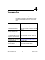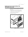
1
PXI
™
PXI-1020
User Manual
PXI-1020 User Manual
October 1999 Edition
Part Number 322612A-01
Worldwide Technical Support and Product Information
www.ni.com
National Instruments Corporate Headquarters
11500 North Mopac Expressway
Austin, Texas 78759-3504
USA Tel: 512 794 0100
Worldwide Offices
Australia 03 9879 5166, Austria 0662 45 79 90 0, Belgium 02 757 00 20, Brazil 011 284 5011,
Canada (Calgary) 403 274 9391, Canada (Ontario) 905 785 0085, Canada (Québec) 514 694 8521,
China 0755 3904939, Denmark 45 76 26 00, Finland 09 725 725 11, France 01 48 14 24 24,
Germany 089 741 31 30, Greece 30 1 42 96 427, Hong Kong 2645 3186, India 91805275406,
Israel 03 6120092, Italy 02 413091, Japan 03 5472 2970, Korea 02 596 7456, Mexico (D.F.) 5 280 7625,
Mexico (Monterrey) 8 357 7695, Netherlands 0348 433466, Norway 32 27 73 00, Poland 48 22 528 94 06,
Portugal 351 1 726 9011, Singapore 2265886, Spain 91 640 0085, Sweden 08 587 895 00,
Switzerland 056 200 51 51, Taiwan 02 2377 1200, United Kingdom 01635 523545
For further support information, see the Technical Support Resources appendix. To comment on the
documentation, send e-mail to [email protected]
© Copyright 1999 National Instruments Corporation. All rights reserved.
Important Information
Warranty
The PXI-1020 is warranted against defects in materials and workmanship for a period of one year from the date of shipment, as
evidenced by receipts or other documentation. National Instruments will, at its option, repair or replace equipment that proves to
be defective during the warranty period. This warranty includes parts and labor.
The media on which you receive National Instruments software are warranted not to fail to execute programming instructions,
due to defects in materials and workmanship, for a period of 90 days from date of shipment, as evidenced by receipts or other
documentation. National Instruments will, at its option, repair or replace software media that do not execute programming
instructions if National Instruments receives notice of such defects during the warranty period. National Instruments does not
warrant that the operation of the software shall be uninterrupted or error free.
A Return Material Authorization (RMA) number must be obtained from the factory and clearly marked on the outside of
the package before any equipment will be accepted for warranty work. National Instruments will pay the shipping costs of
returning to the owner parts which are covered by warranty.
National Instruments believes that the information in this document is accurate. The document has been carefully reviewed
for technical accuracy. In the event that technical or typographical errors exist, National Instruments reserves the right to
make changes to subsequent editions of this document without prior notice to holders of this edition. The reader should consult
National Instruments if errors are suspected. In no event shall National Instruments be liable for any damages arising out of
or related to this document or the information contained in it.
EXCEPT AS SPECIFIED HEREIN, NATIONAL INSTRUMENTS MAKES NO WARRANTIES, EXPRESS OR IMPLIED, AND SPECIFICALLY DISCLAIMS ANY
WARRANTY OF MERCHANTABILITY OR FITNESS FOR A PARTICULAR PURPOSE. CUSTOMER’S RIGHT TO RECOVER DAMAGES CAUSED BY FAULT OR
NEGLIGENCE ON THE PART OF NATIONAL INSTRUMENTS SHALL BE LIMITED TO THE AMOUNT THERETOFORE PAID BY THE CUSTOMER. NATIONAL
INSTRUMENTS WILL NOT BE LIABLE FOR DAMAGES RESULTING FROM LOSS OF DATA, PROFITS, USE OF PRODUCTS, OR INCIDENTAL OR
CONSEQUENTIAL DAMAGES, EVEN IF ADVISED OF THE POSSIBILITY THEREOF. This limitation of the liability of National Instruments will
apply regardless of the form of action, whether in contract or tort, including negligence. Any action against National Instruments
must be brought within one year after the cause of action accrues. National Instruments shall not be liable for any delay in
performance due to causes beyond its reasonable control. The warranty provided herein does not cover damages, defects,
malfunctions, or service failures caused by owner’s failure to follow the National Instruments installation, operation, or
maintenance instructions; owner’s modification of the product; owner’s abuse, misuse, or negligent acts; and power failure or
surges, fire, flood, accident, actions of third parties, or other events outside reasonable control.
Copyright
Under the copyright laws, this publication may not be reproduced or transmitted in any form, electronic or mechanical, including
photocopying, recording, storing in an information retrieval system, or translating, in whole or in part, without the prior written
consent of National Instruments Corporation.
Trademarks
National Instruments™, ni.com™, and PXI™ are trademarks of National Instruments Corporation.
Product and company names mentioned herein are trademarks or trade names of their respective companies.
WARNING REGARDING USE OF NATIONAL INSTRUMENTS PRODUCTS
(1) NATIONAL INSTRUMENTS PRODUCTS ARE NOT DESIGNED WITH COMPONENTS AND TESTING FOR A LEVEL
OF RELIABILITY SUITABLE FOR USE IN OR IN CONNECTION WITH SURGICAL IMPLANTS OR AS CRITICAL
COMPONENTS IN ANY LIFE SUPPORT SYSTEMS WHOSE FAILURE TO PERFORM CAN REASONABLY BE
EXPECTED TO CAUSE SIGNIFICANT INJURY TO A HUMAN.
(2) IN ANY APPLICATION, INCLUDING THE ABOVE, RELIABILITY OF OPERATION OF THE SOFTWARE PRODUCTS
CAN BE IMPAIRED BY ADVERSE FACTORS, INCLUDING BUT NOT LIMITED TO FLUCTUATIONS IN ELECTRICAL
POWER SUPPLY, COMPUTER HARDWARE MALFUNCTIONS, COMPUTER OPERATING SYSTEM SOFTWARE
FITNESS, FITNESS OF COMPILERS AND DEVELOPMENT SOFTWARE USED TO DEVELOP AN APPLICATION,
INSTALLATION ERRORS, SOFTWARE AND HARDWARE COMPATIBILITY PROBLEMS, MALFUNCTIONS OR
FAILURES OF ELECTRONIC MONITORING OR CONTROL DEVICES, TRANSIENT FAILURES OF ELECTRONIC
SYSTEMS (HARDWARE AND/OR SOFTWARE), UNANTICIPATED USES OR MISUSES, OR ERRORS ON THE PART OF
THE USER OR APPLICATIONS DESIGNER (ADVERSE FACTORS SUCH AS THESE ARE HEREAFTER
COLLECTIVELY TERMED “SYSTEM FAILURES”). ANY APPLICATION WHERE A SYSTEM FAILURE WOULD
CREATE A RISK OF HARM TO PROPERTY OR PERSONS (INCLUDING THE RISK OF BODILY INJURY AND DEATH)
SHOULD NOT BE RELIANT SOLELY UPON ONE FORM OF ELECTRONIC SYSTEM DUE TO THE RISK OF SYSTEM
FAILURE. TO AVOID DAMAGE, INJURY, OR DEATH, THE USER OR APPLICATION DESIGNER MUST TAKE
REASONABLY PRUDENT STEPS TO PROTECT AGAINST SYSTEM FAILURES, INCLUDING BUT NOT LIMITED TO
BACK-UP OR SHUT DOWN MECHANISMS. BECAUSE EACH END-USER SYSTEM IS CUSTOMIZED AND DIFFERS
FROM NATIONAL INSTRUMENTS' TESTING PLATFORMS AND BECAUSE A USER OR APPLICATION DESIGNER
MAY USE NATIONAL INSTRUMENTS PRODUCTS IN COMBINATION WITH OTHER PRODUCTS IN A MANNER NOT
EVALUATED OR CONTEMPLATED BY NATIONAL INSTRUMENTS, THE USER OR APPLICATION DESIGNER IS
ULTIMATELY RESPONSIBLE FOR VERIFYING AND VALIDATING THE SUITABILITY OF NATIONAL
INSTRUMENTS PRODUCTS WHENEVER NATIONAL INSTRUMENTS PRODUCTS ARE INCORPORATED IN A
SYSTEM OR APPLICATION, INCLUDING, WITHOUT LIMITATION, THE APPROPRIATE DESIGN, PROCESS AND
SAFETY LEVEL OF SUCH SYSTEM OR APPLICATION.
Compliance
FCC/Canada Radio Frequency Interference Compliance*
Determining FCC Class
The Federal Communications Commission (FCC) has rules to protect wireless communications from interference.
The FCC places digital electronics into two classes. These classes are known as Class A (for use in industrialcommercial locations only) or Class B (for use in residential or commercial locations). Depending on where it is
operated, this product could be subject to restrictions in the FCC rules. (In Canada, the Department of
Communications (DOC), of Industry Canada, regulates wireless interference in much the same way.)
Digital electronics emit weak signals during normal operation that can affect radio, television, or other wireless
products. By examining the product you purchased, you can determine the FCC Class and therefore which of the two
FCC/DOC Warnings apply in the following sections. (Some products may not be labelled at all for FCC, if so the
reader should then assume these are Class A devices.)
FCC Class A products only display a simple warning statement of one paragraph in length regarding interference and
undesired operation. Most of our products are FCC Class A. The FCC rules have restrictions regarding the locations
where FCC Class A products can be operated.
FCC Class B products display either a FCC ID code, starting with the letters EXN,
or the FCC Class B compliance mark that appears as shown here on the right.
The curious reader can consult the FCC web site http://www.fcc.gov for more
information.
FCC/DOC Warnings
This equipment generates and uses radio frequency energy and, if not installed and used in strict accordance with the
instructions in this manual and the CE Mark Declaration of Conformity**, may cause interference to radio and
television reception. Classification requirements are the same for the Federal Communications Commission (FCC)
and the Canadian Department of Communications (DOC).
Changes or modifications not expressly approved by National Instruments could void the user’s authority to operate
the equipment under the FCC Rules.
Class A
Federal Communications Commission
This equipment has been tested and found to comply with the limits for a Class A digital device, pursuant to part 15
of the FCC Rules. These limits are designed to provide reasonable protection against harmful interference when the
equipment is operated in a commercial environment. This equipment generates, uses, and can radiate radio frequency
energy and, if not installed and used in accordance with the instruction manual, may cause harmful interference to
radio communications. Operation of this equipment in a residential area is likely to cause harmful interference in
which case the user will be required to correct the interference at his own expense.
Canadian Department of Communications
This Class A digital apparatus meets all requirements of the Canadian Interference-Causing Equipment Regulations.
Cet appareil numérique de la classe A respecte toutes les exigences du Règlement sur le matériel brouilleur du
Canada.
Class B
Federal Communications Commission
This equipment has been tested and found to comply with the limits for a Class B digital device, pursuant to part 15
of the FCC Rules. These limits are designed to provide reasonable protection against harmful interference in a
residential installation. This equipment generates, uses and can radiate radio frequency energy and, if not installed
and used in accordance with the instructions, may cause harmful interference to radio communications. However,
there is no guarantee that interference will not occur in a particular installation. If this equipment does cause harmful
interference to radio or television reception, which can be determined by turning the equipment off and on, the user
is encouraged to try to correct the interference by one or more of the following measures:
• Reorient or relocate the receiving antenna.
• Increase the separation between the equipment and receiver.
• Connect the equipment into an outlet on a circuit different from that to which the receiver is connected.
• Consult the dealer or an experienced radio/TV technician for help.
Canadian Department of Communications
This Class B digital apparatus meets all requirements of the Canadian Interference-Causing Equipment Regulations.
Cet appareil numérique de la classe B respecte toutes les exigences du Règlement sur le matériel brouilleur du
Canada.
European Union - Compliance to EEC Directives
Readers in the EU/EEC/EEA must refer to the Manufacturer's Declaration of Conformity (DoC) for information**
pertaining to the CE Mark compliance scheme. The Manufacturer includes a DoC for most every hardware product
except for those bought for OEMs, if also available from an original manufacturer that also markets in the EU, or
where compliance is not required as for electrically benign apparatus or cables.
* Certain exemptions may apply in the USA, see FCC Rules §15.103 Exempted devices, and §15.105(c). Also
available in sections of CFR 47.
** The CE Mark Declaration of Conformity will contain important supplementary information and instructions for
the user or installer.
For Your Safety
Before undertaking any troubleshooting, maintenance, or exploratory procedure,
read carefully the following WARNING and CAUTION notices.
Caution
This equipment contains voltage hazardous to human life and safety, and is
capable of inflicting personal injury.
•
Chassis Grounding—The PXI-1020 chassis requires a connection
from the premise wire safety ground to the PXI-1020 chassis ground.
The earth safety ground must be connected during use of this
equipment to minimize shock hazards. Refer to the Connecting Safety
Ground section of Chapter 2, Installation, Configuration,
and Operation, for instructions on connecting safety ground.
•
Live Circuits—Operating personnel and service personnel must not
remove protective covers when operating the PXI-1020. Adjustments
and service to internal components must be undertaken by qualified
service technicians. During service of this product, the mains
connector to the premise wiring must be disconnected. Dangerous
voltages may be present under certain conditions; use extreme caution.
•
Explosive Atmosphere—Do not operate the chassis in conditions
where flammable gases are present. Under such conditions this
equipment is unsafe and may ignite the gases or gas fumes.
•
Part Replacement—Service this equipment only with parts that are
exact replacements, both electrically and mechanically. Contact
National Instruments for replacement part information. Installation of
parts with those that are not direct replacements may cause harm to
personnel operating the chassis. Furthermore, damage or fire may
occur if replacement parts are unsuitable.
•
Modification—Do not modify any part of the chassis from its original
condition. Unsuitable modifications may result in safety hazards.
Contents
About This Manual
Conventions ...................................................................................................................xi
Related Documentation..................................................................................................xi
Chapter 1
Getting Started
Unpacking ......................................................................................................................1-1
What You Need to Get Started ......................................................................................1-1
Optional Equipment .......................................................................................................1-2
Battery Pack and Cable for DC-Capable PXI-1020 ........................................1-2
Rack-Mount Kit...............................................................................................1-2
Key Features ..................................................................................................................1-2
PXI-1020 Backplane Overview .....................................................................................1-5
Interoperability with CompactPCI ..................................................................1-5
System Controller Slot ....................................................................................1-5
Star Trigger Slot ..............................................................................................1-5
Peripheral Slots................................................................................................1-5
Local Bus.........................................................................................................1-6
Trigger Bus......................................................................................................1-7
System Reference Clock..................................................................................1-7
Chapter 2
Installation, Configuration, and Operation
Site Considerations ........................................................................................................2-1
Rack Mounting ..............................................................................................................2-2
Setting Fan Speed ..........................................................................................................2-2
Connecting Safety Ground.............................................................................................2-2
Connecting to Power Source..........................................................................................2-3
DC Input Connector (DC-Capable Chassis Only) .........................................................2-3
Installing the Battery Pack (DC-Capable Power Supply Only).....................................2-4
Charging the Battery Pack (DC-Capable Power Supply Only) .....................................2-7
Power Supply Status Indication (DC-Capable Power Supply Only).............................2-8
Input Voltage Priority (DC-Capable Power Supply Only) ............................................2-8
Testing Power Up ..........................................................................................................2-8
Remote Power Monitoring and Inhibiting Interface......................................................2-9
Installing PXI Modules ..................................................................................................2-10
Installing Filler Panels ...................................................................................................2-12
Using the Chassis Initialization File ..............................................................................2-12
© National Instruments Corporation
vii
PXI-1020 User Manual
Contents
Chapter 3
Maintenance
Service Interval.............................................................................................................. 3-1
Preparation..................................................................................................................... 3-1
Cleaning......................................................................................................................... 3-1
Interior Cleaning ............................................................................................. 3-2
Exterior Cleaning ............................................................................................ 3-2
Cleaning the Fan Filters................................................................................................. 3-2
Chapter 4
Troubleshooting
Resetting the AC Mains Circuit Breaker....................................................................... 4-2
Replacing the Fuse for Optional Battery Pack (DC-Capable Chassis Only) ................ 4-3
Appendix A
Specifications
Appendix B
Pinouts
Appendix C
Technical Support Resources
Glossary
Index
Figures
Figure 1-1.
Figure 1-2.
Figure 1-3.
Figure 1-4.
Front View of the PXI-1020 Chassis .................................................... 1-3
Rear View of the AC-Only PXI-1020 Chassis ..................................... 1-4
Rear View of the DC-Capable PXI-1020 Chassis ................................ 1-4
PXI Local Bus and Star Trigger Routing.............................................. 1-6
Figure 2-1.
Figure 2-2.
Figure 2-3.
Figure 2-4.
Figure 2-5.
PXI-1020 Chassis Airflow Side View .................................................. 2-2
DC Connector on Rear of DC-Capable PXI-1020 Chassis .................. 2-4
Fan Connector ....................................................................................... 2-5
Rear of Chassis with Rear Panel and Power Supply Removed ............ 2-6
Positioning, Securing, and Connecting the Battery Pack ..................... 2-7
PXI-1020 User Manual
viii
www.ni.com
Contents
Figure 2-6.
Figure 2-7.
Installing PXI or CompactPCI Modules ...............................................2-11
Injector/Ejector Handle Position During Module Insertion ..................2-11
Figure 4-1.
Figure 4-2.
Figure 4-3.
Fan Connector .......................................................................................4-3
Rear of Chassis with Rear Panel and Power Supply Removed.............4-4
Optional Battery Pack ...........................................................................4-4
Figure A-1.
Figure A-2.
Figure A-3.
PXI-1020 Front Dimensions .................................................................A-6
PXI-1020 Top Dimensions....................................................................A-6
PXI-1020 Side Dimensions ...................................................................A-7
Tables
Table 2-1.
Table 2-2.
Table 2-3.
Power Supply Status Indication, DC Only............................................2-8
Power Supply Voltages at Power Monitoring Connector (DB-9).........2-9
DB-9 Connector Pinout ........................................................................2-9
Table 4-1.
Troubleshooting.....................................................................................4-1
Table B-1.
Table B-2.
Table B-3.
Table B-4.
Table B-5.
Table B-6.
P1 (J1) Connector Pinout for the System Controller Slot .....................B-2
P2 (J2) Connector Pinout for the System Controller Slot .....................B-3
P1 (J1) Connector Pinout for the Star Trigger Slot ...............................B-4
P2 (J2) Connector Pinout for the Star Trigger Slot ...............................B-5
P1 (J1) Connector Pinout for the Peripheral Slot ..................................B-6
P2 (J2) Connector Pinout for the Peripheral Slot ..................................B-7
© National Instruments Corporation
ix
PXI-1020 User Manual
About This Manual
The PXI-1020 User Manual describes the features of the PXI-1020 chassis
and contains information about configuration, installing the modules, and
operating the PXI-1020.
Conventions
The following conventions appear in this manual:
This icon denotes a note, which alerts you to important information.
This icon denotes a caution, which advises you of precautions to take to
avoid injury, data loss, or a system crash.
This icon denotes a warning, which advises you of precautions to take to
avoid being electrically shocked.
italic
Italic text denotes variables, emphasis, a cross reference, or an introduction
to a key concept. This font also denotes text that is a placeholder for a word
or value that you must supply.
monospace
Text in this font denotes text or characters that you should enter from the
keyboard, sections of code, programming examples, and syntax examples.
This font is also used for the proper names of disk drives, paths, directories,
programs, subprograms, subroutines, device names, functions, operations,
variables, filenames and extensions, and code excerpts.
Related Documentation
The following documents contain information that you may find helpful as
you read this manual:
•
CompactPCI Specification PICMG 2.0 R2.1
•
PXI Specification Revision 1.0
•
IEEE 1101.1-1991, IEEE Standard for Mechanical Core
Specifications for Microcomputers Using IEC 603-2 Connectors
•
IEEE 1101.10 and P1101.11, IEEE Standard for Additional
Mechanical Specifications for Microcomputers Using IEEE 1101.1
Equipment Practice
© National Instruments Corporation
xi
PXI-1020 User Manual
1
Getting Started
This chapter describes the key features of the PXI-1020 chassis, lists the
contents of your kit, and lists optional equipment you can order from
National Instruments.
Unpacking
Carefully inspect the shipping container and the chassis for damage. Check
for visible damage to the metal work. Check to make sure all handles,
hardware, and switches are undamaged. Inspect the inner chassis for any
possible damage, debris, or detached components. If damage appears to
have been caused in shipment, file a claim with the carrier. Retain the
packing material for possible inspection and/or reshipment.
What You Need to Get Started
The PXI-1020 kit contains the following items:
❑ PXI-1020 chassis
❑ Filler panels
❑ PXI-1020 User Manual
❑ Floppy disk with Chassis Initialization file, chassis.ini
Other required equipment includes:
❑ AC power cord (contact National Instruments to order your
power cord)
Note AC mains power supply cords used with the PXI-1020 must meet the requirements
of ANSI/UL817 for use in the United States, CSA C22.2 21 and 49 for use in Canada, and
IEC 227 or 245 for use in the European Union. AC mains power supply cords used with
the PXI-1020 in other countries must be approved by the authority having jurisdiction in
that country.
© National Instruments Corporation
1-1
PXI-1020 User Manual
Chapter 1
Getting Started
Optional Equipment
Contact National Instruments to order the following options for your
PXI-1020 chassis.
Battery Pack and Cable for DC-Capable PXI-1020
A DC input capable power supply is optionally installed in your PXI-1020
chassis at the factory. The DC-capable supply can be powered with
AC input or 10 to 32 VDC input and has 150 W of output.
If you have purchased a PXI-1020 with the DC-capable power supply, you
can install an optional 1.7 Ah NiCd battery pack. The chassis can draw
power from this battery pack and operate when no AC or DC input are
present or if the DC input drops below 10 V. The battery can power the
PXI-1020 for up to 12 minutes under full load.
A DC input cable is available for the PXI-1020 with the DC-capable power
supply. This cable contains an inline fuse and has unterminated ends
allowing the user to install connectors for their specific DC source.
Rack-Mount Kit
An optional rack-mount kit is available from National Instruments. This kit
allows you to install the PXI-1020 chassis into a standard 19 in. (48 cm)
wide instrument cabinet.
Key Features
The PXI -1020 is a flexible instrument platform that features an integrated
LCD display, pointing device, and CD-ROM drive that are used through
built-in interconnections on a PXI controller (PXI-8150B Series or later) as
well as eight PXI slots. An external mouse and Super VGA display can also
be connected on the controller front panel. Also, any standard keyboard can
be used with the PXI-1020 system. The PXI backplane in the PXI-1020
fully implements all timing and triggering extensions defined in the PXI
specification for high-performance instrumentation applications.
The key features of the PXI-1020 include:
PXI-1020 User Manual
•
PXI and CompactPCI (PICMG 2.0 R 2.1) module compatibility
•
Compact, 8-slot chassis for portable applications
•
300 W of usable power; 150 W for DC-capable supply
1-2
www.ni.com
Chapter 1
Getting Started
•
Universal AC input: auto-voltage and auto-frequency ranging
•
Carrying handle
•
Tilt feet
•
Rear handles double as a cable wrap
•
Built-in CD ROM drive
•
6.4 in. 640 × 480 VGA LCD color display
•
Pointing device and mouse buttons
•
Temperature sensing module controls fan speed to maintain proper
cooling
Figures 1-1, 1-2, and 1-3 show some of the key features and components
of the PXI-1020 chassis. Figure 1-1 shows the front view of the PXI-1020.
Figure 1-2 shows the rear view of the AC-only chassis, and Figure 1-3
shows the rear view of the DC-capable chassis.
1
11
2
3
1
2
3
Video Display
CD-ROM
Removable Feet (Front Feet
Swivel)
4
5
4
5
6
7
6
7
8
Pointing Device
Left Mouse Button
Right Mouse Button
Controller Expansion Slots
9
10
8
9
10
11
System Controller Slot
Star Trigger/Peripheral Slot
Peripheral Slots
Power Switch
Figure 1-1. Front View of the PXI-1020 Chassis
© National Instruments Corporation
1-3
PXI-1020 User Manual
Chapter 1
Getting Started
1
2
5
1
2
Universal AC Input
Fan Speed Selector
3
4
3
4
Circuit Breaker
5
Remote Inhibit and Power Status
Connector
Chassis Ground Screw
Figure 1-2. Rear View of the AC-Only PXI-1020 Chassis
1
2
3
4
7
1
2
3
Universal AC Input
Fan Speed Selector
Circuit Breaker
4
5
6
5
DC Input Connector
Remote Inhibit and Power Status
Connector
6
7
Power Supply Status LED
Chassis Ground Screw
Figure 1-3. Rear View of the DC-Capable PXI-1020 Chassis
PXI-1020 User Manual
1-4
www.ni.com
Chapter 1
Getting Started
PXI-1020 Backplane Overview
Interoperability with CompactPCI
The PXI-1020 backplane is interoperable with PXI-compatible products
and standard CompactPCI products. This is an important feature, as many
PXI-compatible systems may not require components that do not
implement PXI-specific features. For example, you may want to use a
standard CompactPCI network interface card in a PXI chassis.
The signals on the P1 connector of the backplane meet the requirements of
the CompactPCI specification for both the peripheral and system modules.
The PXI-specific signals are located on P2 and are found only on the
signals that are reserved or not used in the CompactPCI 64-bit
specification. Therefore, all modules that meet the requirements of the
CompactPCI 64-bit specification will function in the PXI-1020.
System Controller Slot
The System Controller slot is located in Slot 1 of the chassis as defined by
the PXI specification. It has three controller expansion slots, which are
used for system controller modules that are wider than one slot. As defined
in the PXI specification, these slots allow the controller to expand to the left
to prevent the controller from using up peripheral slots.
Star Trigger Slot
The Star Trigger (ST) slot is located at Slot 2. This slot has a dedicated
trigger line between each peripheral slot (see Figure 1-4). This slot is
intended for modules with ST functionality that can provide individual
triggers to all other peripherals. Additionally, you can use the ST slot as a
high-precision 10 MHz clock source. However, if you do not require
advanced trigger functionality, you can install any standard peripheral
module into this slot.
Peripheral Slots
There are seven peripheral slots including the ST slot.
© National Instruments Corporation
1-5
PXI-1020 User Manual
Chapter 1
Getting Started
Local Bus
The PXI backplane’s local bus is a daisy-chained bus that connects each
peripheral slot with its adjacent peripheral slots to the left and right, as
shown in Figure 1-4.
For example, a given peripheral slot’s right local bus connects to the
adjacent slot’s left local bus, and so on. Each local bus is 13 lines wide and
can pass analog signals between cards or provide a high-speed side-band
communication path that does not affect the PCI bandwidth.
Local bus signals may range from high-speed TTL signals to analog signals
as high as 42 V. Initialization software keys adjacent boards to prohibit the
use of incompatible boards. This software uses the configuration
information specific to each peripheral board to evaluate compatibility.
This method is a flexible way to define local bus functionality that is not
limited by hardware keying.
Local
Bus
Peripheral Slot [8]
Peripheral Slot [7]
Local
Bus
Peripheral Slot [4]
Local
Bus
Peripheral Slot [3]
Star Trigger/Peripheral Slot [2]
System Controller Slot [1]
Star Triggers
PCI Arbitration and Clock Signals
Figure 1-4. PXI Local Bus and Star Trigger Routing
PXI-1020 User Manual
1-6
www.ni.com
Chapter 1
Getting Started
Trigger Bus
The eight PXI trigger lines are bused to each slot. You can use the trigger
lines in a variety of ways. For example, you can use triggers to synchronize
the operation of several different PXI peripheral modules. In other
applications, one module can control carefully timed sequences of
operations performed on other modules in the system. Modules can pass
triggers to one another, allowing precisely timed responses to
asynchronous external events the system is monitoring or controlling.
System Reference Clock
The PXI-1020 supplies the PXI 10 MHz system clock signal (PXI_CLK10)
independently to each peripheral slot. An independent buffer (having a
source impedance matched to the backplane and a skew of less than 1 ns
between slots) drives the clock signal to each peripheral slot. You can use
this common reference clock signal to synchronize multiple modules in a
measurement or control system. You can drive PXI_CLK10 from an
external source through the PXI_CLK10_IN pin on the P2 connector of the
Star Trigger Slot. (See Table B-4, P2 (J2) Connector Pinout for the Star
Trigger Slot, in Appendix B, Pinouts.) Sourcing an external clock on this
pin automatically disables the backplane’s 10 MHz source.
© National Instruments Corporation
1-7
PXI-1020 User Manual
Installation, Configuration,
and Operation
2
This chapter describes how to prepare and operate your PXI-1020 chassis.
Before connecting the chassis to a power source, read this chapter and the
For Your Safety section located at the beginning of this manual.
Site Considerations
The PXI-1020 is designed to operate on a bench or in an instrument rack.
Determine how you want to use your PXI-1020 and follow the appropriate
installation instructions.
To facilitate power supply and module cooling, air enters through filters
and fan inlets located in the rear of the chassis and exits through the upper
section on the left and right sides of the chassis, as shown in Figure 2-1.
Place your PXI-1020 on a bench top or in an instrument rack so that the fans
(air inlets) and the air outlet apertures along the left and right sides of the
chassis have adequate ventilation. Keep other equipment a minimum of
3.0 in. (76.2 mm) away from the air inlets and outlets.
© National Instruments Corporation
2-1
PXI-1020 User Manual
Chapter 2
Installation, Configuration, and Operation
1
2
1
Module Cooling Air Outlets
2
Module Cooling Air Intake
Figure 2-1. PXI-1020 Chassis Airflow Side View
Rack Mounting
Rack-mount applications require the optional rack-mount kit available
from National Instruments. Refer to the instructions supplied with the
rack-mount kit to install your PXI-1020 in an instrument rack.
Setting Fan Speed
The fan speed selector switch is on the rear panel of the PXI-1020. Refer to
Figure 1-2, Rear View of the AC-Only PXI-1020 Chassis, or Figure 1-3,
Rear View of the DC-Capable PXI-1020 Chassis, for the location of the fan
speed selector switch. Select HIGH for maximum cooling or AUTO to
employ the temperature sensing module that controls the fan speed.
Connecting Safety Ground
The PXI-1020 chassis is designed with a three-position NEMA 15-5 style plug
that connects the ground line to the chassis ground. To minimize shock hazard, make sure
your electrical power outlet has an appropriate earth safety ground that is connected
whenever you power up the chassis.
Warning
PXI-1020 User Manual
2-2
www.ni.com
Chapter 2
Installation, Configuration, and Operation
If your power outlet does not have an appropriate ground connection, you
must connect the premise wire safety ground to the chassis grounding
screw located on the rear panel. Refer to Figure 1-2, Rear View of the
AC-Only PXI-1020 Chassis, or Figure 1-3, Rear View of the DC-Capable
PXI-1020 Chassis, for the location of the chassis grounding screw. To
connect the safety ground, complete the following steps:
1.
Connect a 16 AWG (1.3 mm) wire to the chassis grounding screw
using a toothed grounding lug. The wire must have green insulation
with a yellow stripe or must be noninsulated (bare).
2.
Attach the opposite end of the wire to permanent earth ground using
toothed washers or a toothed lug.
Connecting to Power Source
Caution
Do not install modules prior to performing the first power-on test.
If your PXI-1020 has an AC-only input power supply, attach input power
through the rear AC inlet using the appropriate line cord supplied. Refer to
Figure 1-2, Rear View of the AC-Only PXI-1020 Chassis, for a diagram of
the IEC 320 inlet.
If your PXI-1020 has a DC-capable power supply, you can attach an
AC line cord or a DC cord if a DC power source is available.
The power switch allows you to turn on the chassis or place it in standby
mode. Push the power switch to the On position (if not already on). Observe
that all fans become operational.
DC Input Connector (DC-Capable Chassis Only)
Figure 2-2 shows the DC input connector (P1) on the rear panel of the
DC-capable PXI-1020.
If you want to build a custom DC cable, be sure to note the positive (+) and
negative (–) terminals shown in Figure 2-2. Use the following components
or their equivalents to mate to the P1 port:
•
Positronic connector, part number CBD7W2F20000
•
Norcomp hood, part number 972-015-010-011
•
Two Positronic contacts, part number FS4008D
Install a 20 A inline fuse on the positive (+) wire of the custom cable.
© National Instruments Corporation
2-3
PXI-1020 User Manual
Chapter 2
Installation, Configuration, and Operation
Note You can purchase an optional DC cable from National Instruments that incorporates
an inline fuse and the mating connector for the P1 port.
Figure 2-2 details the P1 connector on the chassis, not the cable.
Positive
(+)
Negative
(–)
P1
Figure 2-2. DC Connector on Rear of DC-Capable PXI-1020 Chassis
Installing the Battery Pack (DC-Capable Power
Supply Only)
If you purchased a DC-capable PXI-1020 and an optional 1.7 Ah NiCd
battery pack, install it according to the following steps. (Refer to
Figures 2-3, 2-4, and 2-5.)
PXI-1020 User Manual
1.
Make sure the power switch is in the Off/Standby position.
2.
Disconnect AC power cord (and DC power cable, if attached).
3.
Remove the four screws on the rear of the chassis.
4.
Pull the rear panel away from the chassis.
2-4
www.ni.com
Chapter 2
5.
Installation, Configuration, and Operation
Disconnect the fan connector.
Figure 2-3. Fan Connector
© National Instruments Corporation
2-5
PXI-1020 User Manual
Chapter 2
Installation, Configuration, and Operation
6.
Remove the power supply by removing the two screws and sliding out
the power supply tray.
Figure 2-4. Rear of Chassis with Rear Panel and Power Supply Removed
PXI-1020 User Manual
2-6
www.ni.com
Chapter 2
7.
Installation, Configuration, and Operation
Secure the battery pack inside the chassis using the four screws
supplied with the battery pack.
1
1
Battery Pack Connector Mates
Figure 2-5. Positioning, Securing, and Connecting the Battery Pack
8.
Connect the two plugs from the battery pack to the mating connectors
on the power supply, as shown in Figure 2-5.
9.
Reinstall the power supply tray and replace the two screws.
10. Reconnect the fan connector and rear panel.
11. Replace the four screws.
12. Reconnect the AC power cord (and DC power cable, if previously
attached).
Charging the Battery Pack (DC-Capable Power
Supply Only)
The optional battery pack is charged when either the AC power or the
external DC power is connected, regardless of the power switch position.
The power supply has circuitry to prevent the battery pack from
overcharging.
© National Instruments Corporation
2-7
PXI-1020 User Manual
Chapter 2
Installation, Configuration, and Operation
Power Supply Status Indication (DC-Capable Power
Supply Only)
If your PXI-1020 has a DC-capable power supply, refer to the following
table for power supply indications provided by the Power Supply Status
LED. Refer to Figure 1-3, Rear View of the DC-Capable PXI-1020
Chassis, for the location of the Power Supply Status LED.
.
Table 2-1. Power Supply Status Indication, DC Only
Power Source
Power Switch Mode
Status LED
AC or External DC Input
Standby
Green
AC or External DC Input
On
Bright Green
Optional Battery Pack
On
Yellow
Optional Battery Pack
(Discharged)
On
Red
Input Voltage Priority (DC-Capable Power Supply Only)
If more than one power source is connected at the same time, the priority
of the power sources is as follows.
1.
AC Input
2.
DC Input
3.
Internal Battery Pack
Testing Power Up
When connecting digital voltmeter probes to the rear D-sub connector, be careful
not to short the probe leads together. Doing so could damage the power supply.
Caution
You can use a digital voltmeter to ensure all voltage levels in your
PXI-1020 are within the allowable limits. Referring to Table 2-2, connect
one lead of the voltmeter to a supply pin on the remote power monitoring
connector (9-pin D-sub) located on the rear panel. Refer to Table 2-3 for a
pinout diagram of the remote power monitoring connector. Connect the
reference lead of the voltmeter to one of the ground pins. Compare each
voltage reading to the values listed in Table 2-2.
PXI-1020 User Manual
2-8
www.ni.com
Chapter 2
Installation, Configuration, and Operation
Note Use the rear-panel D-sub connector to check voltages only. Do not use the connector
to supply power to external devices.
Table 2-2. Power Supply Voltages at Power Monitoring Connector (DB-9)
Pin
Supply
Acceptable Voltage Range
2
+5 V
4.75 to 5.25 V
4
+3.3 V
3.135 to 3.465 V
6
+12 V
11.4 to 12.6 V
8
–12 V
–12.6 to –11.4 V
1, 9
Logic Ground
N/A
If the voltages fall within the specified ranges, the mainframe complies
with the CompactPCI voltage limit specifications. Notice that the
rear-panel D-sub connector is to be used to check voltages only. Do not
use these voltages to supply power to external devices.
Note If the fans or power unit fail to function properly, refer to Chapter 4,
Troubleshooting.
Remote Power Monitoring and Inhibiting Interface
The PXI-1020 mainframe supports remote power monitoring and
inhibiting via a 9-pin D-sub connector located on the rear panel. Table 2-3
shows the pinout of the DB-9 connector.
Table 2-3. DB-9 Connector Pinout
DB-9 Pin
© National Instruments Corporation
Signal
1
Logic Ground
2
+5 V
3
Inhibit Return (DC-capable supply only)
4
+3.3 V
5
Inhibit*
6
+12 V
2-9
PXI-1020 User Manual
Chapter 2
Installation, Configuration, and Operation
Table 2-3. DB-9 Connector Pinout (Continued)
DB-9 Pin
Signal
7
Reserved
8
–12 V
9
Logic Ground
5
4
9
3
8
2
7
1
6
You can use the Inhibit signal (active low) to turn off the power supply
outputs. To use this feature, connect the Inhibit pin (pin 5) to a Logic
Ground pin (pin 1 or 9) on the AC-only input power supply or Inhibit
Return (pin 3) for the DC-capable power supply. Make sure the front
(standby) switch is in the ON position. As long as the connection is made,
the power supply inhibits its DC outputs. DC output resumes when Inhibit
is no longer connected. For remote reset, connect a momentary switch
between pin 5 and pin 1 (or pin 9) on the AC-only input power supply or
between pin 5 and pin 3 for the DC-capable power supply.
Installing PXI Modules
Caution
Turn off the chassis power before installing CompactPCI or PXI modules.
Install a module into a chassis slot by first placing the module’s card edges
into the front module guides (top and bottom), as shown in Figure 2-6.
Slide the module to the rear of the chassis, making sure that the
injector/ejector handle is pushed down as shown in Figure 2-7.
When you begin to feel resistance, push up on the injector/ejector handle to
inject the card into the frame. Secure the module’s front panel to the chassis
using the module’s front-panel mounting screws.
PXI-1020 User Manual
2-10
www.ni.com
Chapter 2
Installation, Configuration, and Operation
1
2
3
5
4
1
2
PXI-1020 Chassis
PXI-8156B System Controller
3
4
PXI Board
Injector/Ejector Handle
5
Injector/Ejector Rail
Figure 2-6. Installing PXI or CompactPCI Modules
Figure 2-7. Injector/Ejector Handle Position During Module Insertion
© National Instruments Corporation
2-11
PXI-1020 User Manual
Chapter 2
Installation, Configuration, and Operation
Installing Filler Panels
To optimize module cooling performance, install filler panels into unused
or empty slots. Secure with the captive mounting screws.
Using the Chassis Initialization File
To assist system integrators, the PXI specification requires manufacturers
of PXI chassis and system modules to document the capabilities of their
products. The minimum documentation requirements are contained
in .ini files, which consist of ASCII text. The system integrator can
read the .ini file, and configuration utilities and device drivers can also
use this file. The PXI-1020 chassis initialization file, chassis.ini,
is included on the diskette for your PXI-1020.
PXI-1020 User Manual
2-12
www.ni.com
3
Maintenance
This chapter describes basic maintenance procedures you can perform on
the PXI-1020 chassis.
Service Interval
Clean the chassis fan filter at a maximum interval of six months.
Depending on the amount of use and ambient dust levels in the operating
environment, the filter may require more frequent cleaning.
Clean dust from the chassis exterior (and interior) as needed, based on the
operating environment. Periodic cleaning increases reliability.
Preparation
The information in this section is designed for use by qualified service
personnel. Read the For Your Safety section at the beginning of this manual
before attempting any procedures in this chapter.
Many components within the chassis are susceptible to static discharge damage.
Service the chassis only in a static-free environment. Observe standard handling
precautions for static-sensitive devices while servicing the chassis. Always wear a
grounded wrist strap, or equivalent, while servicing the chassis.
Caution
Cleaning
Cleaning procedures consist of exterior and interior cleaning of the chassis
and cleaning the fan filter. Refer to your module user documentation for
information on cleaning the individual CompactPCI or PXI modules.
Always power-off the chassis and disconnect the power cord before cleaning or
servicing the chassis.
Caution
© National Instruments Corporation
3-1
PXI-1020 User Manual
Chapter 3
Maintenance
Interior Cleaning
Use a dry, low-velocity stream of air to clean the interior of the chassis. Use
a soft-bristle brush for cleaning around components. If you must use a
liquid for minor interior cleaning, use a 75% isopropyl alcohol solution and
rinse with deionized water.
Exterior Cleaning
Clean the exterior surfaces of the chassis with a dry lint-free cloth or a
soft-bristle brush. If any dirt remains, wipe with a cloth moistened in a mild
soap solution. Remove any soap residue by wiping with a cloth moistened
with clear water. Do not use abrasive compounds on any part of the chassis.
Avoid getting moisture inside the chassis during exterior cleaning. Use just
enough moisture to dampen the cloth.
Caution
Do not wash the connectors or switches. Cover these components while cleaning the
chassis.
Do not use chemical cleaning agents; they may damage the chassis. Avoid chemicals that
contain benzene, toluene, xylene, acetone, or similar solvents.
Cleaning the Fan Filters
You can easily remove the fan filters from the rear of the chassis by
removing the plastic housing attached to each fan. You can then remove the
filters.
Clean the filters by washing them in a mild soap solution and then
vacuuming or blowing air through them. Rinse the filters with water and
allow them to dry before reinstalling.
PXI-1020 User Manual
3-2
www.ni.com
4
Troubleshooting
This chapter describes basic troubleshooting procedures for the PXI-1020
chassis.
Refer to Table 4-1 to troubleshoot the PXI-1020 chassis. The table lists
possible causes for power failure and recommends ways to correct the
problem.
Table 4-1. Troubleshooting
Possible Cause
What to Do
PXI-1020 chassis is not connected to
power source.
Make sure that the PXI-1020 is connected to a live
electrical outlet. Try operating another piece of
equipment from this outlet.
Power switch is not switched on.
Set the power switch to the On position. The green LED
should be lit.
Remote inhibiting input on the rear
panel of the mainframe is active.
Deactivate your system’s remote inhibiting control.
Circuit breaker is tripped.
Reset the circuit breaker. Refer to the Resetting the AC
Mains Circuit Breaker section of this chapter.
If DC-capable PXI-1020 is powered by
an external DC source, inline fuse on
DC-power cord may be blown.
Check fuse and replace, if necessary, with same type.
If DC-capable PXI-1020 is powered by
optional battery pack, inline fuse to the
battery pack may be blown.
Check fuse and replace. See the section Replacing the
Fuse for Optional Battery Pack (DC-Capable Chassis
Only) in this chapter.
If DC-capable PXI-1020 is powered by
an optional battery pack only, battery
pack may be discharged.
Connect PXI-1020 to AC or DC power source to charge
battery. (Note: The battery is charged whether the power
switch is in the On or Standby position.)
Power supply has failed.
Contact National Instruments.
© National Instruments Corporation
4-1
PXI-1020 User Manual
Chapter 4
Troubleshooting
Resetting the AC Mains Circuit Breaker
If your PXI-1020 is connected to an AC source and encounters an
over-current condition, the circuit breaker on the rear panel will trip to
prevent damage to the mainframe. Complete the following steps to reset the
circuit breaker:
1.
Make sure the power switch is in the Off/Standby position.
2.
Disconnect the AC line cord.
3.
Depress the circuit breaker to reset it.
4.
Reconnect the AC line cord.
5.
Turn the power switch to the On position.
If the circuit breaker trips again, complete the following steps:
PXI-1020 User Manual
1.
Turn the power switch to the Off/Standby position.
2.
Disconnect the mainframe from the AC mains power source.
3.
Remove all modules from the mainframe.
4.
Complete the test procedure described in the Connecting to Power
Source section in Chapter 2, Installation, Configuration,
and Operation.
5.
If any voltages are outside the acceptable limits, contact National
Instruments.
6.
If all voltages are within the acceptable limits, verify that your
PXI-1020 can meet the power requirements of your CompactPCI or
PXI modules. Overloading the chassis can cause the breaker to trip.
Refer to Appendix A, Specifications.
7.
The over-current condition that caused the circuit breaker to trip
may be due to a faulty CompactPCI or PXI module. Refer to the
documentation supplied with the modules for troubleshooting your
modules.
4-2
www.ni.com
Chapter 4
Troubleshooting
Replacing the Fuse for Optional Battery Pack
(DC-Capable Chassis Only)
The optional battery pack for the DC-capable PXI-1020 has a 10 A inline
automotive-type fuse. Complete the following steps to replace the fuse
shown in Figure 4-3.
1.
Make sure the power switch is in the Off/Standby position.
2.
Disconnect AC power cord (and DC power cable, if attached).
3.
Remove the four screws on the rear of the chassis.
4.
Pull the rear panel away from the chassis.
5.
Disconnect the fan connector.
Figure 4-1. Fan Connector
© National Instruments Corporation
4-3
PXI-1020 User Manual
Chapter 4
Troubleshooting
6.
Remove the power supply by removing the two screws and sliding out
the power supply tray.
Figure 4-2. Rear of Chassis with Rear Panel and Power Supply Removed
7.
Replace the battery pack fuse.
Fuse
Fuse Holder
Battery Pack
Figure 4-3. Optional Battery Pack
8.
Reinstall the power supply tray and replace the two screws.
9.
Reconnect the fan connector and rear panel.
10. Replace the four screws.
11. Reconnect the AC power cord (and DC power cable, if previously
attached).
PXI-1020 User Manual
4-4
www.ni.com
A
Specifications
This appendix contains specifications for the PXI-1020 chassis.
Electrical
AC Input Specifications for AC-Only Power Supply
Input voltage range................................. 90–264 VAC
Input frequency range ............................ 47 to 63 Hz
Over-current protection .......................... 10 A circuit breaker
Power disconnect ................................... The power switch causes the
power module to supply DC
power to the CompactPCI/PXI
backplane. The power cord
provides main power disconnect.
Maximum steady state operating
operating current .................................... 8 A
Line regulation ....................................... ±0.2% over operating line range
Efficiency ............................................... 70% typical
DC Output Specifications for AC-Only Power Supply
Maximum usable power ......................... 300 W
Maximum ripple and noise .................... 1% ripple, 1% noise,
20 MHz bandwidth
© National Instruments Corporation
A-1
PXI-1020 User Manual
Appendix A
Specifications
DC Current Capacity (IMP)
\
Voltage
IMP (Steady-State
Current)
Regulation
+3.3 V
35 A
< 1.5%
+5 V
25 A
< 1%
+12 V
4A
< 5%
–12 V
1A
< 5%
Power supply MTTR ..............................Replacement in under 5 minutes
AC Input Specifications for DC-Capable Power
Supply
Input voltage range .................................85–265 VAC
Input frequency range .............................45 to 65 Hz
Over-current protection...........................5 A circuit breaker
Operating current (RMS steady state) ....3.0 A
Line regulation........................................±0.2% over operating line range
Efficiency................................................85% typical
Power disconnect ....................................The power switch causes the
power module to supply DC
power to the CompactPCI/PXI
backplane. The power cord
provides main power disconnect.
DC Input Specifications for DC-Capable Power
Supply
Input voltage range .................................10–32 V
DC to DC isolation .................................500 Vrms
Over-current protection...........................Inline fuse must be installed
into DC input cable
Efficiency................................................82% typical
PXI-1020 User Manual
A-2
www.ni.com
Appendix A
Specifications
Power disconnect ................................... The power switch causes the
power module to supply DC
power to the CompactPCI/PXI
backplane. The power cord
provides main power disconnect.
DC Output Specifications for DC-Capable Power
Supply
Maximum usable power ......................... 150 W
Ripple and noise..................................... 1% ripple, 1% noise,
20 MHz bandwidth
DC Current Capacity (IMP)
Voltage
IMP (Steady-State
Current)
Regulation
+3.3 V
10 A
< 2%
+5 V
20 A (3.3 V power)
< 2%
+12 V
4A
< 2%
–12 V
0.4 A
< 5%
Power supply MTTR.............................. Replacement in under 5 minutes
Cooling
Per slot cooling capacity ........................ Slot cooling capacity in
worst-case slot is 20 W with
fan speed set to HIGH
Module cooling system .......................... Forced air circulation (positive
pressurization) via two 60 cfm
fans with AUTO/HIGH speed
selector
Slot airflow direction.............................. P1 to P2, bottom of module to
top of module
Module cooling
Intake .............................................. Rear of chassis
Exhaust............................................ Upper left and right sides
© National Instruments Corporation
A-3
PXI-1020 User Manual
Appendix A
Specifications
Safety
UL 3111-1, IEC 1010-1, CSA 22.2 No. 1010.1
Installation Category II
Pollution Degree 2
Safety Class 1
Environmental
Operating temperature ............................0 to 50 °C
Storage temperature ................................–20 to 70 °C
Operating relative humidity ....................10 to 90%, noncondensing
Functional shock (operating) ..................MIL-T-28800E CLASS 3,
30 g half-sine shock pulse
(also meets IEC 60068-2-27)
Operating location ..................................Indoor use
Random vibration
Operational ......................................5 to 500 Hz, 0.3 g RMS
Non-operational1 .............................10 to 500 Hz, 2.4 gRMS
EMC emissions.......................................FCC Class A compliant and
EN 55011 Group 1 Class A
compliant
EMC immunity .......................................Refer to DOC supplied with
chassis for compliance to
relevant directives.
1
Random vibration profiles were developed in accordance with MIL-T-28800E CLASS 3 and MIL-STD-810E Method
514 Test levels exceed those recommended in MIL-STD-810E for Category 1 (Basic Transportation), Figures 514.4-1 through
514.4-3.
PXI-1020 User Manual
A-4
www.ni.com
Appendix A
Specifications
Backplane
Size......................................................... 3U-sized; one system slot
(with three system expansion
slots) and seven peripheral slots.
Compliant with IEEE 1101.10
mechanical packaging.
PXI Specification Revision 1.0
compliant.
Accepts both PXI and
CompactPCI (PICMG 2.0 R2.1)
3U modules.
Backplane bare-board material .............. UL 94 V-0 recognized
(File No. E 116551)
Backplane connectors ............................ Conform to IEC 917 and IEC
1076-4-101, and are UL 94 V-0
rated
Mechanical
Overall dimensions standard chassis...... 17.71 by 44.51 by 36.95 cm
(6.97 by 17.52 by 14.55 in.)
Weight .................................................... 9.75 kg (21.5 lb.)
Maximum module weight ...................... 1.82 kg (4 lb.)
© National Instruments Corporation
A-5
PXI-1020 User Manual
Appendix A
Specifications
Figures A-1, A-2, and A-3 show the PXI-1020 dimensions.
.368
[.934]
17.52
[44.51]
6.97
[17.71]
Figure A-1. PXI-1020 Front Dimensions
14.55
13.13 [36.95]
[33.34]
Figure A-2. PXI-1020 Top Dimensions
PXI-1020 User Manual
A-6
www.ni.com
Appendix A
Specifications
10.50
[26.68]
9.67
[24.57]
2.10
[5.32]
1.20
[3.06]
1.27
[3.22]
3.48
[8.85]
1.88
[4.78]
.57
[1.45]
Handle and Rack Mount Kit
Mounting Holes 4X 6-32, .20 Max.
Figure A-3. PXI-1020 Side Dimensions
© National Instruments Corporation
A-7
PXI-1020 User Manual
B
Pinouts
This appendix describes the P1 and P2 connector pinouts for the PXI-1020
backplane.
Table B-1 shows the P1 (J1) connector pinout for the System Controller
slot.
Table B-2 shows the P2 (J2) connector pinout for the System Controller
slot.
Table B-3 shows the P1 (J1) connector pinout for the Star Trigger slot.
Table B-4 shows the P2 (J2) connector pinout for the Star Trigger slot.
Table B-5 shows the P1 (J1) connector pinout for the peripheral slots.
Table B-6 shows the P2 (J2) connector pinout for the peripheral slots.
Note PXI signals are shown in bold.
© National Instruments Corporation
B-1
PXI-1020 User Manual
Appendix B
Pinouts
Table B-1. P1 (J1) Connector Pinout for the System Controller Slot
Pin
Z
A
B
C
D
E
F
25
GND
5V
REQ64#
ENUM#
3.3V
5V
GND
24
GND
AD[1]
5V
V(I/O)
AD[0]
ACK64#
GND
23
GND
3.3V
AD[4]
AD[3]
5V
AD[2]
GND
22
GND
AD[7]
GND
3.3V
AD[6]
AD[5]
GND
21
GND
3.3V
AD[9]
AD[8]
M66EN
C/BE[0]#
GND
20
GND
AD[12]
GND
V(I/O)
AD[11]
AD[10]
GND
19
GND
3.3V
AD[15]
AD[14]
GND
AD[13]
GND
18
GND
SERR#
GND
3.3V
PAR
C/BE[1]#
GND
17
GND
3.3V
SDONE
SBO#
GND
PERR#
GND
16
GND
DEVSEL#
GND
V(I/O)
STOP#
LOCK#
GND
15
GND
3.3V
FRAME#
IRDY#
GND
TRDY#
GND
12–14
Key Area
11
GND
AD[18]
AD[17]
AD[16]
GND
C/BE[2]#
GND
10
GND
AD[21]
GND
3.3V
AD[20]
AD[19]
GND
9
GND
C/BE[3]#
IDSEL
AD[23]
GND
AD[22]
GND
8
GND
AD[26]
GND
V(I/O)
AD[25]
AD[24]
GND
7
GND
AD[30]
AD[29]
AD[28]
GND
AD[27]
GND
6
GND
REQ#
GND
3.3V
CLK
AD[31]
GND
5
GND
BRSVP1A5
BRSVP1B5
RST#
GND
GNT#
GND
4
GND
BRSVP1A4
GND
V(I/O)
INTP
INTS
GND
3
GND
INTA#
INTB#
INTC#
5V
INTD#
GND
2
GND
TCK
5V
TMS
TDO
TDI
GND
1
GND
5V
–12V
TRST#
+12V
5V
GND
PXI-1020 User Manual
B-2
www.ni.com
Appendix B
Pinouts
Table B-2. P2 (J2) Connector Pinout for the System Controller Slot
Pin
Z
22
GND
21
A
B
C
D
E
F
PXI_RSVA22
PXI_RSVB22
PXI_RSVC22
PXI_RSVD22
PXI_RSVE22
GND
GND
RSV
GND
RSV
RSV
RSV
GND
20
GND
RSV
RSV
RSV
GND
RSV
GND
19
GND
RSV
GND
RSV
RSV
RSV
GND
18
GND
PXI_TRIG3
PXI_TRIG4
PXI_TRIG5
GND
PXI_TRIG6
GND
17
GND
PXI_TRIG2
GND
PRST#
REQ6#
GNT6#
GND
16
GND
PXI_TRIG1
PXI_TRIG0
DEG#
GND
PXI_TRIG7
GND
15
GND
PXI_BRSVA15
GND
FAL#
REQ5#
GNT5#
GND
14
GND
AD[35]
AD[34]
AD[33]
GND
AD[32]
GND
13
GND
AD[38]
GND
V(I/O)
AD[37]
AD[36]
GND
12
GND
AD[42]
AD[41]
AD[40]
GND
AD[39]
GND
11
GND
AD[45]
GND
V(I/O)
AD[44]
AD[43]
GND
10
GND
AD[49]
AD[48]
AD[47]
GND
AD[46]
GND
9
GND
AD[52]
GND
V(I/O)
AD[51]
AD[50]
GND
8
GND
AD[56]
AD[55]
AD[54]
GND
AD[53]
GND
7
GND
AD[59]
GND
V(I/O)
AD[58]
AD[57]
GND
6
GND
AD[63]
AD[62]
AD[61]
GND
AD[60]
GND
5
GND
C/BE[5]#
GND
V(I/O)
C/BE[4]#
PAR64
GND
4
GND
V(I/O)
PXI_BRSVB4
C/BE[7]#
GND
C/BE[6]#
GND
3
GND
CLK4
GND
GNT3#
REQ4#
GNT4#
GND
2
GND
CLK2
CLK3
SYSEN#
GNT2#
REQ3#
GND
1
GND
CLK1
GND
REQ1#
GNT1#
REQ2#
GND
© National Instruments Corporation
B-3
PXI-1020 User Manual
Appendix B
Pinouts
Table B-3. P1 (J1) Connector Pinout for the Star Trigger Slot
Pin
Z
A
B
C
D
E
F
25
GND
5V
REQ64#
ENUM#
3.3V
5V
GND
24
GND
AD[1]
5V
V(I/O)
AD[0]
ACK64#
GND
23
GND
3.3V
AD[4]
AD[3]
5V
AD[2]
GND
22
GND
AD[7]
GND
3.3V
AD[6]
AD[5]
GND
21
GND
3.3V
AD[9]
AD[8]
M66EN
C/BE[0]#
GND
20
GND
AD[12]
GND
V(I/O)
AD[11]
AD[10]
GND
19
GND
3.3V
AD[15]
AD[14]
GND
AD[13]
GND
18
GND
SERR#
GND
3.3V
PAR
C/BE[1]#
GND
17
GND
3.3V
SDONE
SBO#
GND
PERR#
GND
16
GND
DEVSEL#
GND
V(I/O)
STOP#
LOCK#
GND
15
GND
3.3V
FRAME#
IRDY#
GND
TRDY#
GND
12–14
Key Area
11
GND
AD[18]
AD[17]
AD[16]
GND
C/BE[2]#
GND
10
GND
AD[21]
GND
3.3V
AD[20]
AD[19]
GND
9
GND
C/BE[3]#
IDSEL
AD[23]
GND
AD[22]
GND
8
GND
AD[26]
GND
V(I/O)
AD[25]
AD[24]
GND
7
GND
AD[30]
AD[29]
AD[28]
GND
AD[27]
GND
6
GND
REQ#
GND
3.3V
CLK
AD[31]
GND
5
GND
BRSVP1A5
BRSVP1B5
RST#
GND
GNT#
GND
4
GND
BRSVP1A4
GND
V(I/O)
INTP
INTS
GND
3
GND
INTA#
INTB#
INTC#
5V
INTD#
GND
2
GND
TCK
5V
TMS
TDO
TDI
GND
1
GND
5V
–12V
TRST#
+12V
5V
GND
PXI-1020 User Manual
B-4
www.ni.com
Appendix B
Pinouts
Table B-4. P2 (J2) Connector Pinout for the Star Trigger Slot
Pin
Z
22
GND
21
A
B
C
PXI_RSVA22
PXI_RSVB22
PXI_RSVC22
GND
PXI_LBR0
GND
20
GND
PXI_LBR4
19
GND
18
E
F
PXI_RSVD22
PXI_RSVE22
GND
PXI_LBR1
PXI_LBR2
PXI_LBR3
GND
PXI_LBR5
PXI_STAR0
GND
PXI_STAR1
GND
PXI_STAR2
GND
PXI_STAR3
PXI_STAR4
PXI_STAR5
GND
GND
PXI_TRIG3
PXI_TRIG4
PXI_TRIG5
GND
PXI_TRIG6
GND
17
GND
PXI_TRIG2
GND
PRST#
PXI_CLK10_IN
PXI_CLK10
GND
16
GND
PXI_TRIG1
PXI_TRIG0
DEG#
GND
PXI_TRIG7
GND
15
GND
PXI_BRSVA15
GND
FAL#
PXI_STAR6
PXI_LBR6
GND
14
GND
AD[35]
AD[34]
AD[33]
GND
AD[32]
GND
13
GND
AD[38]
GND
V(I/O)
AD[37]
AD[36]
GND
12
GND
AD[42]
AD[41]
AD[40]
GND
AD[39]
GND
11
GND
AD[45]
GND
V(I/O)
AD[44]
AD[43]
GND
10
GND
AD[49]
AD[48]
AD[47]
GND
AD[46]
GND
9
GND
AD[52]
GND
V(I/O)
AD[51]
AD[50]
GND
8
GND
AD[56]
AD[55]
AD[54]
GND
AD[53]
GND
7
GND
AD[59]
GND
V(I/O)
AD[58]
AD[57]
GND
6
GND
AD[63]
AD[62]
AD[61]
GND
AD[60]
GND
5
GND
C/BE[5]#
GND
V(I/O)
C/BE[4]#
PAR64
GND
4
GND
V(I/O)
PXI_BRSVB4
C/BE[7]#
GND
C/BE[6]#
GND
3
GND
PXI_LBR7
GND
PXI_LBR8
PXI_LBR9
PXI_LBR10
GND
2
GND
PXI_LBR11
PXI_LBR12
SYSEN#
PXI_STAR7
PXI_STAR8
GND
1
GND
PXI_STAR9
GND
PXI_STAR10
PXI_STAR11
PXI_STAR12
GND
© National Instruments Corporation
B-5
D
PXI-1020 User Manual
Appendix B
Pinouts
Table B-5. P1 (J1) Connector Pinout for the Peripheral Slot
Pin
Z
A
B
C
D
E
F
25
GND
5V
REQ64#
ENUM#
3.3V
5V
GND
24
GND
AD[1]
5V
V(I/O)
AD[0]
ACK64#
GND
23
GND
3.3V
AD[4]
AD[3]
5V
AD[2]
GND
22
GND
AD[7]
GND
3.3V
AD[6]
AD[5]
GND
21
GND
3.3V
AD[9]
AD[8]
M66EN
C/BE[0]#
GND
20
GND
AD[12]
GND
V(I/O)
AD[11]
AD[10]
GND
19
GND
3.3V
AD[15]
AD[14]
GND
AD[13]
GND
18
GND
SERR#
GND
3.3V
PAR
C/BE[1]#
GND
17
GND
3.3V
SDONE
SBO#
GND
PERR#
GND
16
GND
DEVSEL#
GND
V(I/O)
STOP#
LOCK#
GND
15
GND
3.3V
FRAME#
IRDY#
GND
TRDY#
GND
12–14
Key Area
11
GND
AD[18]
AD[17]
AD[16]
GND
C/BE[2]#
GND
10
GND
AD[21]
GND
3.3V
AD[20]
AD[19]
GND
9
GND
C/BE[3]#
IDSEL
AD[23]
GND
AD[22]
GND
8
GND
AD[26]
GND
V(I/O)
AD[25]
AD[24]
GND
7
GND
AD[30]
AD[29]
AD[28]
GND
AD[27]
GND
6
GND
REQ#
GND
3.3V
CLK
AD[31]
GND
5
GND
BRSVP1A5
BRSVP1B5
RST#
GND
GNT#
GND
4
GND
BRSVP1A4
GND
V(I/O)
INTP
INTS
GND
3
GND
INTA#
INTB#
INTC#
5V
INTD#
GND
2
GND
TCK
5V
TMS
TDO
TDI
GND
1
GND
5V
–12V
TRST#
+12V
5V
GND
PXI-1020 User Manual
B-6
www.ni.com
Appendix B
Pinouts
Table B-6. P2 (J2) Connector Pinout for the Peripheral Slot
Pin
Z
22
GND
21
A
B
C
D
E
PXI_RSVA22
PXI_RSVB22
PXI_RSVC22
PXI_RSVD22
PXI_RSVE22
GND
GND
PXI_LBR0
GND
PXI_LBR1
PXI_LBR2
PXI_LBR3
GND
20
GND
PXI_LBR4
PXI_LBR5
PXI_LBL0
GND
PXI_LBL1
GND
19
GND
PXI_LBL2
GND
PXI_LBL3
PXI_LBL4
PXI_LBL5
GND
18
GND
PXI_TRIG3
PXI_TRIG4
PXI_TRIG5
GND
PXI_TRIG6
GND
17
GND
PXI_TRIG2
GND
PRST#
PXI_STAR
PXI_CLK10
GND
16
GND
PXI_TRIG1
PXI_TRIG0
DEG#
GND
PXI_TRIG7
GND
15
GND
PXI_BRSVA15
GND
FAL#
PXI_LBL6
PXI_LBR6
GND
14
GND
AD[35]
AD[34]
AD[33]
GND
AD[32]
GND
13
GND
AD[38]
GND
V(I/O)
AD[37]
AD[36]
GND
12
GND
AD[42]
AD[41]
AD[40]
GND
AD[39]
GND
11
GND
AD[45]
GND
V(I/O)
AD[44]
AD[43]
GND
10
GND
AD[49]
AD[48]
AD[47]
GND
AD[46]
GND
9
GND
AD[52]
GND
V(I/O)
AD[51]
AD[50]
GND
8
GND
AD[56]
AD[55]
AD[54]
GND
AD[53]
GND
7
GND
AD[59]
GND
V(I/O)
AD[58]
AD[57]
GND
6
GND
AD[63]
AD[62]
AD[61]
GND
AD[60]
GND
5
GND
C/BE[5]#
GND
V(I/O)
C/BE[4]#
PAR64
GND
4
GND
V(I/O)
PXI_BRSVB4
C/BE[7]#
GND
C/BE[6]#
GND
3
GND
PXI_LBR7
GND
PXI_LBR8
PXI_LBR9
PXI_LBR10
GND
2
GND
PXI_LBR11
PXI_LBR12
SYSEN#
PXI_LBL7
PXI_LBL8
GND
1
GND
PXI_LBL9
GND
PXI_LBL10
PXI_LBL11
PXI_LBL12
GND
© National Instruments Corporation
B-7
F
PXI-1020 User Manual
Technical Support Resources
C
This appendix describes the comprehensive resources available to you in
the Technical Support section of the National Instruments Web site and
provides technical support telephone numbers for you to use if you have
trouble connecting to our Web site or if you do not have internet access.
NI Web Support
To provide you with immediate answers and solutions 24 hours a day,
365 days a year, National Instruments maintains extensive online technical
support resources. They are available to you at no cost, are updated daily,
and can be found in the Technical Support section of our Web site at
www.ni.com/support
Online Problem-Solving and Diagnostic Resources
•
KnowledgeBase—A searchable database containing thousands of
frequently asked questions (FAQs) and their corresponding answers or
solutions, including special sections devoted to our newest products.
The database is updated daily in response to new customer experiences
and feedback.
•
Troubleshooting Wizards—Step-by-step guides lead you through
common problems and answer questions about our entire product line.
Wizards include screen shots that illustrate the steps being described
and provide detailed information ranging from simple getting started
instructions to advanced topics.
•
Product Manuals—A comprehensive, searchable library of the latest
editions of National Instruments hardware and software product
manuals.
•
Hardware Reference Database—A searchable database containing
brief hardware descriptions, mechanical drawings, and helpful images
of jumper settings and connector pinouts.
•
Application Notes—A library with more than 100 short papers
addressing specific topics such as creating and calling DLLs,
developing your own instrument driver software, and porting
applications between platforms and operating systems.
© National Instruments Corporation
C-1
PXI-1020 User Manual
Appendix C
Technical Support Resources
Software-Related Resources
•
Instrument Driver Network—A library with hundreds of instrument
drivers for control of standalone instruments via GPIB, VXI, or serial
interfaces. You also can submit a request for a particular instrument
driver if it does not already appear in the library.
•
Example Programs Database—A database with numerous,
non-shipping example programs for National Instruments
programming environments. You can use them to complement the
example programs that are already included with National Instruments
products.
•
Software Library—A library with updates and patches to application
software, links to the latest versions of driver software for National
Instruments hardware products, and utility routines.
Worldwide Support
National Instruments has offices located around the globe. Many branch
offices maintain a Web site to provide information on local services. You
can access these Web sites from www.ni.com/worldwide
If you have trouble connecting to our Web site, please contact your local
National Instruments office or the source from which you purchased your
National Instruments product(s) to obtain support.
For telephone support in the United States, dial 512 795 8248. For
telephone support outside the United States, contact your local branch
office:
Australia 03 9879 5166, Austria 0662 45 79 90 0, Belgium 02 757 00 20,
Brazil 011 284 5011, Canada (Calgary) 403 274 9391,
Canada (Ontario) 905 785 0085, Canada (Québec) 514 694 8521,
China 0755 3904939, Denmark 45 76 26 00, Finland 09 725 725 11,
France 01 48 14 24 24, Germany 089 741 31 30, Greece 30 1 42 96 427,
Hong Kong 2645 3186, India 91805275406, Israel 03 6120092,
Italy 02 413091, Japan 03 5472 2970, Korea 02 596 7456,
Mexico (D.F.) 5 280 7625, Mexico (Monterrey) 8 357 7695,
Netherlands 0348 433466, Norway 32 27 73 00, Poland 48 22 528 94 06,
Portugal 351 1 726 9011, Singapore 2265886, Spain 91 640 0085,
Sweden 08 587 895 00, Switzerland 056 200 51 51,
Taiwan 02 2377 1200, United Kingdom 01635 523545
PXI-1020 User Manual
C-2
www.ni.com
Glossary
Prefix
Meaning
Value
n-
nano-
10 –9
µ-
micro-
10 – 6
m-
milli-
10 –3
c-
centi-
10 –2
k-
kilo-
10 3
M-
mega-
10 6
Symbols
°
Degrees
≥
Equal or greater than
≤
Equal or less than
%
Percent
A
A
Amperes
AC
Alternating current
Ah
Ampere hours
ANSI
American National Standards Institute
AWG
American Wire Gauge
© National Instruments Corporation
G-1
PXI-1020 User Manual
Glossary
B
backplane
An assembly, typically a printed circuit board, with connectors and signal
paths that bus the connector pins
C
C
Celsius
cfm
Cubic feet per minute
CFR
Cooperative Fuel Research
CSA
Canadian Standards Association
D
daisy-chain
A method of propagating signals along a bus, in which the devices are
prioritized on the basis of their position on the bus
DC
Direct current
E
ECL
Emitter-coupled logic
EIA
Electronic Industries Association
EMC
Electromagnetic Compatibility
F
FCC
Federal Communications Commission
G
g
1) grams 2) A measure of acceleration equal to 9.8 m/s2
GPIB
General Purpose Interface Bus (IEEE 488)
PXI-1020 User Manual
G-2
www.ni.com
Glossary
gRMS
A measure of random vibration. The root mean square of acceleration
levels in a random vibration test profile.
H
Hz
Hertz; cycles per second
I
IEC
International Electrotechnical Commission; an organization that sets
international electrical and electronics standards
IEEE
Institute of Electrical and Electronics Engineers
IMP
Mainframe peak current
in.
Inches
L
lb
Pounds
M
m
Meters
MTBF
Mean time between failure
MTTR
Mean time to repair
N
NEMA
National Electrical Manufacturers Association
P
PXI
PCI eXtensions for Instrumentation
© National Instruments Corporation
G-3
PXI-1020 User Manual
Glossary
R
RH
Relative humidity
RMS
Root mean square. A method used to measure electrical output in volts and
watts
S
s
Seconds
ST
Star Trigger
Star Trigger slot
This slot is located at slot 2 and has a dedicated trigger line between each
peripheral slot. Use this slot for a module with ST functionality that can
provide individual triggers to all other peripherals.
System controller
A module configured for installation in Slot 1 of a PXI chassis. This device
is unique in the PXI system in that it performs the PCI system controller
functions, including clock sourcing and arbitration for data transfers across
the backplane. Installing such a device into any other slot can damage the
device, the PXI backplane, or both.
U
UL
Underwriter’s Laboratories
V
V
Volts
VAC
Volts alternating current
VPP
Peak to peak voltage
W
W
PXI-1020 User Manual
Watts
G-4
www.ni.com
Index
A
CompactPCI
installing modules (figure), 2-11
interoperability with PXI-1020
backplane, 1-5
configuration. See installation, configuration,
and operation.
connector pinouts. See pinouts.
cooling
air cooling of PXI-1020, 2-1
air intake (figure), 2-2
filler panel installation, 2-12
setting fan speed, 2-2
specifications, A-3
AC input specifications, A-1, A-2
AC mains power supply cords
requirements, 1-1
AC-only power supply
specifications, A-1
B
backplane, 1-5
interoperability with CompactPCI, 1-5
local bus, 1-6
overview, 1-5
peripheral slots, 1-5
specifications, A-5
Star Trigger (ST) slot, 1-5
system reference clock, 1-7
trigger bus, 1-7
battery pack
charging, 2-7
DC connector (DC chassis only), 2-3
DC connector (figure), 2-4
description, 1-2
installation, 2-4
positioning, securing, and connecting
(figure), 2-7
power supply module (figure), 2-3
D
DB-9 connector
pinout (table), 2-9
power supply voltages (table), 2-9
DC connector (DC chassis only), 2-3
DC connector (figure), 2-4
DC input specifications, A-2
DC output specifications, A-1, A-3
DC-capable power supply
specifications, A-2
dimensions (figures), A-6
documentation
conventions used in manual, xi
related documentation, xi
C
chassis grounding (safety caution), vi
chassis initialization file, 2-12
chassis with rear panel and power supply
removed (figure), 2-6, 4-4
© National Instruments Corporation
E
environmental specifications, A-4
explosive atmosphere (safety caution), vi
I-1
PXI-1020 User Manual
Index
F
setting fan speed, 2-2
site considerations, 2-1
unpacking the PXI-1020, 1-1
interoperability with CompactPCI, 1-5
fan
setting speed, 2-2
fan connector (figure), 2-5, 4-3
fan filter
cleaning, 3-2
filler panel installation, 2-12
K
key features, 1-2
kit contents, 1-1
G
L
getting started
what you need, 1-1
ground, connecting, 2-2
live circuits (safety caution), vi
local bus
routing (figure), 1-6
I
IEC 320 inlet, 1-4, 2-3
installation, configuration, and operation, 2-1
battery pack
charging, 2-7
installation, 2-4
chassis initialization file, 2-12
chassis with rear panel and power supply
removed (figure), 2-6
connecting safety ground, 2-2
DC power supply status indication
(table), 2-8
fan connector (figure), 2-5
filler panel installation, 2-12
input voltage priority (DC only), 2-8
module installation, 2-10
CompactPCI or PXI modules
(figure), 2-11
injector/ejector handle position
(figure), 2-11
power supply
connecting to, 2-3
rack mounting, 2-2
remote power monitoring and inhibiting
interface, 2-9
PXI-1020 User Manual
M
maintenance of PXI-1020, 2-1, 3-1
cleaning
exterior cleaning, 3-2
fan filter, 3-1, 3-2
interior cleaning, 3-2
preparation, 3-1
service interval, 3-1
static discharge damage (caution), 3-1
troubleshooting
causes, what to do (table), 4-1
replacing fuse for optional battery
pack (DC only), 4-3
resetting the AC mains circuit
breaker, 4-2
mechanical specifications, A-5
modification (safety caution), vi
N
National Instruments Web support, C-1
I-2
www.ni.com
Index
O
input voltage priority (DC only), 2-8
power supply module (figure), 2-3
remote power monitoring and inhibiting
interface, 2-9
removal from chassis (figure), 2-6
specifications, A-1
testing power up, 2-8
voltages at power monitoring connector
(DB-9) (table), 2-9
power supply status indication (DC-capable
power supply only), 2-8
PXI_CLK10, 1-7
PXI_CLK10_IN pin, 1-7
PXI-1020
battery pack
charging, 2-7
DC connector (DC chassis only), 2-3
DC connector (figure), 2-4
description, 1-2
installation, 2-4
positioning, securing, and connecting
(figure), 2-7
replacing fuse (DC only), 4-3
battery pack (figure), 4-4
chassis with rear panel and power supply
removed, 4-4
cooling air intake (figure), 2-2
cooling specifications, A-3
dimensions (figures), A-6
electrical specifications, A-1
environmental specifications, A-4
fan connector (figure), 2-5, 4-3
fan speed, setting, 2-2
front view (figure), 1-3
installation
See installation, configuration, and
operation.
key features, 1-2
maintenance
See maintenance of PXI-1020.
mechanical specifications, A-5
online problem-solving and diagnostic
resources, C-1
optional equipment, 1-2
P
P1 (J1) connector
peripheral slot (table), B-6
Star Trigger slot (table), B-4
system controller slot (table), B-2
P2 (J2) connector
peripheral slot (table), B-7
Star Trigger slot (table), B-5
system controller slot (table), B-3
part replacement (safety caution), vi
peripheral slots
overview, 1-5
P1 (J1) connector pinouts (table), B-6
P2 (J2) connector pinouts (table), B-7
pinouts, B-1
DB-9 connector (table), 2-9
P1 (J1) connector
peripheral slot (table), B-6
Star Trigger slot (table), B-4
system controller slot (table), B-2
P2 (J2) connector
peripheral slot (table), B-7
Star Trigger slot (table), B-5
system controller slot (table), B-3
power monitoring connector. See DB-9
connector.
power problems, troubleshooting, 4-1
power supply
AC mains power supply cord
requirements, 1-1
connecting to, 2-3
DC connector (DC chassis only), 2-3
DC connector (figure), 2-4
DC power supply status indication
(table), 2-8
© National Instruments Corporation
I-3
PXI-1020 User Manual
Index
optional equipment, 1-2
pinouts, B-1
power supply module (figure), 2-3
power supply specifications, A-1
rack mounting, 2-2
rack-mount kit, 1-2
rear view of AC-only (figure), 1-4
rear view of DC-capable (figure), 1-4
safety ground, connecting, 2-2
safety specifications, A-4
testing power up, 2-8
PXI-1020 backplane, 1-5
interoperability with CompactPCI, 1-5
local bus, 1-6
overview, 1-5
peripheral slots, 1-5
specifications, A-5
Star Trigger (ST) slot, 1-5
system reference clock, 1-7
trigger bus, 1-7
electrical, A-1
environmental, A-4
mechanical, A-5
power supply, A-1
safety, A-4
Star Trigger (ST) slot
description, 1-5
P1 (J1) connector pinouts (table), B-4
P2 (J2) connector pinouts (table), B-5
status LED, 2-8
system controller slot
description, 1-5
P1 (J1) connector pinouts (table), B-2
P2 (J2) connector pinouts (table), B-3
system reference clock, 1-7
T
technical support resources, C-1
telephone support, C-2
testing power up, 2-8
trigger bus, 1-7
troubleshooting
causes, what to do (table), 4-1
replacing fuse for optional battery pack
(DC only), 4-3
resetting the AC mains circuit
breaker, 4-2
R
rack mounting, 2-2
rack-mount kit, 1-2
remote power monitoring and inhibiting
interface, 2-9
S
U
safety ground, connecting, 2-2
safety specifications, A-4
safety, warning and caution notices, vi
service interval, 3-1
setting fan speed, 2-2
software-related resources, C-2
specifications, A-1
backplane, A-5
cooling, A-3
dimensions (figures), A-6
PXI-1020 User Manual
unpacking the PXI-1020, 1-1
V
voltages at power monitoring connector
(DB-9) (table), 2-9
I-4
www.ni.com
Index
W
Web support from National Instruments
online problem-solving and diagnostic
resources, C-1
software-related resources, C-2
worldwide technical support, C-2
© National Instruments Corporation
I-5
PXI-1020 User Manual