1
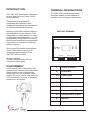
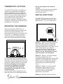
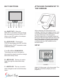
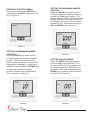
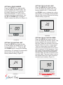
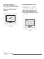
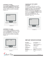
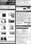
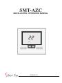
SMT-AZC
INSTALLATION / OPERATION MANUAL
22
o
OFF
VERSION 2.0
www.smarttemp.com
INTRODUCTION
TERMINAL DESIGNATIONS
The SMT-AZC thermostat is designed
to work with the Smart Temp 24Volt
Zone Dampers
The SMT-AZC has dedicated screw
terminals located on the subbase to
facilitate ease of wiring to the actuator
Please take time to read and
understand this manual so that
installation and testing is undertaken in
an efficient and effective manner.
Although great care has been taken in
the preparation of this manual, Smart
Temp takes no responsibility for errors
or omissions contained herein. It is the
responsibility of the installer to ensure
that this thermostat and the equipment
connected to it operate in a safe and
efficient manner.
SMT-AZC SUBBASE
Due to ongoing product improvement,
Smart Temp reserves the right to
change the specifications of the
SMT-AZC without notice.
C R PO PC
DS DS Y W A B
All right reserved.
© Smart Temp Australia Pty Ltd
Intellectual rights apply.
DISASSEMBLY
Insert a small coin in the release slot
located on the bottom of the thermostat.
Gently twist the coin to release the
thermostat from the subbase. Avoid
twisting the case, as this may stress the
LCD and cause it to crack or bend the
terminal pin connectors.
C
24 Volt Common
R
24 Volt Hot
PO
Power Open
PC
Power Close
DS
Duct Sensor
DS
Duct Sensor
Y
Not Applicable in Aust
W
Not Applicable in Aust
A
Modbus
B
Modbus
THERMOSTAT LOCATION
The SMT-AZC should be installed in a
location that represents the ambient
space temperature. Do not install the
thermostat in an area where drafts are
present, near the floor, behind doors or
on an external wall. Avoid placing the
thermostat in areas where the air
movement is limited, affected by direct
sunlight or other areas not typical of the
temperature in the space.
Do not over-tighten the terminal
screws.
Check to see that all wires are landed
correctly and dressed properly to
prevent any shorts.
SWITCH FUNCTIONS
The SMT-AZC contains a set of dip
switches numbered 1 through 8. Only
dip switches 1, 2, 3 and 6 are active.
MOUNTING THE SUBBASE
When mounting the SMT-AZC, be
aware that drafts may travel down wall
cavities and enter the back of the
thermostat through the control wire hole
in the wall. It is important to seal the
hole to prevent any drafts that might
affect the internal temperature sensor.
ON
12345678
......
....
Switch 1 - Switch 1 is used to lock the
thermostat after setup is completed.
When the thermostat is locked (ON
position) a padlock icon will show on the
LCD. When locked, only setpoint
changes and status functions can be
accessed by the user. Do not set
Switch 1 in the ON position until all
setup functions are completed.
C R PO PC
DS DS Y W A B
Pull the control wires through the large
opening in the thermostat subbase then
level and mount the subbase on the wall
using the supplied anchors and screws.
Do not over-tighten the mounting
screws as the subbase may warp
causing improper seating of the
thermostat connecting pins to the
terminal blocks.
Use a properly sized screwdriver and
land each wire to its dedicated terminal.
Switch 2 - Switch 2 is used to display
the space temperature, duct
temperature and setpoint in Celsius (ON
position) or Fahrenheit (OFF position).
Select Celsius or Fahrenheit before
proceeding to the thermostat setup
menu.
Switch 3 - Switch 3 is used to select
two-position (ON position) or fully
modulating (OFF position) damper
control to best suit the specific
application requirement.
Switch 6 - Must be ON for Australia
Model SZ-PS
24Vac
Plug Pack
From Heating / Cooling Equipment
Upstream Sensor
Damper
PO PC
1 2 3
Smart Temp
Belimo
LM24T
Actuator
Damper
Ducting
C R
24Vac
SW 1= OFF
SW 2 = ON
SW 3 = OFF
SW 4 = NA
SW 5 = NA
SW 6 = ON
SW 7 = NA
SW 8 = NA
To downstream vents
DS DS
Y W
A B
Sensor Cool/Heat Modbus
SMT-AZC Zone Control Thermostat
ATTACHING THERMOSTAT TO
THE SUBBASE
KEY FUNCTIONS
A
B
C
D
E
F
A = ON/OFF KEY - When the
SMT-AZC is not locked, this key allows
the thermostat to be turned ON or OFF.
When in the OFF position, the damper
is also driven closed.
B = STATUS KEY - Pressing the
STATUS key displays the UNIT number,
ZONE number, DUCT temperature and
DAMPER position.
When attaching the thermostat to the
subbase, first place the hinged access cover
on by fitting the plastic molded pins into the
grooves at the top of the thermostat.
Carefully align the two standoffs located at
the top of the thermostat with the slots in the
top of the subbase. Allow the thermostat to
swing downward and gently push until the
connector pins are fully seated into the
terminal blocks.
SETUP
C and D = UP and DOWN KEYS These keys are used to increase or
decrease the setpoint as well as change
thermostat setup values.
E = SETUP KEY - This key is used to
toggle through the thermostat setup
menu.
FIGURE 1
F = ENTER KEY - This key is used to
enter changes as well as exit the setup
menu.
Apply 24 Volts power to the thermostat. The
LCD will momentarily display all icons.
(Figure 1)
ENTERING THE SETUP MENU
Press twice and hold the SETUP key
until the word DAMPER appears on the
LCD. (Figure 2)
SETTING THE MAXIMUM DAMPER
POSITION
Press the SETUP key again and the
LCD will display the maximum damper
position for heating and cooling. The
factory default is 100% which means the
damper can drive fully open with a call
for heating or cooling. Position may be
adjusted in 10% increments using the
UP and DOWN keys. (Figure 4)
FIGURE 2
SETTING THE MINIMUM DAMPER
POSITION
Press the SETUP key again and the
LCD will display the minimum damper
position. The factory default is 10%
which means the damper is driven 90%
closed after a heating or cooling call is
satisfied. Press the UP and DOWN keys
to change the minimum damper
position. Position may be adjusted in
10% increments. (Figure 3)
SETTING A UNIT NUMBER
Press the SETUP key again and the
LCD will display the word UNIT. The
factory default is 00. This number can
be used to assign the SMT-AZC to a
particular HVAC unit. Use the UP and
DOWN keys to assign a UNIT number
from 00 to 99. (Figure 5)
FIGURE 3
FIGURE 5
FIGURE 4
SETTING A ZONE NUMBER
Press the SETUP key again and the
LCD will display the word ZONE. The
factory default is 00. This number can
be used to identify each SMT-AZC
thermostat Network or when used in
multiple stand-alone applications. Use
the UP and DOWN keys to assign a
ZONE number from 00 to 99. (Figure 6)
SETTING THE COOLING LIMIT
Press the SETUP key again and the
LCD will display the cooling limit. The
factory default is 68° F. Press the UP
and DOWN keys to change the cooling
limit setting. It is strongly recommended
that the limit not be set below the factory
default setting. (Figure 8)
20
LIMiT
o
COOL
FIGURE 8
FIGURE 6
SETTING THE HEATING LIMIT
Press the SETUP key again and the
LCD will display the heating limit. The
factory default is 24° C. Press the UP
and DOWN keys to change the heating
limit setting. It is strongly recommended
that the limit not be set above the
factory default setting. (Figure 7)
24
LIMiT
SETTING THE ACTUATOR SPEED
Press the SETUP key again and the
LCD will display the actuator speed. The
factory default is 90 seconds which is
the time it takes the actuator to drive the
damper blade fully open or fully closed.
This is a critical step in the SMT-AZC
setup since the thermostat can be used
with a variety of 24 Volt actuators. If you
are unsure of the actuator speed, place
the actuator in the fully closed position
and then apply 24 Volts to common and
normally open. The time it takes to drive
the damper blade fully open equals the
actuator speed setting. (Figure 9)
o
HEAT
FIGURE 7
When using Smart Temp Model LMU-24T
set speed to 45 Seconds
FIGURE 9
SETTING THE MODBUS ADDRESS
Press the SETUP key again and the
LCD will display the Modbus
communications address. The factory
default is 01. The SMT-AZC has
integrated Modbus communications
capability for remote monitoring and
control.
For more information on Modus
Communications, contact Smart Temp
at (03) 9763 0094 or
[email protected] (Figure 10)
TEMPERATURE CALIBRATION
OFFSET
Press the SETUP key again and the
LCD will display the temperature
calibration offset. The factory default
setting is 0. Typically, it is not necessary
to adjust the temperature calibration
offset as the SMT-AZC has been factory
calibrated. If calibration is necessary, a
high quality electronic digital
thermometer must be used. Place the
thermometer sensor probe next to the
thermostat sensor and allow five
minutes before comparing the
temperature readings. Use the UP and
DOWN keys to adjust the temperature
calibration. The range is +/- 10° C.
(Figure 11)
FIGURE 10
FIGURE 11
SENSOR
LOCATION
SAVING SETTINGS AND EXITING THE
SETUP MENU
Press the ENTER key and the SMT-AZC
will save the setup menu settings and exit
the program. The LCD will display the
space temperature along with other
normal operating functions. To review the
thermostat settings, simply press and hold
the SETUP key until the setup menu is
displayed and then toggle through the
settings. Press the ENTER key to exit the
setup menu. Remove the thermostat from
the subbase and set Switch 1 in the ON
position to lock the thermostat which will
prevent setup changes from being made.
When the thermostat is locked, a padlock
icon will be displayed on the LCD.
(Figure 12)
CHECKING THERMOSTAT
STATUS POINTS
After the thermostat is locked and
operational, its status functions can be
checked by pressing the STATUS key
twice and toggling through the following
status points:
UNIT - Displays the HVAC unit number
assigned to thermostat.
ZONE - Displays the thermostat zone
number.
DUCT - Displays the duct temperature.
DAMPER - Displays the damper position
in one degree increments.
(0% = fully closed and 100% = fully open)
THERMOSTAT OPERATION
22
o
The SMT-AZC is designed to provide
accurate but simple temperature control
for the user. When the thermostat is not
calling, only the space temperature is
displayed on the LCD along with the
padlock icon that confirms the thermostat
setup functions can not be changed. The
user can use the UP and DOWN keys to
change the thermostat setpoint within the
setpoint limits and review the status
points by pressing the STATUS key.
(Figure 13)
FIGURE 12
HELPFUL HINT
If it is necessary to exit the setup menu
before all setup functions are completed,
simply press the ENTER key and all
settings will be saved.
To re-enter the setup menu, press and
hold the SETUP key until the word
DAMPER appears and then continue
pressing the SETUP key to toggle through
the functions to where you left off.
22
o
FIGURE 13
CHANGING THE SETPOINT
When the UP and DOWN keys are
ADVANCED FUNCTIONS
pressed, the thermostat will display the
DAMPER POSITION OVERRIDE
The SMT-AZC has a damper position
override feature to assist in air
balancing and bypass damper setup.
With the thermostat unlocked, press
twice and hold the SETUP key until the
word DAMPER appears on the LCD.
(Figure 15)
word SET. The setpoint then can be
changed within the setpoint limits.
(Figure 14)
22
o
SET
FIGURE 14
FIGURE 15
OVERRIDE TO OPEN
Press the UP and DOWN keys until the
word OPEN appears on the LCD and
then press the ENTER key. The damper
will drive open and remain in the open
position until the override is cancelled.
(Figure 16)
CANCELLING THE DAMPER
OVERRIDE
In order for the SMT-AZC to control
normal damper operation, the override
must be cancelled. Press and hold the
SETUP key until the word DAMPER
OPEN or DAMPER CLOSE appears on
the LCD. Use the UP or DOWN key until
only the word DAMPER is displayed and
then press the ENTER key. The
thermostat will then resume normal
operation. Figure 18)
FIGURE 16
OVERRIDE TO CLOSE
Press the UP and DOWN keys until the
word CLOSED appears on the LCD and
press the ENTER key. The damper will
drive closed and remain in the closed
position until the override is cancelled.
(Figure 17)
FIGURE 18
SMT-AZC SPECIFICATIONS
FIGURE 17
Input Voltage
Relay Rating
Operating Temperature
Operating RH
Size
LCD Display Size
Temperature Sensor
Accuracy
Display Resolution
Control Range
Back Light
Back Light Life
Communications Protocol
Approvals
Warranty
24 VAC 50/60 Hz
24 VAC @ 1Amp per relay
23° F to 122° F
0-95% (non-condensing)
4-7/16” W x 4-1/16” H x 7/8” D
2-3/4” W x 1-7/8” H
10K NTC type 3
+/- 1° F @ 77° F
1° F
36° F to 96° F
Blue EL (Electro Luminescent)
3,000 hours to half brightness
Modbus
FCC (Part 15) (Pending) C-tick
3 Years
06-1050-051410