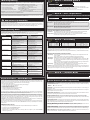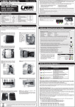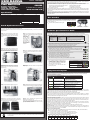
1
RA00xxx Pearl Mod+Stock Version: 21.05.12 © Nosram 2012 #90999 Brushless Competition Modified + Stock Profiles Linear BEC 6.0V/3.0A USB Software Updateability for distributor address, see packaging www.nosram.com Specifications yes yes 30.5 x 33mm 3.7 - 7.4V yes Star 6.0V / 3.0A yes X-Brake 3way Protection-System SmartTemp-Readout System 3 Blue LED Plugged Fan USB Software Updateability 4 adjustable Modes (SCS2, Dual XPSMOD+STOCK, Autobrake) yes yes yes yes yes yes, #92501 yes • Upgrade for ALL Pearl and Pearl V2 speed-controls • Perfect for Modified- AND Stock-Racing • Easy Plug-In Conversion Please read the following instructions carefully before you start using your speed control. This user guide contains important notes for the safety, the use and the maintenance of this product. Thus protecting yourself and avoid damages of the product. Proceed according to the user guide in order to understand your speed control better. Please take your time as you will have much more joy with your product if you know it exactly. This user manual shall be kept in a safe place. If another customer is using this product, this manual has to be handed out together with it. User Interface As known from Nosram, fast & simple trackside adjustments are a must have and therefore we continue using our user interface using two buttons and several LED‘s which indicate you correct operation, the mode‘s and settings you have selected, etc. A inside the LED symbolises a flashing LED. * Specifications subject to change without notice. • Bulletproof 6V/3A Linear BEC • 125% faster microcontroller • includes all tools and hardware red blue yellow Pure Brushless Competition Forward/Brake Footprint Voltage Input Modified + Stock Profiles Compatible winding styles Linear BEC Boost-0 Mode Thank you for your trust in Nosram products. This unique Nosram Pearl Mod+Stock logicboard allows you to turn your existing Pearl speed-controls (no matter what version) into the very latest modified + stock competition speed-control by simply replacing the existing logicboard of your speed-control. This new Pearl Mod+Stock manual is an addition to your existing Pearl speed-controls manual, the parts of the manual about installation, wiring and warning notes have not been integrated into this additional manual. green USER MANUAL MODE button & LED Board Replacement Process The replacement of your speed-controls existing logicboard with the new Pearl Mod+Stock logicboard is really simple using this guide and the supplied hardware & tools. Only caution needs to be taken on the various pins (so you don‘t bend those) and that you do work on a clean and dry work table. Step1: start by removing the 4 small screws from the bottom of your speed-control, using the supplied screwdriver. Then remove bottom case. Step3: your speed control consists of powerboard, upper case and cooling hardware now. only. Be careful that the small plastic inserts, which activate the buttons, are still in place. Step5: align the 11pin connector on logic- and power-board, make sure there is no „offset“ between pins. Do not fully push the boards together now! Step2: you now have access to the existing logicboard, which is plugged into the powerboard with two connector rows on each side. Slowly and gently pull the board, side by side using your fingers to grip the edges of the board, until the logicboard is loose and can be removed. Step4: start installing Pearl Mod+Stock logicboard by guiding receiver- and switch wire to opening in housing first. Step6: align the two 2pin connectors on opposite side as well now, (red/blue/yellow) SET button & LED (green) Calibrate Speed-Control to Radio In setup mode the speed-control stores every step (e.g. learning your radios neutral and endpoints) by pressing the SET button. All the settings will be stored in the memory even if it will be disconnected from the battery. TRANSMITTER SETTINGS: Setup the following basic functions on your transmitter (if available): Throttle Travel Brake Travel Throttle Exponential Neutral Trim Servo Reverse High ATV, EPA Low ATV, EPA, ATL EXP, EXPO SUB Trim Throttle Reverse 100% 100% start with 0 centre any setting, don‘t change after set-up procedure! If your transmitter doesn‘t offer any of above functions, it‘s already in „basic setup“ mode. • Ensure that the speed-control is not connected to the drive battery and is switched off. • Remove motor pinion or ensure that the wheels of the model are free to rotate. • Switch the transmitter on and set the transmitter throttle stick to neutral. • Connect the speed-control to the battery and switch the unit on. • Hold SET button pressed for at least 3sec. Green SET LED will be on while you press SET button and once it entered radio calibration both blue and green LED‘s will flash (the green LED will continue flashing during entire setup procedure). • Leave transmitter in neutral position and press the SET button once. Neutral setting is stored , MODE LED flashes yellow. • Hold full throttle on transmitter and press SET button once. Full-throttle setting is stored, MODE LED flashes red. • Hold full brake on transmitter and press SET button once. Full-brake setting is stored, LED‘s glow red (MODE) and green (SET). • This completes the setup procedure and your Pearl Mod+Stock is ready to use. If you make a mistake during the setup procedure, don‘t worry: Disconnect the battery for about 10sec and start again from the first step. • For storage of the car, disconnect the drive battery at any time! Function Status Neutral Neutral (when „Boost Zero“ enabled) partial throttle full throttle partial brake full brake Forward Brake 3way Protection System green red blue yellow informs you about the cause of the shutdown by special LED flashing sequence, the green SET LED will flash quickly to indicate there is an error and the MODE LED‘s will tell you the „error code“ (= cause for shutdown). Error Code LED flashing sequences: Error Type Possible Reason Motor Thermal Shutdown Step7: push both boards together firmly now. 1. too high settings for Mode3 power-profiles? 2. too high gear ratio? 3. too low motor wind for application? 4. too high mechanical motor timing? Battery Low Voltage Cut-Off 1. battery empty or wrong setting in ACS2? 2. battery damaged? 3. motor too strong for battery discharge capability? 4. poor connection (bad connector, bad soldering joint)? Speed-Control Thermal Shutdown 1. too high settings for Mode3 power-profiles? 2. too high gear ratio? 3. too low motor wind for application? Locked Rotor protection 1. defective motor (rotor does not spin)? 2. drivetrain stuck? Sensor Wire Issue 1. sensor wire missing or defective? Step8: doublecheck both plastic button activators are still in place before closing your speed-control again! Active power reduction at critical temperatures: in case you‘re getting near critical motor- or speedcontrol temperature the speed-control will automatically switch to „Boost0“ mode during operation. This function allows you to finish your run or at least reach the pitlane at slightly reduced speed. Info: the critical temperature, at which this protection triggers, is considered as 9 flashes! You can easily indicate this has happened in case the blue LED flashes (which means the speedo is in „Boost0 mode“) after the run, even tough you started with boost enabled. For your next run (after switching off/on) your choosen profiles will be active again and not „Boost0“. Step9: close your speed-control again by attaching the new lower case (as supplied), you recognise the new type by the extra pocket in the middle. Step10: you‘ve completed the upgrade to Pearl Mod+Stock succesfully, now. Please follw our manual/guide about the correct usage of your updated speed-control in order to benefit from the latest improvements! The crossed-out wheeled bin means that within the European Union the product must be taken to seperate collection at the product end-of-life. Do not dispose of these products as unsorted municipal waste. SmartTemp-Readout System 2: allows you to read-out the maximum internal temperature that the speedo and motor have reached during the run. You can convienently read-out the temperature back in the pits since it remains stored until you turn it on the next time regularly (which will reset the memory). This feature allows you to accurately check if all is running well or if you‘re close to shutdown already. Shutdown occurs at 10 flashes and you should not exceed 8 flashes during normal use for both motor- and speedcontrol temperature. Please adjust your profiles, gearing and motor accordingly, so you stay within these safe limits. Every flash below 10 equals to 5°C temperature decrease. Caution: motor temperature read-out only works if motor has a built-in NTC temperature sensor! At your own risk: if you wish to disable motor temperature cut-off completely you can do so by using value 0 in Mode.1. We call this function „Hardcore Racing Mode“. as it also disables the cell-voltage cut-off completely. The speed-controls thermal cut-off can not be disabled! How to read-out the temperature: switch in „OFF“ position, keep MODE button pressed while you turn switch to „ON“ (then release button). at first speed-control temperature will be indicated • count the number of flashes of the green LED (other LED‘s must be off). to change to motor temperature read-out, press MODE button one more time. • count the number of flashes of the green LED (other LED‘s must be off). Temperature chart (speed-control and motor temperature): #1 > -45°C > -81°F #2 -40°C -72°F #3 -35°C -63°F #4 -30°C -54°F #5 -25°C -45°F #6 -20°C -36°F #7 -15°C -27°F #8 -10°C -18°F #9 -5°C -9°F #10 Shutdown Mode Programming *** Mode.1 *** SmartCell System 2 The Pearl Mod+Stock features 4 modes which enable you to adjust it 100% to YOUR special requirements. The factory settings are shown in grey colour. • How to get into „programming the modes“ Press MODE button for 3 or more seconds. • How to check the stored values Count the number of flashes of the green SET-LED (* = value 1 | ** = value 2 | etc.). • How to change the value Press SET button to increase value by one step. • How to get to the next Mode Press MODE button once. • How to leave the programming mode If you are in MODE.4, press the MODE button one more time, which will also store the settings! Important: do not turn the switch off before leaving Mode 4 (by one more press of MODE button) as otherwise your recent changes won‘t be stored in the memory of the Pearl Mod+Stock! Take your time to understand the different mode‘s and it‘s parameters, profiles and functions. Otherwise you will not fully benefit from the latest achievements built into this speed-control. ! USB Software Updateability Be aware that the Pearl Mod+Stock can only be updated with the latest USB-Bridge Spec.2 (#92501) and is not supported by the older #92500 USB-Bridge! The new #92501 bridge does support all previous speed-controls as well of course. Through the sensor connector the speed-control can be updated to the latest firmware available for download at www.Nosram.com. The optional USB-bridge and a computer are required to do so, please refer to exact details in USB Bridge manual. Troubleshooting Guide To eliminate all other possibilities or improper handling, first check all other components in your model and the trouble shooting guide before you send in this product for repair. If products are sent in for repair, which do operate perfectly, we have to charge a service fee according to our pricelist. Always check error by checking LED error code first, this gives you a good indication were to search! Symptom Cause Remedy Motor overheats False settings on Mode‘s 2 and/or 3 Too high mechanical motor timing Too little motor cooling Wrong Gear ratio False settings on Mode‘s 2 and/or 3 Transmitter settings changed after set-up Power Capacitor damaged Motor or sensor-board in motor defective Speed-control defective Speedo plugged in incorrectly Multiprotection System activated Wiring problem Sensor wire missing/defective Motor defective Speedo defective Speedo connected to receiver with wrong polarity Wiring problem Battery defective Crystal, receiver or transmitter defective Speedo defective Sensor wire defective Motor or sensor board in motor defective Radio interference Power capacitor damaged Speedo defective Model with reversed gearbox! Adjust settings of Mode‘s 2 + 3 Decrease mechanical motor timing Add cooling fan and/or heatsink Adjust gear ratio Adjust settings of Mode‘s 2 + 3 Repeat set-up procedure Replace Power Capacitor Replace sensor-board or motor Send in product for repair Plug speedo to receiver as Ch.2 Check settings for your application Check wires and connectors Install/replace sensor wire Replace motor Send in product for repair Connect speedo with correct polarity Check wires and connectors Replace with different battery pack Replace components one by one Send in product for repair Replace sensor wire Replace sensor board or motor Change location of components Replace power capacitor Send in product for repair Can not use a sensored brushless system! Wrong setting in ACS2 (Mode.1)! Model used too often without cool-down periods Motor stronger than motorlimit or input voltage too high Stuck drivetrain or ball-bearing Motor defective Transmitter settings changed after set-up Humidity/water in speedo Motor or sensor board in motor defective Receiver or antenna too close to power wires, motor, battery or speedo. Receiver aerial too short or coiled up Receiver defective, too sensitive; Transmitter defective, transmitter output power too low, servo problem Poor battery connection Transmitter batteries empty Change value of SCS2 (Mode.1) accordingly Let cool down after every run Use only motors and batteries which are within the specifications of the speed-control Maintain model Replace motor Repeat set-up procedure Immediately unplug and dry speedo Replace sensor board or motor See „Installation Tips“ and „Installation“ Insufficient performance. E.g. poor power, topspeed or brake Servo is working, no motor function No servo and no motor function Motor stutters while accelerating Motor runs in reverse when accelerating forward on radio Speed-control switches off frequently Motor never stops, runs at constant slow speed Radio interference Remark Cut-Off Voltage use for Motor Temp Cut-Off #0 disabled #1 3.2V 1S LiPo [°C] #2 #3 4.0V 6.4V 2S LiFe 2S LiPo 110°C (230°F) WorksDefault setting is 2S LiPo, so if you use other batteries you need to adjust Mode.1 before first use! When the battery voltage reaches the selected cut-off voltage, the motor function will be disabled and the LED‘s will indicate that the shutdown has occured due to undervoltage of your batteries.. Important: Using value #0 in this mode will also disable the motor temperature cut-off function! *** Mode.2 *** Feel / Torque Control Remark Initial Drive Torque Timing Boost0 operation Units [%] [°] #1 3 #2 6 #3 9 20 no #4 12 #5 15f #6 3 #7 6 #8 9 0 yes #9 12 #10 15f There are two separate groups, which you need to choose from, based on motor type and class as the torque timing is different. Within the 2 groups the profiles vary by the initial drive settings only. Group A (1-5) for use with Nosram Pure2, Pure & Cobra motors, best efficiency & torque with those motors. higher value means quicker initial response. not complying with Boost0 Racing rules! Group B (6-10) for use with all other motors (Nosram Storm, LRP X11, Novak, Tekin, SP, Orion, Epic, GM etc) higher value means quicker initial response. fully complying with Boost0 Racing rules! Explanation about the Mode.2 parameters functions: - Initial Drive: also called minimum drive, this is the level in % where the throttle will start from the lowest trigger position from your radio. Higher value means more aggressive response. - Torque Timing: this function should only be enabled (profiles 1-5 = 20°) for Pure/Pure2 motors, it results in more efficient running and higher torque with those motors. flash at same time *** Mode.3 *** Boost Timing Remark Boost Timing Boost Trigger Boost Angle Turbo Timing use for motors Units [°] [RPM] [°/kRPM] [°] #0 #1 5 #2 10 disabled Boost0 #3 #4 15 20 7600 0,5 0 Modified #5 25 #6 25 #7 30 2,5 3,0 #8 35 5100 3,5 10 Stock #9 40 #10 45 4,0 4,5 Again, there are two groups of profiles, this time they are split into profiles suited for modified- (1-5) and stockmotors (6-10). Make sure you use the correct ones for your application, as wrong profile group for your motor will either result in poor performance or overheating of your motor! Important: Boost0 racing is only possible when choosing profile #0 in Mode3 (+ profiles 6-10 in Mode2 of course!). Explanation about the Mode.3 parameters functions: - Boost Timing: - Boost Trigger: - Boost Angle: - Turbo Timing: adjusts the speed-controls dynamic boost timing in degrees, which is applied to the motor ba- sed on it‘s RPM. Higher number results in more overall power & RPM, but also higher temperature. RPM at which Boost Timing will become active, below this RPM there is 0° timing. this number is given in degrees per 1000RPM, so for each RPM increase of your motor by 1000 the speed-control will increase it‘s dynamic timing by the set value until the set „Boost Timing“ has been reached. Higher number means more aggressive timing engagement as higher timing is reached at lower RPM, also higher number will usually increase motor temperature. only enabled for stock profiles (6-10)! Applies 10° of extra turbo timing when set „Boost Ti- ming“ level has been reached + you apply full throttle on the radio. Important: be aware that settings need to match your motor well. In case you use a low rpm motor and a high boost value, it is possble that the final „Boost Timing“ can not be achieved with a low „Boost Angle“ value and therefore speed might not be as imagined or „Turbo Timing“ might never engage! Replace components one by one Only use original manufacturers crystals Check plugs and connecting wires Replace / recharge transmitter batteries Units [V] flash alternatively *** Mode.4 *** Automatic Brake Remark Brake strength Units [%] #0 0 #1 3 #2 6 #3 9 #4 12 #5 15 #6 20 #7 25 #8 30 #9 35 #10 40 allows you to set a slight braking action when your trigger is in neutral range Repair Procedures / Limited Warranty All products from NOSRAM are manufactured according to the highest quality standards. NOSRAM guarantees this product to be free from defects in materials or workmanship for 90 days (non-european countris only) from the original date of purchase verified by sales receipt. This limited warranty doesn’t cover defects, which are a result of misuse, improper maintenance, outside interference or mechanical damage. „This applies among other things on: • Cut off original power plug or not using reverse polarity protected plugs • Receiver wire and/or switch wire damaged • Mechanical damage of the case • Humidity/Water inside the speed control • Mechanical damage of electronical components/PCB • Soldered on the PCB (except on solderpads) • Connected speed-control with reversed polarity“ To eliminate all other possibilities or improper handling, first check all other components in your model and the trouble shooting guide, if available, before you send in this product for repair. If products are sent in for repair, which do operate perfectly, we have to charge a service fee according to our pricelist. With sending in this product, the customer has to advise NOSRAM if the product should be repaired in either case. If there is neither a warranty nor guarantee claim, the inspection of the product and the repairs, if necessary, in either case will be charged with a fee at the customers expense according to our price list. A proof of purchase including date of purchase needs to be included. Otherwise, no warranty can be granted. For quick repair- and return service, add your address and detailed description of the malfunction. If NOSRAM no longer manufactures a returned defective product and we are unable to service it, we shall provide you with a product that has at least the same value from one of the successor series. The specifications like weight, size and others should be seen as guide values. Due to ongoing technical improvements, which are done in the interest of the product, NOSRAM does not take any responsibility for the accuracy of these specs. NOSRAM-Distributor-Service: • • • • Package your product carefully and include sales receipt and detailed description of malfunction. Send parcel to your national NOSRAM distributor. Distributor repairs or exchanges the product. Shipment back to you usually by COD (cash on delivery), but this is subject to your national NOSRAM distributor‘s general policy. Special Features (further explanations) Boost0 Racing: the blue MODE LED will flash in neutral trigger position, to indicate that entire timing advancement is disabled for „true stock racing“, as required by certain federations. Boost0 is enabled with following Mode2/Mode3 combinations: - Mode.2: #6, #7, #8, #9 or #10 - Mode.3: #0 Linear BEC: a powerful linear 6V/3A output has been integrated, which offers bulletproof + stable voltage to the receiver + servo. Important: be aware that the Pearl Mod+Stock does not have an integrated booster and therefore for 1S applications a separate receiver pack is required. Lower Motor Temperatures: our further improved commutation algorithm and imporved hardware result in reduced motor operating temperatures then when other speed-controls are used. Adaptive Brake Response: newly revised X-Brake with sharper response and super-linear feeling! A good starting point for the brake setting on your radio is 80% for all classes. Make sure you do the radio-setup with all settings on the radio on 100%! Fading Compensation: a special algorithm compensates the feeling that the car may act slightly different with fully charged batteries vs. semi-full batteries. This algorithm takes that into account and compensates for that offset, so the feeling should remain closely the same for the entire run. Changing Mode Settings without the Transmitter: simply disconnect the receiver lead from the receiver and change the MODE settings on the speed-control as described under „Mode Programming“. Works-Default-Settings: All Nosram speed-controls come factory-adjusted (defaults are grey-shaded). If you loose track of the modes, you can restore the works default settings easily. With your radio switched on, hold the SET button pressed while you switch on the speed-control. This returns the unit to our works default settings. Power Capacitor: Never run without a power-capacitor! It is needed for protection and increases punch, it must be connected to BAT+ and BAT- solderpads with shortest possible wires.