1
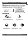
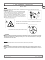
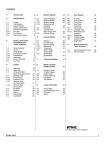
EN
SP
TBC-255SFK
OWNER’S MANUAL
Read the manual carefully before
operating this machine.
INTRODUCTION
EN
Thank you for your purchase of the Tanaka 3-in-1 professional yard maintenance kit. The easy quick-connect
design allows you to efficiently switch between the various tools for different jobs and one commercial quality engine
powers all of the equipment.
Please take the time to carefully review all of the information accompanying your new equipment. A complete
understanding of the product and its uses will make for a more enjoyable and productive experience.
Power equipment can be dangerous. Use good judgment when operating the tools, and most importantly – read and
understand all of the safety precautions prior to operating. Be sure that anyone else who may be operating this
equipment has received and reviewed the manual.
An exploded parts illustration is available on the Tanaka website, www.tanakapowerequipment.com. Always use
genuine Tanaka replacement parts and accessories.
If you have any questions as to the function or safety of the equipment seek professional guidance either from your
Tanaka dealer or from Tanaka direct at 1-888-482-6252 or www.tanakapowerequipment.com.
In addition to the attachments included with your TBC-255SFK, the following attachments and accessories can be
purchased to add to its versatility:
TSW-210 Power Sweeper Attachment
TMC-200 Mini-cultivator Attachment
TPH-210 Articulating Pole Hedge Trimmer Attachment
TBC-255SFK
2
2’ and 3’ Pole Saw Extensions
Owner’s Manual
IMPORTANT SAFETY INFORMATION
WARNING! • Read the Operator’s Manual and follow all warnings and safety instructions. Failure to do so can
result in serious injury to the operator and /or bystanders. • Objects may be thrown or ricochet in all directions.
ALWAYS WEAR EYE PROTECTION. • Keep bystanders at least 50 feet (15m) away. • To reduce the chance of
hearing loss, always wear ear protection. • To reduce the risk of injury from loss of control, never use a metal blade on
a curved shaft grass trimmer. Never use a metal blade on any brushcutter without barrier bar or bicycle handle
configuration and safety strap. • Use of a blade may cause a sudden sideways, forward or backward motion of the
brushcutter when the blade contacts a solid object. See Owner’s manual for model specific details.
WARNING
Before using your new unit
Read the operators manual carefully.
Check that the cutting equipment is correctly
assembled and adjusted.
Start the unit and check the carburetor adjustment.
See “Mainentenace”.
The engine exhaust from this product
contains chemicals known to the State
of California to cause cancer, birth
defects and other reproductive harm.
Meanings of symbols or labels.
It is important that you read, fully understand and
observe the following safety precautions and
warnings. Careless or improper use of the unit
may cause serious or fatal injury.
Always wear eye, head, and ear
protectors when using this unit.
TBC-255SFK
Read, understand, and follow all
warnings and instructions in this
manual and on the unit.
Gloves should be worn when
necessary, e.g. when assembling cutting equipment.
3
Use anti-slip and sturdy
footwear.
Owner’s Manual
EN
TABLE OF CONTENTS
EN
1. Carton Contents………………………………
5
2. Key Features and Components....................
6
3. Warnings and Safety Instructions……..........
7
4. General Operation………………...................
8
5. Unit Assembly & Operation
Brush Cutter………………………………..
9-11
Edger Attachment………………………….
12
Polesaw Attachment………………………
13-15
6. Maintenance…………………………………
Brush Cutter……………………………….
16-17
Edger Attachment………………………....
18
Polesaw Attachment………………………
18
Maintenance Schedule…………………...
19
7. Warranty……………………………………….
20-21
8. Specifications……………………………….…
22
TBC-255SFK
4
Owner’s Manual
1. CARTON CONTENTS
1.
2.
3.
4.
Engine
Joint Case Assembly
Trimmer Attachment
Safety Guard (not attached in box)
5.
6.
7.
8.
Edger Attachment
Edger Wheel Assembly(not attached in box)
Pole Saw shaft
Pole Saw Assembly (not attached in box)
1. Joint Case Assembly
2. Safety Guard Assembly
3. Nylon Line
4. 2.6 oz bottle of Tanaka Oil
5. Edger Blade (spare)
6. Strap
TBC-255SFK
5
Owner’s Manual
EN
2. KEY FEATURES AND COMPONENTS
EN
1. Fuel Cap
2. Throttle Trigger
3. Starter Handle
4. Blade Guard
5. Cutting attachment
6. Drive Shaft Tube
7. Handle Bar
8. Ignition switch
9. Throttle lock
10. Safety Trigger
11. Choke lever
12. Engine
13. Angle transmission
14. Joint Case
TBC-255SFK
6
Owner’s Manual
3. WARNINGS AND SAFETY INSTRUCTIONS
If situations occur which are not
covered in this manual, take care
and use common sense. Contact
your dealer if you need assistance.
Pay special attention to statements
preceded by the following words:
WARNING!
Indicates a strong possibility of severe
personal injury or loss of life, if
instructions are not followed.
NOTE!
Helpful information for correct function
and use.
CAUTION!
Indicates a possibility of personal injury
or equipment damage, if instructions
are not followed.
CAUTION!
Do not disassemble the recoil starter.
You may get a possibility of personal
injury with recoil spring.
Operator Safety
- Always wear a safety face shield or
goggles.
- Always wear heavy, long pants, boots
and gloves. Do not wear loose clothing,
jewelry, short pants, sandals or go
barefoot. Secure hair so it is above
shoulder length.
- Do not operate this tool when you are
tired, ill or under the influence of
alcohol, drugs or medication.
- Never let a child or inexperienced
person operate the machine.
- Wear hearing protection.
- Never start or run the engine inside a
closed room or building. Breathing
exhaust fumes can kill.
- Keep handles free of oil and fuel.
- Keep hands away from cutting
equipment.
- Do not grab or hold the unit by the
cutting equipment.
- When the unit is turned off, make sure
the cutting attachment has stopped
before the unit is set down.
- When operation is prolonged, take a
break from time to time so that you may
avoid possible whitefinger disease
which is caused by vibration.
Unit / Machine Safety
- Inspect the entire unit/machine before
each use. Replace damaged parts.
- Check for fuel leaks and make sure all
fasteners are in place and securely
tightened.
TBC-255SFK
- Replace parts that are cracked,
chipped or damaged in any way before
using the unit/machine.
- Make sure the safety guard is properly
attached.
- Keep others away when making
carburetor adjustments.
- Use only accessories as
recommended for this unit/machine by
the manufacturer.
WARNING!
Never modify the unit/machine in any
way. Do not use your unit/machine
for any job except that for which it is
intended.
Fuel Safety
- Mix and pour fuel outdoors and where
there are no sparks or flames.
- Use a container approved for fuel.
- Do not smoke or allow smoking near
fuel or the unit/machine or while using
the unit/machine.
- Wipe up all fuel spills before starting
engine.
- Move at least 3 m away from fueling
site before starting engine.
- Stop engine before removing fuel cap.
- Empty the fuel tank before storing the
unit/machine. It is recommended that
the fuel be emptied after each Use.
WARNING!
Antivibration systems do not
guarantee that you will not sustain
whitefinger disease or carpal tunnel
syndrome. Therefore, continual and
regular users should monitor closely
the condition of their hands and
fingers. If any of the above
symptoms appear, seek medical
advice immediately.
- Keep all parts of your body away from
the muffler and cutting attachment
when the engine is running.
- Keep cutting attachment below waist
level.
Store unit/machine and fuel in area
where fuel vapors cannot reach sparks
or open flames from water heaters,
electric motors or switches, furnaces.
etc.
Maintenance safety
- Maintain the unit/machine according to
recommended procedures.
- Disconnect the spark plug before
performing maintenance except for
carburetor adjustments.
- Keep others away when making
carburetor adjustments.
- Use only genuine Tanaka replacement
parts as recommended by the
manufacturer.
Transport and safety
- Carry the unit/machine by hand with
the engine stopped and the muffler
away from your body.
- Allow the engine to cool, empty the
fuel tank, and secure the unit/machine
before storing or transporting in a
vehicle.
- Store unit/machine out of the reach of
children.
- Clean and maintan the unit carefully
and store it in a dry place.
- Make sure engine switch is off when
transporting or storing.
Cutting Safety
- Do not cut any material other than
grass and brush.
- Inspect the area to be cut before each
use. Remove objects which can be
thrown or become entangled.
- For respiratory protection, wear an
aerosol protection mask when cutting
the grass after insecticide is scattered.
- Keep others including children,
animals, bystanders and helpers
outside the 15 m hazard zone. Stop the
engine immediately if you are
approached.
- Always keep the engine on the right
side of your body.
- Hold the unit/machine firmly with both
hands.
- Keep firm footing and balance. Do not
over-reach.
7
Owner’s Manual
EN
4. GENERAL UNIT OPERATION
EN
Fuel
WARNING!
The trimmer is equipped with a two-stroke engine. Always run the engine on fuel which is mixed
with oil. Provide good ventilation, when fueling or handling fuel.
- Always use branded 89 octane unleaded gasoline.
- Use Tanaka two-cycle oil with a mix of 50:1.
- If Tanaka oil is not available, use an anti-oxidant added quality oil expressly labeled for air-cooled 2cycle engine use (JASO FC GRADE OIL or ISO EGC GRADE.)
- Do not use BIA or TCW (2-stroke liquid cooled type) mixed oil.
- Never use multi-grade oil (10 W/30) or waste oil.
- Always mix fuel and oil in a seperate clean container.
- Always start by filling half the amount of fuel, which is to be used. Then add the whole amount of oil.
Mix (shake) the fuel mixture. Add the remaining amount of fuel.
- Mix (shake) the fuel-mix thoroughly before filling the fuel tank.
Fueling
WARNING!
Always shut off the engine before refueling.
- Slowly open the fuel tank, when filling up with fuel, so that possible over-pressure disappears.
- Tighten the fuel cap carefully after fueling.
- Always move trimmer at least 3m (10ft.) from the fueling area before starting.
- Before fueling, clean the tank cap area carefully to ensure that no dirt falls into the tank.
- Make sure that the fuel is well mixed by shaking the container, before fueling.
TBC-255SFK
8
Owner’s Manual
5. UNIT ASSEMBLY & OPERATION
Power Head Assembly
Brush Cutter
EN
The TBC-255SFK utilizes one engine to power all of the various attachments. The top portion of the shaft (closest to the
engine) is common to all of the attachments. The brushcutter shaft (lower portion), requires set-up as follows:
1
1.
Remove all of the product contents from the carton. Identify the engine with the shaft and handle
attached as shown :
2. Locate the lower section of brushcutter shaft as shown:
3. Before the lower shaft assembly can be joined to the
upper shaft, it is necessary to install the coupler onto
the upper shaft. Carefully place all three washers over
the end of the shaft protruding fro m the shaft
assembly on the engine side as depicted:
With all the washers in place over the end of the shaft,
place the connector over the shaft end with the
washers so the locator bolt (1) on the connector is
aligned with the locator hole on the shaft. After the
locator bolt is secured, tighten the connector to the
shaft using the pinch bolt (2).
With the connector assembled to the upper shaft, you
can now attach the lower shaft assembly as described
in the next section.
4. The lower bruschutter section comes with the No-Brainer cutting
head attached. Place the opposite end of the shaft into the
coupler on the upper shaft as depicted:
5. Make sure the shaft is fully inserted and that the locking bolt is
properly aligned with the location hole and that the tightening
knob is securely tightened. Failure to properly connect the
shaft sections will result in damage to the shaft and possible
injury to the operator.
6. Install the safety guard onto the shaft as shown. Use caution
when handling the safety guard as the shield uses a sharp line
limiter blade.
CAUTION
Your TBC-255SFK is categorized under the ANSI safety standard B175.3, as a “convertible grass trimmer”. This means
that while your machine does not come equipped as blade capable, it is possible to convert it for use with a steel blade
(commonly referred to as a “brushcutter”). By purchasing the blade kit (Tanaka part number 748503), you will have the
necessary components to safely use a blade. These components include a blade capable debris shield,
barrier bar, safety strap and blade retaining hardware.
NEVER ATTEMPT TO USE THIS MACHINE WITH A STEEL BLADE WITHOUT FIRST PROPERLY
CONVERTING THE UNIT TO A BLADE CAPABLE BRUSHCUTTER!
TBC-255SFK
9
Owner’s Manual
5. UNIT ASSEMBLY & OPERATION
Line Trimmer Operation
Brush Cutter
EN
BE SURE YOU HAVE READ AND UNDERSTAND THE GENERAL WARNINGS AND SAFETY INSTRUCTIONS
DESCRIBED IN SECTION 3.
Cutting Safety
a.
b.
Do not cut any material other than grass and brush.
Inspect the area to be cut before each use. Remove any objects which can be thrown or can become
entangled.
c. For respiratory protection, wear an aerosol protection mask, especially if any insecticide or other chemical
agents have been dispersed.
d. Always wear a safety face shield or goggles.
e. Always wear heavy, long pants, boots and gloves. Do not wear loose clothes, jewelry, short pants, sandals or
go barefoot. Secure hair so it is above shoulder length.
f. Do not operate the tool if you are tired, ill or under the influence of alcohol, drugs or medication.
g. Never let a child or inexperienced person operate the machine.
h. Never start or run the engine inside an enclosed room or building. Exhaust fumes can kill.
i. Keep handles free of oil and dirt.
j. Keep hands away from cutting attachments. When the unit is turned off, make sure the cutting attachment has
stopped before the unit is set down.
k. When operation is prolonged, take a break form time to time so that you may avoid possible white-finger
disease which is caused by vibration.
l. Wear hearing protection.
m. Keep all others bystanders, including children and pets outside the 15 meter hazard zone. Stop the engine
immediately if you are approached.
n. Always keep the engine on the right side of your body.
o. Hold the machine firmly with both hands.
p. Keep all parts of your body away from the muffler and cutting attachment when the engine is running.
q. Keep firm footing and balance. Do not over-reach.
r. Keep cutting attachment below waist level.
Starting
CAUTION!
Before starting, make sure the cutting attachment does not touch anything.
1.
2.
3.
4.
Set ignition switch (1) to ON postion.
**Push priming bulb (4) several times so that the fuel flows through return pipe.
Set choke lever to CLOSED position (5).
Pull recoil starter briskly, taking care to keep the handle in your grasp and not
allowing it to snap back.
When you hear the engine want to start, return choke lever to RUN position (open).
Then pull recoil starter briskly again.
NOTE!
If the engine does not start, repeat procedures from 2 to 4.
5.
After starting engine, allow engine about 2-3 minutes to warm up before subjecting it to any load.
TBC-255SFK
10
Owner’s Manual
5. UNIT ASSEMBLY & OPERATION
Brush Cutter
EN
Cutting
When cutting, operate engine at over 6500 rpm. Extended time of use at low rpm may wear out the clutch
prematurely.
Cut grass from right to left.
If using a steel blade, thrust may occur when the spinning blade
contacts a solid object in the critical area. A dangerous reaction
may occur causing the entire unit and operator to be thrust
violently. This reaction is called BLADE THRUST. As a result, the
operator may lose control of the unit which may cause serious or
fatal injury. Blade thrust is more likely to occur in areas where it is
difficult to see the material to be cut.
The blade turns counterclockwise, therefore, be advised to operate the unit
from right to left for efficient cutting.
Keep onlookers out of working area at least 15m (50 ft.).
WARNING!
If cutting attachment should strike against stones or other debris, stop the engine and make sure that the
attachment and related parts are undamaged. When grass or vines wrap around attachment, stop engine
and attachment and remove them.
Stopping
Decrease engine speed and run at an idle for a few minutes, then turn off ignition switch.
WARNING!
A cutting attachment can injure while it continues to spin after the engine is stopped or power control is
released. When the unit is turned off, make sure the cutting attachment has stopped before the unit is set
down.
TBC-255SFK
11
Owner’s Manual
5. UNIT ASSEMBLY & OPERATION
Edger Attachment
EN
Edger Assembly
The edger attachment comes assembled with the exception of
attaching the wheel to the blade guard assembly. Using the
carriage bolt included with the wheel, attach to the blade guard
bracket as shown.
By loosening the safety guard assembly bolts (shown as reference
number 3), the angle of the guard can be adjusted for preference. Be
sure that the guard does not come off of the gear case lip on which it is
intended to ride. Attempting to tighten it in place when incorrectly
positioned can cause damage.
Edger Operating Procedures
Before proceeding with this section, BE SURE YOU HAVE READ AND UNDERSTAND THE GENERAL
WARNINGS AND SAFETY INSTRUCTIONS DESCRIBED IN SECTION 3.
Use only for edging the type of grass and other growth for which the machine is designed.
1. Adjust the wheel within the guard bracket as depicted:
Adjust cutting depth by loosening knob nut (1) and moving location of wheel
up or down. To increase cutting depth, move wheel location upwards and to
decrease , move it lower. After the location is decided, tighten knob nut (1)
securely.
NOTE!
All adjustments should be made after engine has stopped completely,
stop switch is in the OFF position and cutting attachment has stopped
turning.
2. Always hold unit firmly with both hands and keep body well balanced.
3. Always operate the edger positioned with the engine on the right side of the
operator.
WARNING!
Operate the unit from a position where guard blocks the line of sight to the
cutting blade.
WARNING!
If blade should strike against stones or other debris, stop the engine and
visually inspect the blade, guard and related parts for any damage.
TBC-255SFK
12
Owner’s Manual
5. UNIT ASSEMBLY & OPERATION
Polesaw Attachment
EN
Pole Saw Assembly
The pole saw attachment requires that the gear case be mounted to the shaft. The shaft is marked with “SF-PS”.
One end of the inner shaft is splined, while the other end is square. As with all of the attachments, the square end is
designed to fit into the shaft coupler. The splined end is where the gear case mounts.
Loosen the locator screw (1) and set screw (3).
Insert the shaft tube into the gear case. Because
the splines may not immediately align – it requires
the shaft to be rotated until the splines align and
the shaft seats in the gear case. When properly
installed – the decal indicating proper assembly
will appear as indicated :
Pole Saw Operation
Before proceeding with this section, BE SURE YOU HAVE READ AND UNDERSTAND THE GENERAL WARNINGS AND SAFETY INSTRUCTIONS DESCRIBED IN SECTION 3.
WARNING
DANGER
All overhead electrical conductors and
communications wires can have electricity
flow with high voltages. Never touch wires
directly or indirectly when trimming,
otherwise serious injury or death may result.
CAUTION!
Review the area to be trimmed. Look for hazards that could
contribute to unsafe conditions. DO NOT operate unit if any wires
(power, telephone, cable, etc.), are closer than 15M (50ft.) to any
part of the operator or unit.
AVOID ALL POWER LINES.
THIS UNIT IS NOT INSULATED AGAINST ELECTRICAL CURRENT!
Spectators and fellow workers must be warned, and children
and animals prevented from coming nearer than 15M (50ft.),
while pole saw is in use.
Always wear head protection with full face shield to help protect
against falling branches or debris.
TBC-255SFK
13
Owner’s Manual
5. UNIT ASSEMBLY & OPERATION
Polesaw Attachment
EN
Pole Saw Operation
Installation of bar and chain.
Install the chain guide bar(1) onto the bolt (2) then push it toward the
sprocket (3) as far as it will go. Make sure the boss of the chain tension
adjuster (4) fits into the hole of the bar(5).
NOTE!
Slightly move the bar back and forth and make sure the chain tension
boss (4) fits into the hole (5) in the bar properly.
Confirm the direction of saw chain (1) is correct as indicated, and align
the chain on the sprocket.
Guide the chain drive links into the bar groove all the way around the bar.
Install the side case (2) onto the guide bar clamp bolt. Thread nut onto
clamp bolt but only tighten by hand.
Raise the bar end, and tighten the chain (1) by turning the tension
adjustment bolt (2) clockwise. To check proper tension, lightly lift up the
center of the chain and there should be about 0.5 – 1.0 mm clearance
between bar and edge of drive link (3).
CAUTION!
PROPER TENSION IS EXTREMELY IMPORTANT!
Raise the bar end and securely tighten the chain bar clamp nut with the
supplied box wrench.
A new chain will stretch so adjust the chain after a few cuts and watch
chain tension carefully for the first half hour of cutting.
CAUTION! Always wear gloves when touching the chain.
TBC-255SFK
14
Owner’s Manual
5. UNIT ASSEMBLY & OPERATION
Polesaw Attachment
EN
Chain Oil
The chain oiler on your pole saw is automatic. When the engine is running, the chain oil is automatically discharged.
Fill oil reservoir with good quality bar and chain oil. Remove the oil reservoir tank cap (1), and fill to the top. Add
chain oil when its level lowers to one centimeter from bottom.
Adjustment of Chain Oil Supply
Loosen the locking screw (2) one turn. Turn the adjusting screw (3)
clockwise to decrease the quantity and turn it counterclockwise to increase
the quantity. Do not turn the adjusting screw (3) clockwise beyond one turn
from its most counterclockwise position or the maximum quantity discharged
position. After adjustment has been made, tighten locking screw (2).
Pole Saw Pruning Techniques
This attachment is designed for trimming small limbs and branches up to 8"
in diameter. Follow these tips for successful operation.
1. Plan cut carefully. Check to see direction branch will fall before
beginning.
2. Long branches should be removed in several pieces.
3. Do not stand directly beneath branch being cut.
4. Look out for branch immediately behind the branch being cut. If pole
saw impacts rear branch – damage to the machine can occur.
5. Apply plenty of throttle to avoid chain catching in the wood.
6. When pruning a limb of 4" in diameter or larger, cut as follows:
a. Undercut limb diameter near tree trunk.
b. Finish top cut slightly farther out on limb.
c. Flush cut stub at trunk.
7. Never use the pole saw for bucking or felling.
TBC-255SFK
15
Owner’s Manual
6. MAINTENANCE
Brush Cutter
EN
Carburetor adjustment
WARNING!
The cutting attachment may be spinning during carburetor adjustments.
WARNING!
Never start the engine without the complete clutch cover and tube
assembled! Otherwise the clutch can come loose and cause personal
injuries.
In the carburetor, fuel is mixed with air. When the engine is test run at the
factory, the carburetor is basically adjusted. A further adjustment may be
required, according to climate and altitude. The carburetor has one
adjustment possibility:
T = Idle speed adjustment screw.
Idle speed adjustment (T)
Check that the air filter is clean. When the idle speed is correct, the cutting attachment will not rotate. If adjustment
is required, close (clockwise) the T screw, with the engine running, until the cutting attachment starts to rotate.
Open (counter clockwise) the screw until the cutting attachment stops. You have reached the correct idle speed
when the engine runs smoothly in all positions well below the rpm when the cutting attachment starts to rotate.
If the cutting attachment still rotates after idle speed adjustment, contact your Tanaka dealer.
NOTE!
Standard Idle rpm is 2500~3000 rpm.
WARNING!
When the engine is idling the cutting attachment must under no circumstances rotate.
Air filter
The air filter must be cleaned from dust and dirt in order to avoid:
• Carburetor malfunctions.
• Starting problems.
• Engine power reduction.
• Unnecessary wear on the engine parts.
• Abnormal fuel consumption.
Clean the air filter daily or more often if working in exceptionally dusty areas.
Cleaning the air filter
Remove the air filter cover and the filter (1). Rinse it in warm soap suds. Check that the filter is dry before
reassembly. An air filter that has been used for some time cannot be cleaned completely. Therefore, it must regularly
be replaced with a new one. A damaged filter must always be replaced.
TBC-255SFK
16
Owner’s Manual
6. MAINTENANCE
Brush Cutter
EN
Fuel Filter
Drain all fuel from fuel tank and pull fuel filter line from tank. Pull filter
element out of holder assembly. Replace filter if it appears to be discolored
or hardened from use. The filter has a white, felt-like appearance when
new.
Spark Plug
The spark plug condition is influenced by:
• An incorrect carburetor setting.
• Wrong fuel mixture (too much oil in the gasoline)
• A dirty air filter.
• Difficult running conditions (such as cold weather).
These factors cause deposits on the spark plug electrodes, which may result in
malfunc¬tion and starting difficulties. If the engine is low on power, difficult to start
or runs poorly at idling speed, always check the spark plug first. If the spark plug
is dirty, clean it and check the electrode gap. Readjust if necessary. The correct
gap is 0.6 mm. The spark plug should be replaced after about 100 operation
hours or earlier if the electrode is badly eroded.
NOTE!
In some areas, local law requires using a resistor spark plug to suppress ignition
signals. If this machine was originally equipped with resistor spark plug, use the
same type of spark plug for replacement.
Muffler
Remove the muffler and clean any excess carbon
from the exhaust port or muffler inlet every 100
hours of operation.
Cylinder (Engine cooling)
The engine is air cooled, and air must circulate freely around engine and over
cooling fins on cylinder head to prevent overheating.
Every 100 Operating hours, or once a year (more often if conditions require),
clean fins and external surfaces of engine of dust, dirt and oil deposits which
can contribute to improper cooling.
NOTE!
Do not operate engine with engine shroud or muffler guard removed as this
will cause overheating and engine damage.
Angle transmission (brushcutter and edger only)
Check the gear case grease level about every 50 hours of operation by removing the grease filler plug on the side of
the case.
If no grease can be seen on the flanks of the gears, fill the transmission with a quality lithium based multipurpose
grease up to 3/4.
Do not completely fill the transmission.
TBC-255SFK
17
Owner’s Manual
6. MAINTENANCE
Edger Maintenance
Edger / Polesaw Attachments
EN
Blade
WARNING!
Wear protective gloves when handling or performing maintenance
on the blade.
When replacing blade, use genuine Tanaka replacement blade with a one
inch (25.4mm), center arbor hole.
Discard blades that are bent, cracked, warped, broken or damaged in
any way.
Gear Case
Check gear case for grease level after every 50 hours of use. Remove the
grease filler plug on the side of the gear case. If no grease can be seen
on the flanks of the gears, fill with a quality lithium based multipurpose
grease. Fill to about ¾ - do not completely fill.
Edger Blade Replacement
1. Take off the left-handed nut (1) and cutter holder cap (2) from
the blade shaft.
2. Install blade on the shaft and then replace the cutter holder
cap and nut in order.
NOTE!
When installing cutter holder cap (2), be sure to set concave
side facing blade.
3. Insert the locking bar (4) into the hole of the cutter holder (5)
and the gear case by lining up each hole.
4. Tighten the blade nut securely (clockwise to loosen/counter
clockwise to tighten)
Pole Saw Maintenance
Before each use, clean the chain oiler port (1) and bar groove.
Check gear case for grease level about every 50 hours of operation by removing the grease filler plug on the side of
the gear case.
TBC-255SFK
18
Owner’s Manual
6. MAINTENANCE
General
EN
Maintenance schedule
Below you will find some general maintenance instructions.
For further information please contact your service dealer.
Daily maintenance
·
Clean the exterior of the unit.
·
Check that the harness is undamaged.
·
Check the blade guard for damage or cracks. Change the guard in case of impacts or cracks.
·
Make sure the cutting attachment is properly centered, sharp, and without cracks. An off-centered
cutting attachment induces heavy vibrations that may damage the unit.
·
Make sure the cutting attachment nut is sufficiently tightened.
·
Make sure the blade transport guard is undamaged and that it can be securely fastened.
·
Check that nuts and screws are sufficiently tightened.
Weekly maintenance
·
Check the starter, especially cord and return spring.
·
Clean the exterior of the spark plug.
·
Remove it and check the electrode gap. Adjust it to 0.6 mm, or change the spark plug.
·
Clean the cooling fins on the cylinder and make sure the air intake at the starter is not clogged.
·
Make sure the gear case is filled with grease up to ¾ full.
·
Clean the air filter.
Monthly maintenance
·
Clean the exterior of the carburetor and the space around it.
TBC-255SFK
19
Owner’s Manual
7. WARRANTY
TANAKA KOGYO CO., LTD. SMALL OFF ROAD ENGINE
TWOYEAR LIMITED WARRANTY
EN
EMISSION RELATED PARTS, FOR TWO YEARS FROM THE DATE OF ORIGINAL DELIVERY OF THE SMALL OFF ROAD ENGINE, TANAKA (THE
COMPANY), THROUGH ANY TANAKA DEALER, WILL REPAIR OR REPLACE, FREE OF CHARGE, FOR THE ORIGINAL AND EACH SUBSEQUENT
PURCHASER, ANY PART OR PARTS FOUND TO BE DEFECTIVE IN MATERIAL AND/OR WORKMANSHIP. EMISSIONRELATED PARTS ARE:
THE CARBURETOR ASS’Y, IGNITIONCOIL ASS’Y, MAGNETOROTOR, SPARKPLUG WIRES, SPARKPLUG, FUEL TANK, FUELFILTERS, AIRFILTERS,
FUELPIPE, CATALYTIC MUFFLER (ON APPLICABLE MODELS), AND ALL GASKETS.
HOWEVER SPARKPLUGS, AIRFILTER, FUELFILTER ARE WARRANTED TILL THE FIRST REPLACEMENT POINT.
ALL OTHER PARTS EXCEPT ABOVE PARTS, FOR TWO YEARS OF HOME USE (ONE YEAR FOR ANY OTHER USE), FROM THE DATE OF ORIGINAL
DELIVERY OF THE SMALL OFF ROAD ENGINE, TANAKA (THE COMPANY), THROUGH ANY TANAKA DEALER, WILL REPAIR OR REPLACE, FREE OF
CHARGE, FOR THE ORIGINAL PURCHASER, ANY PART OR PARTS FOUND TO BE DEFECTIVE IN MATERIAL AND/OR WORKMANSHIP. THIS IS
THE EXCLUSIVE REMEDY.
THE PURCHASER SHALL BEAR COSTS OF TRANSPORTING THE UNIT TO AND FROM THE TANAKA DEALER.
THE PURCHASER SHALL NOT BE CHARGED FOR DIAGNOSTIC LABOR WHICH LEADS TO THE DETERMINATION THAT A WARRANTY PART IS
DEFECTIVE, IF THE DIAGNOSTIC WORK IS PERFORMED AT THE TANAKA DEALER.
THE PURCHASER OR OWNER IS RESPONSIBLE FOR THE PERFORMANCE OF THE REQUIRED MAINTENANCE AS DEFINED BY THE
MANUFACTURER IN THE OWNNER’S MANUAL.
ANY WARRANTED PART WHICH IS NOT SCHEDULED FOR REPLACEMENT AS REQUIRED MAINTENANCE, OR WHICH IS SCHEDULED ONLY FOR
REGULAR INSPECTION TO THE EFFECT OF “REPAIR OR REPLACE AS NECESSARY” SHALL BE WARRANTED FOR THE WARRANTY PERIOD. ANY
WARRANTED PART THAT IS SCHEDULED FOR REPLACEMENT AS REQUIRED MAINTENANCE FOR THE PERIOD OF TIME UP TO THE FIRST
SCHEDULED REPLACEMENT POINT FOR THAT PART. ANY SUCH PART REPAIRED OR REPLACED UNDER WARRANTY WILL BE WARRANTED FOR
THE REMAINDER OF THE PERIOD PRIOR TO THE FIRST SCHEDULED REPLACEMENT POINT FOR THE PART.
ANY REPLACEMENT PART THAT IS EQUIVALENT IN PERFORMANCE AND DURABILITY MAY BE USED IN NONWARRANTY MAINTENANCE OR
REPAIRS, AND SHALL NOT REDUCE THE WARRANTY OBLIGATION OF THE COMPANY.
THE COMPANY IS LIABLE FOR DAMAGES TO OTHER ENGINE COMPONENTS CAUSED BY THE FAILURE OF A WARRANTED PART STILL UNDER
WARRANTY.
THIS WARRANTY DOES NOT APPLY THOSE UNITS WHICH HAVE BEEN DAMAGED BY NEGLIGENCE OF INSTRUCTION LISTED IN THE OWNER’S
MANUAL FOR PROPER USE AND MAINTENANCE OF THE UNITS, ACCIDENT MISHANDLING, ALTERATION, ABUSE, IMPROPER LUBRICATION,
USE OF ANY PARTS OR ACCESSORIES OTHER THAN THOSE SPECIFIED BY THE COMPANY, OR OTHER CAUSES BEYOND THE COMPANY’S
CONTROL.
THIS WARRANTY DOES NOT COVER THOSE PARTS REPLACED BY NORMAL WEAR OR HARMLESS CHANGE IN THEIR APPEARANCE.
THERE ARE NO OTHER EXPRESS WARRANTIES.
IMPLIED WARRANTIES INCLUDING THOSE OF MERCHANTABILITY AND FITNESS FOR A PARTICULAR PURPOSE ARE LISTED TO TWO YEAR
FROM THE ORIGINAL DELIVER DATE.
LIABILITIES OF INCIDENTAL OR CONSEQUENTIAL DAMAGE UNDER ANY AND ALL WARRANTIES ARE EXCLUDED.
SOME STATES DO NOT ALLOW LIMITATIONS ON HOW LONG AN IMPLIED WARRANTY LASTS OR EXCLUSION OR LIMITATION OF INCIDENTAL
OR CONSEQUENTIAL DAMAGES SO THE ABOVE LIMITATION OR EXCLUSION MAY NOT APPLY TO YOU.
THIS WARRANTY GIVES YOU SPECIFIC LEGAL RIGHTS, AND YOU MAY ALSO HAVE OTHER RIGHTS WHICH VARY FROM STATE TO STATE.
IF YOU NEED TO OBTAIN INFORMATION ABOUT THE NEAREST AUTHORIZED SERVICE DEALER, PLEASE CALL TANAKA KOGYO CO., LTD. C/O
INTERNATIONAL SALES & MARKETING, INC. (253) 3331200.
IMPORTANT: YOU WILL RECEIVE A WARRANTY REGISTRATION CARD AT TIME OF PURCHASE. PLEASE FILL OUT THE CARD AND SEND IT TO
TANAKA AMERICA, 1028 4th STREET SOUTH WEST, AUBURN, WA 98001.
BE SURE TO KEEP A COPY FOR YOUR RECORDS.
TBC-255SFK
20
Owner’s Manual
7. WARRANTY
EPA PHASE2/CALIFORNIA EMISSION CONTROL
WARRANTY STATEMENT
EPA, THE CALIFORNIA AIR RESOURCES BOARD AND TANAKA KOGYO CO., LTD. ARE PLEASED TO
EXPLAIN THE EXHAUST AND EVAPORATIVE EMISSION CONTROL SYSTEM WARRANTY ON YOUR
TANAKA SMALL OFF ROAD ENGINE. NEW SMALL OFF ROAD ENGINES MUST BE DESIGNED,
BUILT AND EQUIPPED TO MEET STRINGENT EPA PHASE2/CALIFORNIA ANTISMOG STANDARDS.
TANAKA KOGYO CO., LTD. MUST WARRANT THE EMISSION CONTROL SYSTEM ON YOUR SMALL
OFF ROAD ENGINE FOR THE PERIODS OF TIME LISTED BELOW PROVIDED THERE HAS BEEN NO
ABUSE, NEGLECT OR IMPROPER MAINTENANCE OF SMALL OFF ROAD ENGINE.
YOUR EMISSION CONTROL SYSTEM INCLUDES PARTS SUCH AS THE CARBURETOR, FUEL TANK,
IGNITION SYSTEM AND CATALYTIC CONVERTER.
WHERE A WARRANTABLE CONDITION EXISTS, TANAKA KOGYO CO., LTD. WILL REPAIR YOUR
SMALL OFF ROAD ENGINE AT NO COST TO YOU INCLUDING DIAGNOSIS, PARTS AND LABOR.
ANY SUCH PART REPAIRED OR REPLACED UNDER WARRANTY WILL BE WARRANTED FOR THE
REMAINDER OF THE PERIOD PRIOR TO THE FIRST SCHEDULED REPLACEMENT POINT FOR THE
PART.
MANUFACTURE’S WARRANTY COVERAGE:
THE 1995 AND LATER SMALL OFF ROAD ENGINES ARE WARRANTED FOR TWO YEARS. IF
ANY EMISSION RELATED PART ON YOUR ENGINE IS DEFECTIVE, THE PART WILL BE
REPAIRED OR REPLACED BY TANAKA KOGYO CO., LTD.
OWNER’S WARRANTY RESPONSIBILITIES:
AS THE SMALL OFF ROAD ENGINE OWNER, YOU ARE RESPONSIBLE FOR THE
PERFORMANCE OF THE REQUIRED MAINTENANCE LISTED IN YOUR OWNER’S MANUAL.
TANAKA KOGYO CO., LTD. RECOMMENDS THAT YOU RETAIN ALL RECEIPTS COVERING
MAINTENANCE ON YOUR SMALL OFF ROAD ENGINE, BUT TANAKA KOGYO CO., LTD.
CANNOT DENY WARRANTY SOLELY FOR THE LACK OF RECEIPTS OR FOR YOUR FAILURE
TO ENSURE THE PERFORMANCE OF ALL SCHEDULED MAINTENANCE.
AS THE SMALL OFF ROAD ENGINE OWNER, YOU SHOULD BE AWARE, HOWEVER, THAT
TANAKA KOGYO CO., LTD. MAY DENY YOU WARRANTY COVERAGE IF YOUR SMALL OFF
ROAD ENGINE OR A PART HAS FAILED DUE TO ABUSE, NEGLECT, IMPROPER
MAINTENANCE OR UNAPPROVED MODIFICATIONS.
YOU ARE RESPONSIBLE FOR PRESENTING YOUR LAWN AND GARDEN EQUIPMENT
ENGINE TO A TANAKA KOGYO CO., LTD. SERVICE CENTER AS SOON AS A PROBLEM
EXISTS. THE WARRANTY REPAIRS SHOULD BE COMPLETED IN A REASONABLE AMOUNT
OF TIME, NOT TO EXCEED 30 DAYS.
IF YOU HAVE ANY QUESTIONS REGARDING YOUR WARRANTY RIGHTS AND RESPONSIBILITIES,
YOU SHOULD CONTACT TANAKA KOGYO CO., LTD. C/O INTERNATIONAL SALES & MARKETING,
INC., CUSTOMER SERVICE REPRESENTATIVE AT (253) 3331200.
TBC-255SFK
21
Owner’s Manual
EN
8. SPECIFICATIONS
Model
TBC-255SFK
Engine Size (ml)...........................
24 (1.46 cu. in.)
EN
Spark Plug....................................
Champion CJ6Y or RCJ6Y or equivalent
Fuel Tank Capacity (l)...................
0.67 (22.8 fl. oz.)
Dry Weight (kg).............................
5.4 (11.9 lbs)
Sound Pressure Level (dB(A)).....
92.5
Sound Power Level (dB(A)).........
112
TBC-255SFK
22
Owner’s Manual