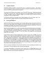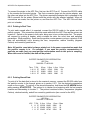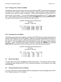
1
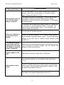
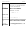
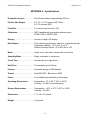
&
Operations Manual
Biotest Diagnostics Corporation
66 Ford Road, Denville, NJ 07834 USA
Tel: 973.625.1300 ● 800.522.0090 ● Fax: 973.625.9454
www.BiotestUSA.com
APC/APC Plus Operations Manual
Version 04-11
TABLE OF CONTENTS
Laser Optics...................................................................................................................... 1
Electrical ...................... ......................................................................................................1
1. Introduction ................. .................................................................................................1
2. APC Plus Description ................................................................................................. 2
3. Operation ..................................................................................................................... 2
3.1 Keypad Functions .................................................................................................2
3.1.1 Particle Size ...............................................................................................3
3.1.1.1 APC Plus.......................................................................................3
3.1.1.2 APC...............................................................................................3
3.1.2 Counting Mode ...........................................................................................3
3.1.3 Start/Stop ...................................................................................................3
3.1.4 Counts or Concentration Display Modes ............... .....................................3
3.1.5 Mode Button ...............................................................................................4
3.1.6 On/Off Button .............................................................................................5
3.1.6.1 Low Power Mode ..........................................................................5
3.1.6.2 Off Mode .......................................................................................5
3.2 General Counting Procedure.................................................................................6
3.2.1 Operating the APC Plus in Pressurized Environments...............................6
3.3 Using the Remote Sampling Probe and Tubing ....................................................6
3.4 Setting Options................... ...................................................................................6
3.4.1 Setting the Sample Time, Clock, Date, and Hold Time ..............................7
3.5 Viewing Stored Sample Data ................................................................................7
3.5.1 Sample Time ..............................................................................................7
3.5.2 Particle Counts ...........................................................................................8
3.5.3 Erasing the Particle Counts ........................................................................8
3.6 Temperature and Humidity Sensors......................................................................8
4. Service Information.....................................................................................................9
4.1 Flow Rate..............................................................................................................9
4.2 Battery...................................................................................................................9
4.2.1 Optional Power Supply .............................................................................10
4.3 Cleaning the Particle Counter .............................................................................10
5. Windows™ Software .................................................................................................10
5.1 Installation ...........................................................................................................10
5.2 Computer Interface .............................................................................................11
5.3 Running APCWIN.exe.........................................................................................11
i
APC/APC Plus Operations Manual
Version 04-11
TABLE OF CONTENTS
6. Accessories ............................................................................................................... 12
6.1 Purge Filter Assembly ......................................................................................... 12
6.2 Serial Dot Matrix Printer ...................................................................................... 12
6.2.1 Printer Set Up........................................................................................... 12
6.2.2 Printing in Real Time ................................................................................ 13
6.2.3 Printing Stored Data ................................................................................. 13
6.2.4 Printing in Per Cubic Foot Mode............................................................... 14
6.2.5 Printing in Per Liter Mode......................................................................... 14
6.3 Bench Top Stand ................................................................................................ 14
6.4 Remote Sample Probe and Tubing ..................................................................... 14
7. Troubleshooting Guide............................................................................................. 15
APPENDIX A – Specifications ....................................................................................... 18
APPENDIX B – Product Warranty.................................................................................. 19
APPENDIX C – Quick Reference Guide ........................................................................ 20
APPENDIX D – European Declaration of Conformity .................................................. 21
APPENDIX E – Year 2000 Compliance.......................................................................... 22
Microsoft® and Windows™ are either registered trademarks or trademarks of Microsoft
Corporation in the United States and/or other countries. Lotus® and 1-2-3® are registered
trademarks of Lotus Development Corporation.
ii
APC/APC Plus Operations Manual
Version 04-11
SAFETY PRECAUTIONS
Laser Optics
The APC Plus and APC Airborne Particle Counters comply with FDA Laser Performance
Standard 21 CFR 1040.10 and 1040.11.
These instruments contain a class IIIb laser diode with a rated power output of 30 milliwatts at
a wavelength in the range of 650 to 690 nanometers. The laser diode is in a closed assembly
inside the sensor case. Warning labels cover all parts that may allow exposure to class IIIb
laser radiation if disassembled.
Note: There are no user serviceable components in the APC Plus or APC. Tamper proof
screws are used to secure the cover to the sensor case. Should the particle counter
need service, please send the complete instrument to an authorized Biotest service
center for repair.
Electrical
The APC Plus and APC contain a 6-volt sealed lead acid battery. A 6-volt/200 milliamp battery
charger, specifically designed for use with lead acid batteries, is provided. The battery charger
has an input voltage of either 120 or 220 volts with a power dissipation of 5.5 VA. When the
battery is fully charged, the battery charger reaches a floating point and the charging process
terminates itself automatically.
The symbol near the battery charger input signifies a direct current (DC) input.
Note: The APC Plus and APC are sensitive instruments. They should not be used in a
manner that is inconsistent with their intended use. This includes using the proper
battery charger, plugging the charger into the intended power receptacle, and
connection to a computer or printer. It also includes using the counter only in a nonexplosive environment, and not using the counter in environments other than
atmospheric pressure air.
1. Introduction
Note: The APC Plus and APC instruments are nearly identical in their operation. This
manual covers the operation of these two instruments. APC Plus will be used to refer to
the common operation of both instruments. Where the operation of the APC instrument
differs from that of the APC Plus, a separate section will indicate the difference.
Therefore, unless otherwise noted, the names APC Plus and APC are interchangeable.
The APC Plus particle counter is a simple yet sophisticated data collection and storage
instrument. The quickest way to learn the basics of operation is to review the general counting
procedure section of this manual [Section 3.2] while operating some of the keypad functions.
However, we recommend you review the entire manual to familiarize yourself with all the
capabilities of the APC Plus.
1
APC/APC Plus Operations Manual
2.
Version 04-11
APC Plus Description
The APC Plus precisely measures the quantity of airborne particles with sizes above a set of
four fixed particle sizes. It also simultaneously provides temperature, relative humidity, sample
time and date data. The instrument is composed of four modules: the sensor, pump, battery,
and electronics.
The sensor module contains the optical components, and temperature and relative humidity
sensor. Within the particle sensor, light emitted from a laser diode is transmitted and shaped
by a series of lenses to a particle-sensing zone. The beam is then absorbed in a light trap.
When a particle enters the sensing zone, it scatters light from the beam. The light that is
scattered is then collected by a second set of lenses and focused onto a solid-state photo
detector. The amplitude of the electrical signal produced by the photo detector is dependent
on the size of the particle in the sensing zone.
The pump module draws air through the isokinetic probe, past the temperature and humidity
sensor, and into the particle-sensing zone at 0.1 cubic feet per minute.
The battery module supports operation of the APC Plus for up to eight hours without a
recharge, depending on the duty cycle of sampling. The sealed lead acid battery has an
output voltage of 6 volts at 1.3 amp hours. The battery is recharged with the supplied charger.
The central processing electronics module regulates the sensor, pump and battery. The
electronics also process the signals from the sensor module, and processes and stores the
data. The electronics also simultaneously maintains communication when connected to an
IBM compatible personal computer.
3.
Operation
Note: Always turn off the power (on/off key) to the APC Plus Airborne Particle Counter
before connecting or disconnecting any cables.
Note: Do not use the APC Plus for sampling air under pressure.
Note: The unit itself must NOT, on any account, be autoclaved, but may be disinfected
by wiping down with alcohol or commercial disinfectants.
3.1
Keypad Functions
Functions are selected through the keypad on the APC Plus front panel. The LCD display
indicates whether a function is currently enabled. The following sections describe each of the
separate functions. The key labels are indicated in bold face type.
2
APC/APC Plus Operations Manual
Version 04-11
3.1.1 Particle Size
3.1.1.1 APC Plus
0.3, 0.5, 1.0 and 5.0 -- The APC Plus detects particles larger than four diameter thresholds:
greater than 0.3, 0.5, 1.0, and 5.0 microns. The information is gathered for all particle
thresholds simultaneously. Any one channel can be displayed on the LCD at any time. When
the APC Plus is turned on, press any one of these four buttons to control the particle size
displayed on the LCD. The current particle range is displayed on the top center of the LCD
readout.
3.1.1.2
APC
The APC instrument detects particles larger than two thresholds: 0.5 and 5.0 microns. The
description of 3.1.1.1 applies with this exception.
3.1.2
Counting Mode
SNGL, AUTO, and CONT—In SNGL (single) mode the instrument will sample for the
preselected counting time then stop.
In AUTO (automatic) mode the instrument will sample for the pre-selected counting time, hold
for the preprogrammed hold period in standby mode, then repeat this sequence continually.
This standby/sample time sequence will be repeated automatically until data is stored at the
200th memory location, or until pressing the START/STOP key to stop the unit.
In CONT (continuous) mode the instrument will sample continuously until START/STOP is
pressed.
To select the mode, simply press the appropriate key.
displayed in the bottom left corner of the LCD.
The currently selected mode is
3.1.3 START/STOP
START/STOP—When the unit is on, press the START/STOP button to begin or end a
counting sequence. While the instrument is sampling COUNTING will be displayed under the
particle counts. However, when the sampler is counting, COUNTING will be displayed at the
bottom of the screen.
3.1.4 Counts or Concentration Display Modes
/FT3 -- Particle counts can be displayed either as an actual count in number of particles, or as
a concentration in particles per cubic foot, or particles per liter. To display particles per cubic
foot, press the /FT3 key. When in this mode, the /FT3 icon will appear on the upper right
corner of the LCD display. To display particles per liter, press the /FT3 key again. The /LITER
icon will appear in the upper right hand corner to indicate that the instrument is displaying
counts in the particles per liter mode. To return to the number of particles counted, press the
/FT3 button again. Nothing will appear on the screen indicating that your counts are in total
particles.
3
APC/APC Plus Operations Manual
Version 04-11
Note: Although the particle concentration information is correct, displaying the data in
the concentration mode may cause erratic readings at the beginning of the sample
period because of statistical variations due to short sample times.*
To calculate particles per cubic foot, the particle count is divided by the volume of air sampled.
*For Example:
If two 5.0-micron particles are detected after 15 seconds of sampling, the instantaneous count in
5.0-micron particles/cubic foot is:
2/(0.25 min * 0.1 cfm) = 80 five micron particles/cubic foot
If another 5 seconds of sample time passes with no additional particles detected, the
instantaneous count in particles per cubic foot changes to:
2/(0.33 min * 0.1 cfm) = 60 five micron particles/cubic foot
Hence, the count in particles per cubic foot can fluctuate greatly and even appear to decrease at
the beginning of the sample time. The count will stabilize further into the sample period.
Note: The particle counter must perform a calculation to convert the particle counts to
concentration. The calculation for concentration in counts per cubic foot is exact.
However, the concentration calculation for particles per liter uses an approximation that
has a maximum error of 0.06% in the final value. This is because of the nature of the
integer calculations used inside the microcontroller in the APC Plus.
Note: To calculate particles per cubic meter you must first perform your counts in
counts per liter. Next, multiply the resulting concentration by 1000 to get particles per
cubic meter.
3.1.5 Mode Button
The MODE button is used to review the count time, time, date, and hold time, and battery
status. To display the count time, press the MODE button. The display will change from the
count or concentration to the current count time. If the unit is currently sampling, you will see
the time incrementing. Otherwise, you will see the count time of the displayed sample, or of
the displayed memory location if sampling has ended.
If the MODE button is pressed again, the current time is displayed indicated by AM or PM on
the right side of the LCD. Pressing the MODE button again will display the date in MM/DD/YY
format.
One more press of the MODE button will display the hold time. If the APC Plus is in the AUTO
mode, and the counter has not yet been started, the display will show the current value of the
hold time. If the unit is counting, the display will show the programmed hold time. But if the
unit is waiting between samples (only in the AUTO mode), the display will show the hold timer
ticking. If you know the hold time, then you will know when the unit will start. Please note that
if the hold time is 5 seconds or less, the pump does not turn off during the hold period. This is
4
APC/APC Plus Operations Manual
Version 04-11
a consideration during portable operation, since the battery will discharge more rapidly.
However, if the hold time is more than 5 seconds, the pump will start 2 seconds before the end
of the hold time is reached to allow both the pump and the laser to stabilize.
Press the MODE button again to display the battery status. This shows the approximate
percentage of the battery charge that is left. For example, a fully charged instrument with a
fresh battery should run for about 5 hours (count time = 1 minute, hold time = 15 seconds). If
the battery status reads about 50%, then the instrument should run for slightly more than 2
hours. If your expected sampling time is close to this value, you should probably recharge the
battery before starting your data acquisition. Note that the run time (i.e., the battery capacity)
will decrease as the battery ages.
3.1.6 ON/OFF Button
The ON/OFF button is used to turn the instrument on and off. There are two modes of “off,”
the “low power” mode and the “off” mode. These modes can be used to protect the battery
and conserve charge during storage.
3.1.6.1 Low Power Mode
In the low power mode, the microcontroller in the unit is turned on so that it maintains the
current date and time. It draws a small amount of power from the battery. For a fully charged
battery with the instrument in the power down mode, the battery will last about 1.5 months.
After this time, the battery must be recharged.
To enter the low power mode, simply press the ON/OFF button when the unit is on. The unit
will continue to track the time and date. If the unit is stored, the battery charge will be
monitored. When the battery reaches a certain value (5.7 volts), the unit will be turned to the
“off” mode to protect the battery. To turn the unit back on, simply press the ON/OFF button.
3.1.6.2 Off Mode
The off mode essentially disconnects the battery from the counter. This mode should be used
for long-term storage. In this mode, the power is disconnected from the microcontroller, and all
functions cease. In order to enter this mode, press and hold down the ON/OFF button for
about 6 seconds. The display will flash “Off” until the button is released. At this point, the unit
will completely turn off.
Note: Wait one minute to turn unit back on.
To turn the unit back on, simply press the ON/OFF button. The unit will turn back on, and
automatically enter the programming mode. This allows you to easily set the clock/calendar.
Note: The data stored in the 200 data locations in memory is not affected during the Off
mode. When the unit is turned back on, the data will again be accessible, and additional
data will be added to the next unused memory location (unless the last sample location
that was written to was location 200, where the data will then be overwritten as usual).
5
APC/APC Plus Operations Manual
Version 04-11
Note: The off mode is for storage. If the unit is turned to the off mode, it cannot be
turned back on for a few minutes. If you put the unit into this mode, you must wait for a
few minutes before you press the ON/OFF button. If you press the ON/OFF button too
soon, the time that you must wait starts over again.
3.2
General Counting Procedure
To begin counting, press the ON/OFF button to power up the unit. The LCD display should
light up. If the LCD display will not turn on, it’s likely your unit needs recharging. The LCD
display will display the latest stored data prior to the last power off.
Select the appropriate operating options on the keypad including the particle size, the display
mode (total particles, particles per cubic foot, or particles per liter) and the sampling mode
(single, automatic or continuous). Update the count time, date and time as necessary using
the MODE and START/STOP key (see section 3.4.1).
Remove the isokinetic probe (the 3” long by ½” diameter black tube) from the carrying case
and screw it into the top receptacle on your APC Plus. Be careful not to over tighten. To
begin counting, press the START/STOP button.
3.2.1 Operating the APC Plus in Pressurized Environments
The APC Plus may be used in pressurized cleanrooms provided the air inlet and outlet are at
the same pressure. Basically, this means keeping the inlet of the isokinetic probe in the same
environment as the rest of the APC Plus. Placing the inlet at a different pressure than the
outlet will affect the airflow through the counter and alter the calibration.
An example of incorrect use might involve measuring the particle counts in a laminar flow hood
that was modified with access ports. If only the isokinetic probe was placed into the access
port, and if the hood was operating at positive pressure, the airflow through the particle counter
would be altered. However, if the entire particle counter was placed in the hood, the inlet and
outlet pressures would be equal, and there would be no error introduced.
3.3
Using the Remote Sampling Probe and Tubing
Remove the remote sampling probe from its package and screw it into the top receptacle of
the APC Plus, being careful not to over tighten. Attach one end of the remote sample tubing to
the open end of the remote sampling probe. Insert the isokinetic probe into the other end of
the remote sampling tubing. Place this end of remote sample tubing at the sampling site. To
begin counting, press the START/STOP button.
Note: Maximum recommended length of remote sample tubing is 5 feet.
3.4
Setting Options
Various operating parameters can be set on the APC Plus using the MODE key. These
include the count time, the clock time and date, and the hold time.
6
APC/APC Plus Operations Manual
Version 04-11
3.4.1 Setting the Sample Time, Clock, Date, and Hold Time
To change the sample time for the SNGL and AUTO collection modes, depress the MODE and
START/STOP keys simultaneously. The Count Time (CT) indicator will appear in the lower
right corner of the LCD while the sample hour starts blinking. Press the DOWN ARROW
button to decrease or the UP ARROW button to increase the hours up to a maximum of seven.
At seven, if the UP ARROW key is pressed again, the hours will “roll over” to zero. At zero, if
the DOWN ARROW key is pressed, the hours will roll under to seven.
After selecting the count hours, press the MODE button again and the count minutes will start
blinking. Repeat the above procedure to change the minutes of the counting period. Press the
MODE button again to change the seconds. Set the count seconds following the same
procedure. Note that the rollover value for minutes and seconds is 59.
Note: If you press and hold either the UP ARROW or DOWN ARROW key, its function
will be repeated rapidly.
After setting the count time, press the MODE button again. This causes the clock hour display
to start blinking. The clock time can be set in the same manner as the count time. Note that
the time is in the 12-hour format, and that PM represents time from 12:00 to 24:00.
After setting the clock, press the MODE button once again. This will cause the date to appear
with the month figure flashing. The date can be changed in the same manner as the sample
time and the clock.
Press the MODE button again. The display will now show the hold time, indicated by the
appearance of the HT icon in the lower right corner of the LCD. The hours digits will then
blink. Set the hold time the same way that the other times and date were set. The maximum
hold time is 23:59:59 (one second less than 24 hours).
After setting the seconds of the hold time, press the MODE button to return to the standard
LCD display mode.
3.5
Viewing Stored Sample Data
3.5.1 Sample Time
The elapsed time of a sample can be viewed either during or after completing a sample. To
view the sample time for the most recent sample (or the one currently being collected) press
the MODE button repeatedly until the CT symbol appears in the bottom right corner of the LCD
display. The actual sample time will appear on the display even if the count was not taken for
the full sample period.
7
APC/APC Plus Operations Manual
Version 04-11
3.5.2 Particle Counts
The APC Plus has the capacity to store 200 samples in memory. The count information is
automatically stored after each sample. Data storage will also take place if the instrument is
manually stopped without completing the full sample time. The actual sample time will be
stored and can be reviewed along with the particle count data for each location.
To view data stored in memory, the particle counter must not be in the counting mode. To
review counts already stored in memory, press the DOWN ARROW button. After each press
of the DOWN ARROW button the message “Loc XXX” will flash on the screen where “XXX” is
the memory location (1 to 200) currently being displayed. If the DOWN ARROW key is held
down, the memory location will decrement rapidly. To return to the last currently occupied
memory location, press the UP ARROW key to go to memory location 1, and then press the
DOWN ARROW button to return to the last memory location.
After calling up a specific location, you can view the particle size counts by depressing the
appropriate particle size buttons (0.3, 0.5, 1.0 or 5.0 for the APC Plus; 0.5 or 5.0 for the
APC). You can view this information in either concentration mode by pressing the /FT3 button
until the indicator on the LCD changes to the preferred mode (see section 3.1.4 to set the
mode). To view the actual count time, depress the MODE button until the CT symbol appears
in the bottom right of the LCD display, showing the actual sample time.
3.5.3 Erasing the Particle Counts
After completing the current data run, and printing or downloading the data, simultaneously
depress the DOWN ARROW and START/STOP button to clear the memory locations. This
will erase all of the data in memory and the instrument will then store the next count in
Location 1. The unit cannot delete individual samples.
Note: Be careful not to depress the DOWN ARROW and START/STOP buttons
simultaneously until you are done reviewing the data. Pressing the DOWN ARROW and
START/STOP buttons simultaneously clears all the memory locations in the APC Plus
and resets the counter to Loc 1 for storage of the next data set!
3.6
Temperature and Humidity Sensors
The APC Plus contains an integrated circuit (IC) that measures both temperature and relative
humidity. The IC is embedded inside the instrument. As a result, the temperature
(represented in °C) and relative humidity (indicated by %RH) displayed on the LCD does not
depict instantaneous responses to changes in temperature and relative humidity.
An important part of the temperature measurement system is the isokinetic probe. The probe
transfers heat to or from the temperature sensor. With the isokinetic probe installed, and air
flowing through the particle counter in either the AUTO mode or the CONT mode, the readings
will stabilize in about 10 minutes for both temperature and relative humidity. The response
time will be significantly longer if there is no airflow. Therefore, for optimum response from the
temperature and relative humidity sensor, the isokinetic probe should be firmly attached, and
the unit should be run for at least 10 minutes before accurate readings can be obtained. This
is especially true for large changes in temperature and relative humidity.
8
APC/APC Plus Operations Manual
Version 04-11
The above should also be considered when using the remote sampling probe, if there is a
significant temperature differential between the sampling location and the actual location of the
APC. The temperature displayed will be somewhere between the temperature at the sampling
location and that of the APC Plus location.
4.
Service Information
Note: There are no user serviceable components in the APC PLUS. Tamper proof
screws are used to secure the cover to the sensor case. Send the complete instrument
to an authorized Biotest service center for repair and calibration. Failure to follow the
manufacturer’s recommendations may result in damage to the APC PLUS, and will void
the warranty.
Note: The particle counter contains a high power laser in the lens tube that can cause
blindness if optics are opened and mishandled. The optics should only be serviced by
authorized and trained personnel.
Note: The APC Plus is calibrated at the factory using isotropic polystyrene spheres
according to the procedures outlined in ASTM F-328 and ASTM F-649.
It is
recommended that the instrument be returned to the factory annually for calibration.
4.1
Flow Rate
The APC Plus operates at a sampling flow rate of 0.1 cubic foot per minute. Maintaining the
power to the pump at a fixed level controls the flow rate. The flow rate is not user adjustable.
4.2
Battery
The APC Plus is equipped with a 6 volt sealed lead acid battery, which supplies power to the
vacuum pump, laser, and all of the electronics. A battery charger is supplied that is designed
specifically for this battery. The normal recharge time for the battery is up to 5 hours,
depending on how deeply discharged the battery is. An overnight recharge is recommended
when possible.
When the battery is discharged to the point that it cannot produce the necessary voltage for
normal operation of the APC Plus, a low battery indicator will blink on the LCD (the display will
show “lo bat” on the main digits). The counter cannot be used to take samples in this situation.
In this case, plug in the battery charger and let the battery charge for 5 or 10 minutes before
trying to use the instrument. This will restore proper operation to the instrument if it is used
with the charger plugged in.. If the battery was deeply discharged, it may require a longer
charging time to restore instrument function. If the battery charger is left plugged into the
instrument, then the APC Plus can be used to acquire a few samples. The battery should be
completely recharged before a large number of samples are attempted. Also, if the unit is to
be operated continuously in the AUTO mode, then the optional power supply must be used
(please see section 4.2.1).
If the charger is not attached, the instrument will eventually turn itself off. It will not turn back
on until the charger is connected, and a sufficient charge is restored to the battery.
9
APC/APC Plus Operations Manual
Version 04-11
Note: It is recommended to keep the particle counter plugged into the battery charger,
and the charger plugged in whenever the APC Plus is not in use.
Note: If the unit is on or in the Low Power Mode (section 3.1.6.1), the circuitry inside of
the APC Plus draws a small amount of power from the battery to keep the
clock/calendar up to date. If the particle counter is to be stored for extended periods,
the battery may become deeply discharged. The battery will be ruined if the battery is
not charged periodically. It is recommended to charge the unit overnight once a month
to avoid damaging the battery. If possible, leave the unit plugged into the battery
charger to keep the battery charged. If the unit will not be used for more than a few
days use the Off mode (refer to section 3.1.6.2 for a description of the Off mode).
4.2.1 Optional Power Supply
To operate the unit continuously in the AUTO mode for an extended period of time, the
standard battery charger cannot supply enough power. The battery alone will power the unit
for up to 8 hours, depending on the duty cycle of usage. Plugging in the standard charger will
extend the operating time to approximately two days if the battery is in good condition and
initially fully charged. To run the unit longer, Biotest offers an optional power supply that will
run the particle counter indefinitely.
4.3
Cleaning the Particle Counter
The particle counter may be cleaned by using isopropyl alcohol or most commercial
disinfectants. Gently wipe the exterior with a moistened wipe. Under no circumstances should
liquids be poured into or onto the APC Plus, or should the unit be submerged in any liquid. Do
not autoclave the particle counter. Any of these procedures will cause extensive damage to
the unit and will require factory servicing.
5.
Windows™ Software
APCWIN.exe. runs on Windows 95™ or greater. It allows you to display the counts,
temperature, humidity, and clock/calendar data on the computer screen. It also allows you to
download the data from the particle counter memory. This data may then be saved to a file, or
copied to the Windows™ clipboard, where it may then be pasted into any other application that
uses the clipboard. A help system is included to answer potential questions.
The software requires Windows 95™ or greater, 10 megabytes of hard disk space, and an
SVGA monitor.
5.1
Installation
The software is supplied on 1 CD-Rom. To install the program, insert the CD into your CDRom drive. Click on “My Computer” and select the icon representing this CD. Select the
Setup.exe icon and then proceed through the installation.
10
APC/APC Plus Operations Manual
5.2
Version 04-11
Computer Interface
An RS-232 cable is required to link the APC Plus to a personal computer. This cable is
included with the APC Plus. No additional hardware is required to connect the particle counter
directly to an IBM compatible personal computer.
To connect the APC Plus to the computer, turn off the APC Plus power. Attach the male end
of the cable to the APC Plus. Attach the other end of the interface cable connector directly to
an IBM compatible personal computer through any standard RS-232 serial port that is
configured as COM 1 through COM 9.
For computers with 25 pin connectors, use a cable or adapter of the “null modem” type. You
will need a cable or adapter with DB-25 female and DB-9 male connectors.
5.3
Running APCWIN.exe
Connect the APC Plus to the computer with the serial cable, and turn the particle counter on.
Click on the “Start” button, then “Programs”, and then the APC Win program group (or the
group that you selected if you renamed the folder during the installation procedure). Then click
on APCWin with the Biotest logo icon to start the program.
The first time the program is run, it will automatically search all valid serial ports in the range of
COM 1 through COM 9 for the particle counter. If it is unable to communicate with the particle
counter, it will display a message asking you if you want to quit or try again. If you click OK,
the program will try each port again. If you click Cancel, the program will stop trying and
display the main window.
If the program is still not communicating with the particle counter, click on Setup in the main
window. If you know for certain which serial port that the particle counter is connected to,
select that port, and exclude all other ports. Otherwise, select Auto and do not exclude any
ports. Then click on the OK button. The program should then establish communications. If
the “APC/APC Plus” message box is displayed informing you that no communications were
established, click the OK button to try again. If this still fails, turn off the particle counter and
turn it back on. If this fails, quit the program and start it again. If it still fails, check that you
have the cable properly connected to the serial port and plugged into the particle counter.
Turn off the counter, and then turn it back on.
When the program establishes communications with the counter, the display will switch to the
main window. All current data from the counter will be displayed.
To set the clock/calendar on the particle counter, simply click on the Set Clock button in the
main window. This will set the time and date on the counter to match that of the computer.
Make sure the clock on the computer is properly set.
11
APC/APC Plus Operations Manual
Version 04-11
The main use of this program is intended to be to download data from the particle counter’s
memory to the computer. To accomplish this, click on the Download button in the main
window. This will open the download data window. Click on Download | Go on the menu to
start a download. The program will indicate the status of the download in the status bar at the
bottom of the window. When the download is completed, the data may be saved to a file by
clicking on File | Save, and then selecting a filename. The data is saved in the comma
separated values format. The default delimiter is a comma (,). To change this, see the help
system in the program. The data may also be copied to the clipboard, where it may be pasted
into any other Windows™ program that uses the clipboard. Simply click on Edit | Copy on the
menu, and the data will be copied to the clipboard.
Note: This window will not close if the data is not saved. If you try to close the
download window without saving the data, you will be warned. You may then save the
data and close the window, or you may indicate that you do not want to save the data.
6.
Accessories
6.1
Purge Filter Assembly
The purge filter assembly allows you to check the background readings of the APC Plus to
determine if the system has a leak or if the optics need to be cleaned. To attach the purge
filter assembly, unscrew the isokinetic probe, and screw the filter connector into the threaded
insert at the top of the APC Plus. Be sure the purge filter seats firmly against the O-ring.
To test the background reading of the system, turn on the APC Plus with the purge filter
assembly in place. Allow the unit to run for five minutes to clear any loose particles from the
system. Turn the APC Plus off and restart it in the total particles mode and the lowest site
channel. The reading should remain low (less than 10) in a one minute sample. If the unit
registers considerably higher readings, charge the battery. If the unit still fails, check the seal
of the O-ring. If it fails once again, it may be time to have the unit serviced.
The purge filter assembly may also be used to clean the system when moving from a less
clean area (i.e., class 100,000) to a cleaner area (i.e., class 1,000). By running the APC Plus
for about five minutes with the purge filter assembly installed, any loose particles which might
have diffused into the optical system due to use in a dirty environment will be cleaned. If
particles are still registering, continue to purge the particle counter.
6.2
Serial Dot Matrix Printer
6.2.1 Printer Set Up
The serial thermal printer uses the RS-232 interface cable that is supplied with the APC Plus.
The serial interface is compatible with several types of serial printers. Biotest supplies a very
convenient thermal printer that works well for portable use of the APC Plus.
12
APC/APC Plus Operations Manual
Version 04-11
To connect the printer to the APC Plus, first turn the APC Plus off. Connect the RS-232 cable
to the counter and the serial printer. The 9-pin connector plugs into the printer adapter, and
the other end plugs into the APC Plus. The printer requires the adapter that is attached to the
DB-9 connector on the printer (Biotest sells the printer with this adapter installed). When all
connections are made, turn the printer on, and then the APC Plus. The APC Plus will then
print out a header.
6.2.2 Printing in Real Time
To print each sample after it is acquired, connect the RS-232 cable to the printer and the
particle counter. This connection should be made while both the APC Plus and the printer are
turned off. Switch on the power to both units, being sure to turn on the printer first. The printer
will respond by printing a header, which contains the date, the count time and sampling
parameters. Begin sampling. Each time the particle counter pauses or stops, a printout of the
data will automatically occur showing the time, temperature, relative humidity (degrees
Celsius) and counts by particle size.
Note: All particle count data is always printed out in the same concentration mode that
the particle counter is in. For example, if you need the particle concentrations in
particles per cubic foot, you must get the concentration mode to this prior to sampling.
When the count is finished, the data will be printed.
BIOTEST DIAGNOSTICS CORPORATION
APC Plus
00/00/00 CT=00:01:00
Time
1:41
1:42
1:43
T RH
11 27
11 27
11 27
0.3um
23463
23409
23338
0.5um 1.0um
16746 3294
16393 3110
16436 2986
5.0um
28
22
23
6.2.3 Printing Stored Data
To print all of the data that is stored in the counter's memory, connect the RS-232 cable from
the particle counter to the thermal printer as in section 6.2.2. Set the desired concentration
mode on the counter. To print all of the stored information, hold down the UP ARROW button
while pressing START/STOP. The printout is in tabular form beginning with the last sample
location and descending to location 1. The printout contains location, temperature (degrees
Celsius), relative humidity, and all four counts by particle size (two counts for the APC).
BIOTEST DIAGNOSTICS CORPORATION
APC Plus
00/00/00 CT=00:01:00
LOC
3
2
1
T RH
11 27
11 27
11 27
0.3um 0.5um
23338 16436
23409 16393
23463 16746
13
1.0um 5.0um
2986
23
3110
22
3294
28
APC/APC Plus Operations Manual
Version 04-11
6.2.4 Printing in Per Cubic Foot Mode
The particle counter will print in per cubic foot mode when the /FT3 button has been depressed
such that the /FT3 symbol is visible on the LCD display. When the particle counts download to
the printer in per cubic foot mode, an asterisk (*) will be printed between the RH and the 0.3micron count on the printout. You can switch between the cumulative and /FT3 mode at any
time. When printing all stored information (holding UP ARROW and pressing START/STOP),
the particle counter will print in the mode that was last selected.
BIOTEST DIAGNOSTICS CORPORATION
APC Plus
00/00/00 CT=00:01:00
LOC T RH 0.3um 0.5um 1.0um 5.0um
3 11 27* 233380 164360 29860 230
2 11 27* 234090 163930 31100 220
1 11 27* 234630 167460 32940 280
6.2.5 Printing in Per Liter Mode
The particle counter will print in per liter mode when the /FT3 button has been depressed such
that the /LITER appears on the LCD display. When the information downloads to the printer in
per liter mode, a percent sign (%) will be printed between the RH and the 0.3-micron count on
the printout. You can switch between the cumulative, per cubic foot, and per liter modes at
any time. When downloading all stored information (holding UP ARROW and pressing
START/STOP), the particle counter will download in the mode that was last selected.
BIOTEST DIAGNOSTICS CORPORATION
APC Plus
00/00/00 CT=00:01:00
LOC
3
2
1
6.3
T RH 0.3um
11 27% 8241
11 27% 8266
11 27% 8285
0.5um 1.0um 5.0um
5803
1054
8
5788
1098
7
5913
1163
8
Bench Top Stand
A custom bench top stand is available for hands-free operation. The stand provides a means
of positioning and securing the APC Plus on horizontal surfaces so that operators can easily
see the display.
6.4
Remote Sample Probe and Tubing
For your convenience, remote sample probe and tubing permit remote sampling with the APC
Plus. Please see section 3.3 for details.
14
APC/APC Plus Operations Manual
7.
Version 04-11
Troubleshooting Guide
Note: Always turn off the power (on/off key to the “low power” mode) to the APC Plus
before connecting or disconnecting any cables.
Note: There are no user serviceable components in the APC Plus. Tamper proof
screws are used to secure the cover to the sensor case. The instrument contains a high
power (class IIIb) laser and should only be opened by trained personnel as authorized
by Biotest Diagnostics Corporation. Send the complete instrument to an authorized
Biotest service center for repair or calibration. Failure to follow the manufacturer’s
recommendations may damage the APC Plus and will void the warranty.
Note: The computer in the APC Plus is always on to keep the clock/calendar current.
This draws a small amount of power from the battery. If the APC Plus is not used for
long periods of time, the unit should be placed in the “off mode.” It is also
recommended to leave the unit with the battery charger plugged in. If this is not
possible, the unit must be charged overnight at least once per month. Failure to do so
will result in permanent damage to the battery.
15
APC/APC Plus Operations Manual
Version 04-11
Possible Solutions
Observed Problem
The unit was placed in the“off mode” and the wait time has not
expired. Leave the unit untouched for 5-10 minutes and try
again. (Please see Section 3.1.6.2).
The unit will not turn on,
even with the battery
charger connected
The battery may need to be replaced. If the unit has not been
recharged for several months, the battery may be deeply
discharged, and will not be able to be recharged. Try recharging
the unit overnight.
If successful, test the battery by running in the AUTO mode with
a count time of 1 minute, and a hold time of 15 seconds. The
unit should run approximately 4 hours. If not successful, the
battery needs to be replaced.
Turn the unit off, and then back on.
If there are unfamiliar or
no characters on the
display...
Check for flashing characters on the display during operation,
which indicates insufficient battery output. Connect the battery
charger to the APC Plus to maintain normal operation (see
section 4.2).
If no characters appear
on the display after the
instrument is connected
to the battery charger for
at least 15 minutes...
Unplug the unit from the battery charger for at least twelve hours.
Then, reconnect the battery charger, wait five minutes and
attempt to restart the instrument.
If dashes appear on the
LCD...
That particular memory location has no valid data.
You may be sampling in a concentration mode (see section
3.1.4).
If the particle count is
erratic...
There is a possible obstruction in the flow path or contamination
of the system. Use the purge filter assembly to attempt to clear
the path as described in Section 6.1.
The battery may require charging (see section 4.2).
16
APC/APC Plus Operations Manual
Version 04-11
Observed Problem
Possible Solutions
Exit communication program and turn off the APC Plus. Turn the
APC Plus back on and restart the program.
If there are no
communications between
the computer and the
Check the RS-232 interface cable connections.
APC Plus...
Make sure the APC Plus is turned on.
If there are no
communications between
printer and APC Plus...
Check the RS-232 interface cable connections.
Make sure both APC Plus and printer are turned on.
If the printer prints
unrecognizable output...
The communications parameters for the printer are not properly
set. See section 6.2.1 to correct.
If Lo bAt flashes on the
LCD...
The battery has reached 5.5 volts and needs recharging. When
this occurs, the memory can be recalled but the instrument will
not count unless connected to the charger (see section 4.2).
If the APC Plus
automatically turns off
and will not turn on...
The battery has reached 4.5 volts. The instrument will not turn
on until connected to the charger. When this occurs, the date,
time, mode and sample count time will need to be reset. (To
reset, see section 3.4.1).
17
APC/APC Plus Operations Manual
Version 04-11
APPENDIX A - Specifications
Illumination Source.................... 30 mW laser diode at approximately 670 nm
Particle Size Ranges.................. 0.3, 0.5, 1.0, 5.0 microns (APC Plus)
0.5, 5.0 microns (APC)
Flow Rate.................................... 0.1 cubic foot per minute ± 10%
Calibration .................................. NIST traceable with polystyrene spheres as per
ASTM F-328 or ASTM F-649
Display ........................................ Custom, six-digit LCD display
Data Display ............................... Total particles, particles per cubic foot, or particles per liter.
Temperature Sensor: 10°C to 50°C ± 2°C
Relative Humidity Sensor: 20 to 95% RH ± 10%
Mode ........................................... Actual count, time, date, sample time or hold time
Sampling Mode .......................... Single, automatic, or continuous
Count Time ................................. One second up to eight hours
Hold Time ................................... Two seconds up to 24 hours
Memory ....................................... Automatic storage of 200 samples
Output ......................................... Serial RS-232C. Baud rate of 9600
Power .......................................... 6-volt sealed lead acid battery with charger
Operating Environment ............. Temperature: 10° to 40 °C (50° to 104°F)
Humidity: 0 to 90% (noncondensing)
Storage Environment................. Temperature: -40°C to 70°C (-40°F to 158°F)
Humidity: 0 to 60%
Dimensions ................................ 7.7 x 3.8 x 2.6 inches
Weight......................................... 2.5 pounds
18
APC/APC Plus Operations Manual
Version 04-11
APPENDIX B – Product Warranty
Biotest (hereinafter “Seller”) warrants that the manufactured products delivered under
this order will be free from defects in material and workmanship under normal use and
service for a period of one (1) year from date of shipment of the product to Buyer’s
plant.
Seller’s sole obligations under this Warranty, are to replace, repair or give credit for, at
Seller’s option, at its factory, any of said products which shall within one (1) year after
shipment, be returned to Seller’s factory of origin, transportation charges prepaid,
clearly marked with Return Material Authorization (RMA) number obtained from Seller,
and which are, after inspection, discovered to Seller’s satisfaction to be defective. The
original warranty is extended as a result of the repair or replacement of any product.
THIS WARRANTY IS STATED IN LIEU OF ALL OTHER WARRANTIES, EXPRESSED,
STATUTORY, OR IMPLIED, INCLUDING THE IMPLIED WARRANTIES OF
MERCHANTABILITY AND FITNESS FOR A PARTICULAR PURPOSE, AND OF ALL
OTHER OBLIGATIONS OR LIABILITIES ON SELLER’S PART, AND IT NEITHER
ASSUMES NOR AUTHORIZES ANY OTHER PERSON TO ASSUME FOR SELLER
ANY OTHER LIABILITIES IN CONNECTION WITH THE SALE OF THE SAID
ARTICLES.
This Warranty shall not apply to any product which shall have not been maintained in
accordance with any handling or operating instructions supplied by Seller, or which shall
have been subjected to unusual physical or electrical stress, misuse, abuse, negligence
or accidents. Parts of any product consumed or subject to replacement from normal
wear and tear or usage, including (but not limited to) the filter are not subject to this
Warranty.
This Warranty is given to Buyer only and may not be assigned to any third party without
the prior written consent of Seller.
SELLER SHALL NOT, UNDER ANY CIRCUMSTANCES, BE LIABLE TO BUYER FOR
INCIDENTAL OR CONSE-QUENTIAL DAMAGES FOR LOSS OF USE, OR OTHER
COMMERCIAL LOSS OF WHATEVER NATURE ARISING OUT, CONNECTED WITH,
OR RESULTING FROM THE SALE BY SELLER OF ANY PRODUCT ORDERED
HEREUNDER, INCLUDING WITHOUT LIMITATION, ANY LIABILITY OF BUYER TO A
CUSTOMER TO WHOM BUYER SOLD A PRODUCT OR EQUIPMENT CONTAINING
A PRODUCT SOLD HEREUNDER.
19
APC/APC Plus Operations Manual
Version 04-11
APPENDIX C – Quick Reference Guide
Select mode:
SNGL - single acquires one sample then stops
TO BEGIN COUNTING
AUTO - auto acquires one sample then holds for
selected hold time. This sequence
repeats until 200 samples are collected,
then the unit will stop.
Note: Before you take more samples
you must download the data or it will
be overwritten.
CONT - continuous count until STOP is selected.
TO RECALL COUNT
Press until desired location is reached.
TO RETURN TO LOC 1
Press ; see Note in section 3.5.2.
TO ERASE MEMORY AND
RETURN TO LOC 1
Press and START/STOP simultaneously.
TO SET COUNT TIME
Press MODE and START/STOP simultaneously,
then select for increasing and for decreasing.
Select MODE once more to change the next
parameter. To conclude, press MODE until there
are no blinking digits.
TO CHANGE THE CLOCK
Follow the same procedure as the count time.
TO CHANGE THE DATE
Follow the same procedure as the count time.
TO CHANGE THE HOLD TIME
Follow the same procedure as the count time
TO PRINT STORE DATA
Press and START/STOP simultaneously
TO PRINT DATA IN
CONCENTRATION MODE
Press the /FT3 button on the particle counter until
the desired mode is reached.
USING THE DOWNLOAD OR APC
PROGRAM IN CONCENTRATION
MODE
Type DOWNLOAD /ft3 or DOWNLOAD 2/ft3 or
Press the /FT3 button on the APC Plus
20
Biotest Diagnostics Corporation, USA
APPENDIX D – European Declaration of Conformity
Application of Council Directive(s): ______89/336/EEC//93/68/EEC_______________
Standard(s) to which conformity is declared:_____EN61010-1:93, EN50082- 1:92___
Manufacturer's Name: _____________Biotest Diagnostics Corporation___________
Manufacturer's Address: ________66 Ford Road, Suite 220____________________
________Denville, NJ 07834 USA___________________
Importer's Name:
________________________________________
Importer's Address: ________________________________________
________________________________________
________________________________________
Type of Equipment: _____Airborne Particle Counter_______________
Model Number:
_____APC Plus___________________________
Serial Number:
________________________________________
Year of Manufacture: _______________________________________
I, the undersigned, hereby declare that the equipment specified above conforms to the
above Directives and Standards.
Place: ____Denville, NJ_____
(Signature)
(Signature
Date: _September 28, 1998____
____David R. Miers________
(Full Name)
Research & Development Manager
(Position)
66 Ford Road Suite 220
Denville, New Jersey 07834 USA
Telephone 800.522.0090
Telephone 973.625.1300
www.BiotestUSA.com
21
Administrative Fax 973.625.5882
Customer Service Fax 973.625.9454
Version 04-11
APC/APC Plus Operations Manual
Version 04-11
APPENDIX E – Year 2000 Compliance
APC Plus Instrument
The APC Plus has an internal clock/calendar that is used to place a time and date
stamp on each data sample. The year value for the date is a value in the range of 0 to
99, and as such, is not year 2000 compliant. However, this is simply a time/date stamp:
no decisions are made based on the date. In changing from December 31, 1999 to
January 1, 2000, the year will go from 99 to 00, and the instrument will continue to
function normally.
Also note that the year 2000 is a leap year. This is built into the clock/calendar of the
particle counter.
APC Plus Download Software
The software utilities provided with the particle counter convert the date to a year 2000
compatible date string. The algorithm used to determine the year string is that if the
year is less than 97, it is assumed that the data has been acquired after 1999, and 2000
is added to the year. Thus, a year of 01 would be converted to 2001. If the year is
greater than 96, the date is assumed to be before the year 2000, and 1900 is added to
the year. Thus, 98 becomes 1998.
In the downloaded data file, the year will be 4 characters long. As a result, any program
using this data will be provided with a year string in the range of 1997 to 2096.
22