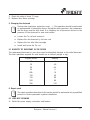
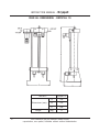
1
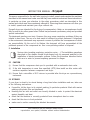
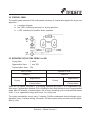
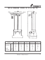
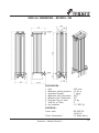
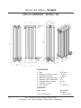
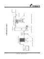
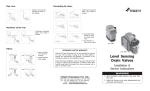
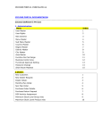
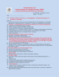
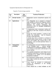
INSTALLATION
OPERATION
MAINTENANCE
Regenerative Type Heatless
Desiccant Dryer
Dryspell
WE REDEFINE COMPRESSED AIR TREATMENT SYSTEMS
Contents
1.
1.1
1.2
1.3
1.4
1.5
1.6
1.7
Introduction
Design
Relevant Units
Statement of Conformity
Description
Adsorbant Material
Operating Principles
Safety
2
2.
Installation
4
2.1
2.2
2.3
2.4
2.5
Caution
Storage
Installation Site and Connections
Electrical Connections
Running the Installation
3.
3.1
3.2
3.3
3.4
Operation
Operator
Control Panel
Operating Cycles Time
How to Stop the Dryer
6
4.
Maintenance
8
4.1
4.2
4.3
5.
Monthly Inspections
Half-yearly Inspections
Annual Inspections
Changing the desiccant
9
5.1
Quantity of Desiccant in the Dryer
6.
Repair work
6.1
6.2
6.3
6.4
6.5
6.6
6.7
7.
LED’s not Glowing
Tower Status LED not Changing
LED’s Status Changes but Tower not Switching
No Purging
Continuous Purging at Tower 1
High Purge Loss
High Pressure Drop Across Dryer
Diagrams
7.1
7.2
7.3
7.4
Operation Diagram
Overall Dimensions
How to Increase your Compressed Air Quality
Typical Layout of Compressed Air System
9
Reference : Manual Version 2
10
12
1
INSTRUCTION MANUAL -
Dryspell
READ THIS MANUAL CAREFULLY
BEFORE INSTALLING OR OPERATING THE EQUIPMENT
!
These symbols warn you of any dangers and the measures to be taken to prevent
them.
The most important points for the correct operation of your dryer are printed in bold type.
1. Introduction
Dryspell series is a heatless adsorption air dryer range especially made for small compressed
air flow treatment. Compact and easy to maintain, each dryer is equiped with a pre-filter
0.3micron to protect the dessicant from the variety of air compressed pollutant and with After
filters.
1.1 DESIGN
Dryspell heatless regenerating adsorption dryers make it possible to eliminate any water
vapour remaining in the compressed air at the outlet of the compressor + final condenser
assembly. The dryers have been designed under nominal standard conditions in order to
obtain a dew point of -40oC.
1.2 RELEVANT UNITS
This manual describes the following models :
2
Dryspell
Model
Nominal Flow cfm
10
10
20
30
20
30
45
45
60A
60
100
150
100
150
200
200
300
300
This Document may be modified without notice
reproduction, even partial, forbidden without written Authentication
1.3 STATEMENT OF CONFORMITY
The units listed above comply with the current legislation and, in particular, with the following
European directives :
l
l
l
l
97/23/CE
89/392/CEE
89/336/CEE
73/23/CEE
:
:
:
:
Pressurised Equipments
Machine Safety
Electromagnetic Compatibility
Low Voltage
1.4 DESCRIPTION
The dryer consists of :
l 2 aluminium tanks filled with desiccant
l 2 solenoid valves
l 2 exhaust silencers
l 1 regeneration nozzle
l 1 electronic control panel
l 2 aluminium blocks including air seals and non return valve
l 1 pressure gauge
l 1 sub-micron pre-filter (0.3 to 0.6 micron)
l 2 After filters
1.5 ADSORBANT MATERIAL
The desiccant takes the form of highly porous particles with surfaces which are able to retain
(adsorb) the water vapour present in the compressed air (drying phase) and restore it when
the air is at atmospheric pressure (regeneration phase). The desiccant used is activated alumina
(CD067A).
1.6 OPERATING PRINCIPLES
The two columns operate alternately in the drying and regeneration phases. Regeneration in
one tank results from the expansion to atmospheric pressure of part of the dry compressed
air in the other. The pressure reducer is responsible for this transfer. Under nominal conditions
(service pressure of 7 bars), 10% of the nominal flow is depressurised. The regeneration
phase is shorter than the drying phase in order to allow the regenerated column to return to
service pressure before a new cycle starts.
1.7 SAFETY
!
Pressurised tanks may explode if used improperly. It is therefore essential to locate
any equipment which contains one or more of such tanks in such a way that the
risks relating to incorrect use are reduced to the absolute minimum.
Reference : Manual Version 2
3
INSTRUCTION MANUAL -
Dryspell
The person responsible for the staff who is going to install, operate and maintain the machines
described in this manual must make sure that they have read and understood these instructions.
In particular we draw your attention to the safety procedures which are described in this
manual and which must be scrupulously adhered to. Observing these measures will allow you
to install, operate and maintain your dryer without risk.
Dryspell dryers are intended for the drying of compressed air. Under no circumstances should
they be used to dry other gases before Trident has performed a preliminary study and provided
special instructions.
The desiccants used are non toxic. However, they may cause respiratory problems if they are
inhaled in dust form. The use of a dust mask is sufficient to protect personnel. If dispersed
in the environment, desiccants may represent a source of pollution the consequences of which
are uncontrollable. By the end of its lifetime, the desiccant will have accumulated all the
pollutants present in the compressed air. Use a non-polluting method of disposal.
2. Installation
!
Various risks (crushing, explosion, projection, noise,…): The installation operations
described in this chapter should be performed only by personnel qualified in the
installation of electro-pneumatic systems. Follow the procedure described below
with care in order to prevent exposing personnel to danger.
2.1 CAUTION
(i)
Ensure that the compressor drain port is provided with an automatic drain valve.
(ii) If the inlet temperature is more than specified (40oC) then install an after cooler with
moisture seperator between compressor and dryer.
(iii) Ensure that a microfilter of 0.01 micron is provided after the dryer as a precautionary
instrument.
2.2 STORAGE
If your dryer is about to be stored during a long time before installation and use, take care
to the following instructions :
if possible, let the dryer in its original packing (In particular products fitted with marine
packing with plastic film and dessicant)
checking that air inlet and outlet are correctly blocked in order to protect the dessicant
against humidity and dust.
l
l
l
check that the machine is correctly protected from atmospheric dust or water.
l
check that the store is frost protected
l
make sure to archive correctly the attached documents.
4
This Document may be modified without notice
reproduction, even partial, forbidden without written Authentication
2.3 INSTALLATION SITE AND CONNECTIONS
1. Install the dryer in a closed clean, dry room protected from frost. Access to the room
should be restricted to personnel qualified in unit maintenance and operation. The room
must be adequately ventilated. The dryer must not be directly exposed to sources of heat.
The temperature of the room should not exceed 43oC.
2. Make sure that the dryer is not near any equipment which does not comply with the
electromagnetic compatibility directives and which may degrade dryer operation. There
must be a minimum distance of 1 m between the dryer and any other equipment which
uses electricity.
3. Ensure that the dryer is installed in vertical position.
4. Fix the anchor points if it's necessary.
5. Install a system of by-pass valves between the dryer inlet and outlet so as to be able to
service the installation without having to interrupt the compressed air supply from the
network (see diagram above). The upstream and downstream valves must be closed
during installation.
6. Connect the compressed air for processing to the dryer inlet (pre-filter connection) with
strain-free ducts.
7. Connect a drain pipe to the Pre-filter lower part connection (¼''F)
8. Connect the processed compressed air to the dryer output with strain-free ducts.
9. Check that all the connectors are airtight and that the fixings are tight.
Reference : Manual Version 2
5
INSTRUCTION MANUAL -
Dryspell
2.4 ELECTRICAL CONNECTIONS
Connect the electrical power cable to a 220-240 V, single phase, 50 Hz grounded power
supply. The electrical connecting is done by the DIN connector located on the front face of the
dryer.
!
Risk of electrical shock: When connecting the machine, cut off the power at the
connecting point.
2.5 RUNNING THE INSTALLATION
!
Various risks (explosion, projection, noise, ...): Do not pressurise until the installation
procedure has been completed.
The valves upstream and downstream of the dryer must be closed and the by-pass valve open
before the compressor is started.
1. Close the isolated switch located upstream of the dryer.
2. Check if the LED of the tower in drying operation glows and if the automatic drain valve
at the bottom of the prefilter drains every 4 mins.
3. Open slowly the down stream valve and check the pressure on the dryer's pressure gauge.
4. Avoid any sudden variation in pressure as this may damage the dryer.
5. Slowly open the upstream valve and check the pressure at the dryer's pressure gauge.
6. Slowly close the by-pass valve.
3. Operation
3.1 OPERATOR
Only a minimum level of experience in handling compressed air is necessary to operate a
Dryspell dryer:
6
l
Pressure and bar unit
l
Flow and m3/h unit
l
Dew points and oC unit
l
Components of a fluid network : compressor, valves, drains, taps, pressure gauges,
filters, tanks, ...
This Document may be modified without notice
reproduction, even partial, forbidden without written Authentication
3.2 CONTROL PANEL
The control panel presents all the instruments necessary to control and regulate the dryer (see
appendix) :
l
a machine diagram
two LED’s indicating the tower in drying operation.
l
a LED indicating the prefilter drain operation.
l
3.3 OPERATING CYCLES TIME FROM 5 to 300
Drying time
: 2 min’s
Regeneration time : 1 min 30s
Pressurization time : 30s
FIRST CYCLE
SECOND CYCLE
TOWER 1
TOWER 2
Regeneration
Drying
Regeneration
Drying
Pressurization
Pressurization
When DL1 is lighted, the tower 1 is in drying operation and tower 2 is in regeneration one.
After tower 2 regeneration finished, DL2 is blinking to show that the tank is now in pressurization
stage. After 30 seconds of pressurization, the air dryer operating cycle is inversed that means
tower 1 is in regeneration stage and tower 2 in drying one.
The cycles permutation occurs every 2 minutes. Prefilter condensate drain discharge is programmed every 4 minutes during 4 seconds. All these cycles times are fixed and not adjustable by user.
Reference : Manual Version 2
7
INSTRUCTION MANUAL -
Dryspell
3.4 HOW TO STOP THE DRYER
!
Various risks (projection, explosion, noise,...): Whenever working on the dryer, it
is essential to disconnect it from the network. Follow the procedure below:
1. Open the by-pass valve
2. Close the upstream valve
3. Close the downstream valve
4. Cut off and lock the isolating switch before the dryer
4. Maintenance
Adsorption dryers are robust, reliable machines. To ensure uninterrupted, problem-free operation,
regularly perform the inspections below.
4.1 MONTHLY INSPECTIONS
During the monthly routine inspection, check that :
l the drying and regeneration cycle functions normally,
l
the silencers are not clogged.
4.2 HALF-YEARLY INSPECTIONS
l
Check that the drying and regeneration cycles functions normally
l
Check to see whether the silencers are clogged
Replace the cartridge of the prefilter. Follow the following procedure:
l
1. Stop the dryer.
2. Use one hand to release the locking part and the other to turn the bottom
housing of the filter until its escape.
3. Descrew the satured filter element
4. Screw the new cartridge
5. Refit the bottom housing of the filter
6. Start the machine
4.3 ANNUAL INSPECTIONS
1. Check that the drying and regeneration cycles functions normally
2. Check to see whether the silencers are clogged
3. Replace the cartridge of the prefilter. Follow the following procedure
4. Check the state of the desiccant: if the desiccant is brown (oil pollution) or if there is a
lot of dust (disintegration), then change the desiccant (see next section).
8
This Document may be modified without notice
reproduction, even partial, forbidden without written Authentication
5. Check the state of block 'O' rings.
6. Replace after filters cartridge
5. Changing the desiccant
!
Various risks (explosion, projection, noise, ...) : This operation should be performed
by professionals of adsorption dryers. During the entire operation, the compressor
and the dryer must be shut down. It is obligatory for all personnel who are in the
presence of the desiccant to wear dust masks.
l
Loosen the Tie rod and remove it
l
Replace the old dessicant by the new one
l
Replace the two after filter cartridge
l
Install and screw the Tie rod
5.1 QUANTITY OF DESICCANT IN THE DRYER
The replacement desiccant in your dryer must be absolutely identical to the initial desiccant.
The total quantities required for each model are as follows (weight in kg) :
Dryspell model
Quantity
10
2
20
4.8
30
6.4
45
60A
9
16
100
40
150
80
200
300
80
120
6. Repair work
!
The repair operations described in this section should be performed only by qualified
persons in electro-pneumatic systems installation.
6.1 LEDS NOT GLOWING
A - Check the power supply connection and tension
Reference : Manual Version 2
9
INSTRUCTION MANUAL -
Dryspell
6.2 TOWER STATUS LED NOT CHANGING
A - Change the controller
6.3 LEDS STATUS CHANGES BUT TOWER NOT SWITCHING
A - Check coil connection at DIN and terminal connector in the controller
B - Check the solenoid valve
6.4 NO PURGING
A - Check the solenoid valve
B - Check the exhaust valve
C - Clean the silencer (muffler)
6.5 CONTINUOUS PURGING AT TOWER 1
A - Shuttle not closing
B - Check pilot air for exhaust valve alimentation
C - Check exhaust valve piston struck
6.6 HIGH PURGE LOSS
A - Check outlet shuttle closing
B - Check for silencer chock
6.7 HIGH PRESSURE DROP ACROSS DRYER
A - Pre-filter may be chocked. Check and replace filter cartridge
B - Check whether the utilisation flow is more than inlet flow as per dryer spec.
7. Diagrams
7.1 OPERATION DIAGRAM
7.2 OVERALL DIMENSIONS
10
This Document may be modified without notice
reproduction, even partial, forbidden without written Authentication
Reference : Manual Version 2
11
Part Name
Pre-filter (0.3-0.6 microns)
Pre-filter drain valve (¼” F)
Inlet shuttle valve
Solenoid valve
Exhaust silencer
Regulation (not shown)
Desiccant tower
After filter (In built)
Regeneration nozzle
Outlet shuttle valve
Rep.
1
2
3
4
5
6
7
8
9
10
1
1
2
2
1
2
2
1
1
1
Qty.
INSTRUCTION MANUAL -
Dryspell
OVER ALL DIMENSIONS - DRYSPELL 10
MODELS
Dimensions (mm)
Weight
12
Dryspell 10
A
200
B
250
C
590
(Kg)
12
This Document may be modified without notice
reproduction, even partial, forbidden without written Authentication
OVER ALL DIMENSIONS - DRYSPELL 20 / 30 / 45 / 60A / 100
MODELS
Dryspell 20
Dryspell 30
Dryspell 45
A
265
265
265
285
300
B
300
300
300
350
415
C
635
785
1035
1250
1540
Weight
(Kg)
16
28
34
43
81
Inlet/Outlet
BSP
½”
½”
½”
¾”
1”
Dimensions
Reference : Manual Version 2
Dryspell 60A Dryspell 100
13
INSTRUCTION MANUAL -
Dryspell
OVER ALL DIMENSIONS - DRYSPELL 150
SPECIFICATION :
1.
2.
3.
4.
5.
6.
7.
8.
Flow
Maximum working pressure
Operating Pressure
Maximum Inlet Temperature
Minimum Inlet Temperature
Desiccant Qty per tower
Total No. of Tower
End condition
:
:
:
:
:
:
:
:
150 scfm
16 bar g
7 bag g
45oC
3oC
15 kg
4
1½” BSP (F)
ELECTRICAL :
Power Input
Power Consumption
14
: 85-260V AC
50/60 HZ
: 12 Watts (Max.)
This Document may be modified without notice
reproduction, even partial, forbidden without written Authentication
OVER ALL DIMENSIONS - DRYSPELL 200
SPECIFICATION :
1.
2.
3.
4.
5.
6.
7.
8.
Flow
Maximum working pressure
Operating Pressure
Maximum Inlet Temperature
Minimum Inlet Temperature
Desiccant Qty per tower
Total No. of Tower
End condition
:
:
:
:
:
:
:
:
200 scfm
16 bar g
7 bag g
45oC
3oC
20 kg
4
1½” BSP (F)
ELECTRICAL :
Power Input
Power Consumption
Reference : Manual Version 2
: 85-260V AC
50/60 HZ
: 12 Watts (Max.)
15
INSTRUCTION MANUAL -
Dryspell
OVER ALL DIMENSIONS - DRYSPELL 300
SPECIFICATION :
1.
2.
3.
4.
5.
6.
7.
8.
Flow
Maximum working pressure
Operating Pressure
Maximum Inlet Temperature
Minimum Inlet Temperature
Desiccant Qty per tower
Total No. of Tower
End condition
:
:
:
:
:
:
:
:
300 scfm
16 bar g
7 bag g
45oC
3oC
20 kg
6
2” BSP (F)
ELECTRICAL :
Power Input
Power Consumption
16
: 85-260V AC
50/60 HZ
: 12 Watts (Max.)
This Document may be modified without notice
reproduction, even partial, forbidden without written Authentication
Reference : Manual Version 2
17
Level Sensing Drain Valve
Compressor
Air Cooled After Cooler
Automatic Drain Valve
Moisture
Seperator
Air Receiver
COMPRESSED AIR LAYOUT
Heatless Type Dessicant Dryer
Dryspell
Micro Filter
WARRANTY
Products of Trident Pneumatics Pvt Ltd are guaranteed to be free from
defects in materials and workmanship when installed and operated in
accordance with the instructions outlined in the Instruction Manual.
Trident Pneumatics Pvt. Ltd.'s obligation under this warranty shall be
limited to repair or replacement (at the discretion of Trident) of defective
goods returned to Trident's plant within one (1) year from the date of
commissioning or 18 months from the date of invoicing which ever is
occurring earlier.
Product
:
Model
:
Serial No.
:
Refer Name Plate
:
___________________________
Quality Assurance Dept.
Trident Pneumatics Pvt Ltd
5/232, K.N.G Pudur Road, Somayampalayam,
Coimbatore 641 108. Ph : 0422 2400492, 2401373
Fax : 0422 2401376 e-mail : [email protected]
Website : www.tridentpneumatics.com
INSTALLATION & COMMISSIONING REPORT
HEATLESS DESICCANT DRYER
Customer
:
Model
:
Sl.No
:
Contact person :
Phone
:
Designation
Fax
:
:
(Please add any comments or remarks here found while unpacking)
1. INSTALLATION
a) Installation at
: Before / After Air Receiver
LED Glowing
Yes / No
b) Inlet Air
Temperature
: Normal / High
Tower 1 and 2 Drying
Yes / No
c) Side clearance
provided
: Yes / No
Depressurizing
Yes / No
Regeneration
Yes / No
d) Power Grounded : Yes / No
e) Air Flow Outlet
: Normal / Faulty
f) Change over
sequence
: Normal / Faulty
g) Change over
sequence
: Normal / Faulty
2. COMMISSIONING
Installation
Date of completion
Commissioning
Date of completion
Comments :
Customer
Signature & Name of
installing Engineer
Installation Engineer
Dealers
Signature & Seal
Customer's
Signature & Seal
Compressed Air Quality can be maximized through
Application : Power Coating & Spray Painting
Application : Cement Plant
Flow Taken : Example 20 cfm
Flow Taken : Example 45 cfm
Location
Location
Product
Product
Condensate Drain Ports LDV 1000 / Equivalent
Condensate Drain Ports LDV 1000 / Equivalent
After the dryer
G 100 Y / Equivalent
Before the dryer
G 100 P / Equivalent
Desiccant Dryers
Dryspell 20 / Equivalent
After the dryer
G 100 Y / Equivalent
Desiccant Dryers
Dryspell 45 / Equivalent
Application : Food Pharma & Hospital
Flow Taken : Example 10 cfm
Location
Application : Process & Chemical Industry
Flow Taken : Example 45 cfm
Product
Condensate Drain Ports LDV 1000 / Equivalent
Before the dryer
G 24 P / Equivalent
After the dryer
G 24 Y / Equivalent
Desiccant Dryers
Dryspell 10 / Equivalent
Application : Instrumentation
Location
Product
Condensate Drain Ports LDV 1000 / Equivalent
Before the dryer
G 100 P / Equivalent
After the dryer
G 100 Y / Equivalent
Desiccant Dryers
Dryspell 45 / Equivalent
Application : Packing M/c
Flow Taken : Example 10 cfm
Flow Taken : Example 20 cfm
Location
Location
Product
Product
Condensate Drain Ports LDV 1000 / Equivalent
Condensate Drain Ports LDV 1000 / Equivalent
Before the dryer
G 24 P / Equivalent
After the dryer
G 100 Y / Equivalent
After the dryer
G 24 Y / Equivalent
Desiccant Dryers
Dryspell 20 / Equivalent
Desiccant Dryers
Dryspell 10 / Equivalent
Application : Process & Chemical Industry
Application : Engineering Industry
Flow Taken : Example 45 cfm
Flow Taken : Example 30 cfm
Location
Location
Condensate Drain Ports LDV 1000 / Equivalent
Product
Condensate Drain Ports LDV 1000 / Equivalent
Before the dryer
G 100 P / Equivalent
After the dryer
G 100 Y / Equivalent
Desiccant Dryers
Dryspell 30 / Equivalent
Before the dryer
G 100 P / Equivalent
After the dryer
G 100 Y / Equivalent
Desiccant Dryers
Dryspell 45 / Equivalent
Application : Printing Industry
Flow Taken : Example 45 cfm
Application : CNC M/C
Location
Flow Taken : 20 cfm
Model Name
Product
Product
Condensate Drain Ports LDV 1000 / Equivalent
Model Code
Before the dryer
G 100 P / Equivalent
Condensate Drain Ports LDV 1000 / Equivalent
After the dryer
G 100 Y / Equivalent
Desiccant Dryers
Desiccant Dryers
Dryspell 45 / Equivalent
Dryspell 20 / Equivalent
Reference : Manual Version 2