1
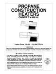
Chapter
4
Preparing The Printer For Maintenance
Preparing The Printer For Maintenance
WARNING
Unplug the printer power cord from the printer or power outlet before
you do any maintenance procedure. Failure to remove power could
result in injury to you or damage to equipment. If you must apply power
during maintenance, you will be instructed to do so in the maintenance
procedure.
IMPORTANT
Do not attempt field repairs of electronic components or assemblies. Do
not de-solder any circuit board components. Replace a malfunctioning
electronic assembly with an operational spare. Most electronic
problems are corrected by replacing the printed circuit board assembly,
sensor, or cable that causes the fault indication. The same is true of
failures traced to the hammer bank: replace the entire shuttle frame
assembly. It is not field repairable. Hammer spring assemblies are the
only replaceable components of the shuttle frame assembly.
To prepare the printer for maintenance, do the following steps before you
make any adjustments:
1. Set the printer power switch to O (off).
2. Unplug the printer power cord from the printer or AC power source.
3. Disconnect the data (signal) cable from the printer interface.
4. Open the printer cover.
5. Unload paper.
6. Remove the ribbon.
7. Read the entire maintenance procedure before you begin working on the
printer.
8. Gather the necessary parts before you begin working on the printer.
132
Cover Assembly, Top, Pedestal Models
Cover Assembly, Top, Pedestal Models
Removal
1. Prepare the printer for maintenance (page 132).
2. Loosen—do not remove—the two #2 Phillips hold-down screws on the
rear of the printer. (See page 228, item 5.)
3. Open the printer cover.
4. Loosen the four captive #1 Phillips screws until the control panel is
released from the printer top cover assembly. (See page 228, items 1 and
2.) Set the control panel assembly on the shuttle cover assembly.
5. Loosen the two captive #2 Phillips screws in the lower front corners of the
top cover. (See page 228, item 3.)
6. Lift the top cover assembly off the printer base.
Installation
1. Reverse steps 2 through 6 of the removal procedure.
2. Return the printer to normal operation (page 133).
179
Chapter
5
Section II: Illustrated Parts Lists
4
10
2
1
9
11
5
14
3
13
6
7
12
8
Figure 35. Pedestal Details
228
Paper Path
Paper Path
NOTE: This procedure applies only to cabinet models.
Removal
1. Prepare the printer for maintenance (page 132).
2. Loosen the three screws that secure the paper path to the card cage.
(See Figure 27.)
3. Slide the paper path to the left and lift it off the card cage.
Installation
1. Position the paper path offset slightly to the left on the card cage with the
keyway cutouts over the three loosened screws. (See Figure 27.)
2. Slide the paper path to the right, engaging the three screws in the keyway
slots. Slide the paper path to the right as far as it will go.
3. Tighten the screws securing the paper path to the card cage. (See Figure
27.)
4. Return the printer to normal operation (page 133).
Paper Path
Screw
Screw
Figure 27. The Paper Path
199
Chapter
5
Section I: Replacement Procedures
Cover Assembly, Shuttle
Removal
1. Prepare the printer for maintenance (page 132).
2. Loosen the shuttle cover screws (page 230, item 2).
3. Grasping the edges of the shuttle cover assembly, tilt the rear edge up
and lift the shuttle cover assembly out of the printer.
Installation
1. Place the shuttle cover assembly in the printer. Tilt the forward edge of
the cover down slightly and work the cover into position.
NOTE: Make sure the holes in the cover are over the locating pins on the
base casting.
2. Tighten the shuttle cover screws (page 230, item 2).
3. Return the printer to normal operation (page 133).
178
Chapter
5
Section II: Illustrated Parts Lists
5
6
10
4
9
3
12
11
2
1
8
7
Figure 36. Inside Covers, Cabinet Models
230
Shuttle Frame Assembly
Shuttle Frame Assembly
Removal
1. Prepare the printer for maintenance (page 132).
2. Remove the shuttle cover assembly (page 178).
3. Disconnect the MPU cable connector P03 and shuttle motor cable
connector P02 (page 238, items 5 and 6).
CAUTION
To prevent electrostatic damage to electronic components, always wear
a properly grounded static wrist strap when you handle the shuttle
frame assembly.
4. Disconnect the hammer drive and hammer logic cable connectors from
the terminator board on the shuttle frame assembly. (See page 236.)
5. Loosen the side 5/32 inch socket head clamp screws on each end of the
shuttle and pull the clamps back and off the guide shaft. Do not remove
the clamps. Hand tighten the clamp screws to hold the clamps back.
6. Loosen the center 5/32 inch socket head screw enough to release the
shuttle frame assembly from the base casting.
7. Unlock and slide the tractors outward as far as they will go on the tractor
support shaft.
8. Open the forms thickness lever all the way.
9. Grasp the support legs cast on both sides of the shuttle motor and lift the
shuttle frame assembly out of the base casting. Lift it slowly and carefully:
the shuttle frame assembly is heavy.
215
Chapter
5
Section I: Replacement Procedures
Installation
1. Install the hammer bank / ribbon mask cover assembly if it was removed
(page 177).
CAUTION
To prevent electrostatic damage to electronic components, wear a
properly grounded static wrist strap when you handle the shuttle frame
assembly.
DO NOT remove the grease from the shaft of the replacement shuttle
frame assembly. The shuttle shaft is aluminum, and the clamped ends of
the shaft must be greased to prevent galling.
2. Open the forms thickness lever and move the tractors as far left and right
as possible.
3. Holding the shuttle frame assembly by the support legs located on both
sides of the shuttle motor and set it into the base casting (page 236). Use
both hands: the shuttle frame assembly is heavy.
4. Align the center 5/32 inch socket head screw in the base casting and
hand turn the screw until only two or three threads have started.
5. Pull the shuttle frame assembly toward the front of the printer and hold it
in this position while you do step 6.
CAUTION
Do not over-tighten the shuttle frame assembly clamp screws.
6. Slide each side clamp over the guide shaft and torque the 5/32 inch
socket head clamp screw to 20 ± 2 inch-pounds (2.26 ± 0.23 N•m).
7. Torque the center captive 5/32 inch socket head screw to
20 ± 2 inch-pounds (2.26 ± 0.23 N•m).
8. Connect the hammer drive and hammer logic cable connectors to the
terminator board on the shuttle frame assembly.
9. Connect the shuttle motor cable connector. (See page 238, item 6.)
10. Route the MPU cable under the extension spring and connect the MPU
cable connector. (See page 238, item 5.) After the MPU cable is
connected make sure that it does not touch the extension spring.
11. If the shuttle assembly is a new or refurbished unit, adjust the platen gap
(page 140); otherwise, skip to step 12.
12. Install the shuttle cover assembly (page 178).
13. Adjust the hammer phasing (page 148).
14. Return the printer to normal operation (page 133).
216
Chapter
5
Section II: Illustrated Parts Lists
Two places:
Exploded to show
assembly. Do not
remove the
holddown clamps
and screws.
14
1
3
To J02
(Shuttle
Motor) To J03
(MPU)
15
5
2
8
9
22
7
4
10
15
16
12
11
15
6
13
17
18
To Terminator
Board on Shuttle
Frame
Figure 39. Print Mechanism and Circuit Boards
236
Chapter
5
Section II: Illustrated Parts Lists
3
Spring Lug (Do not
remove grease)
4
Spring Lug (Do not
remove grease)
A
1
2
6
CAUTION:
Make sure the MPU
cable does not touch
the extension spring
after cable
connection.
5
0.010 ± .001 inch (0.254 ± .025 mm)
A
Figure 40. Magnetic Pickup (MPU) and Extension Spring
238
Cover Assembly, Hammer Bank / Ribbon Mask
Cover Assembly, Hammer Bank / Ribbon Mask
Removal
1. Prepare the printer for maintenance (page 132).
2. Remove the shuttle frame assembly (page 215).
3. Lift the thick plate of the hammer bank cover assembly at one end, and
peel the cover away from hammer bank magnets. (See Figure 23.)
Installation
CAUTION
The hammer bank contains a strong magnet. To prevent damage to the
hammer tips, do not let the steel hammer bank cover assembly of early
models snap into place as the hammer bank magnet attracts it. Any
impact of the cover against the hammer bank can break hammer tips.
1. With the thick plate facing the hammer bank, hold the hammer bank cover
assembly at a slight angle and engage the bottom edge on the alignment
pins. First engage the center (round) hole, then the left (oblong) hole, to
ensure that the cover lies flat on the hammer bank. (See Figure 23.)
2. Gently lower the hammer bank cover assembly until it lies flush on the
hammer bank.
3. Check that the hammer bank cover assembly is positioned over the
alignment pins and the hammer tips.
4. Install the shuttle frame assembly (page 215).
5. Return the printer to normal operation (page 133).
Oblong Hole
Hammer Bank
Cover Assembly
Round Hole
Alignment Pin
Figure 23. Hammer Bank Cover Assembly
177
Hammer Spring Assembly
Hammer Spring Assembly
Removal
1. Prepare the printer for maintenance (page 132).
2. Remove the shuttle frame assembly (page 215).
3. Carefully vacuum the shuttle frame assembly.
4. Remove the hammer bank cover assembly (page 177).
CAUTION
Hammer springs and hammer tips are fragile. Do not touch the hammer
springs or tips. Handle hammer spring assemblies by the thick
mounting base only. Apply pressure only to the mounting base.
5. Remove the mounting screws from the old hammer spring assembly.
(See Figure 24.)
6. Handling the hammer spring assembly by the mounting base only, gently
push up the mounting base and pry the old spring assembly off its
mounting pins. (See Figure 24.)
7. Inspect the hammer bank and the old hammer spring assembly:
a. If there is ink on the hammer bank mounting surface, the hammer
spring assembly mounting surface, or the hammer spring neck or
tines, reinstall the old hammer spring assembly and replace the
shuttle frame assembly (page 215).
b. If the old hammer spring assembly and the hammer bank are free of
ink, install the new hammer spring assembly, as shown in the next
section.
NOTE: The hammer spring assemblies
shown here are for a P5015 printer.
Although hammer spring assemblies
vary in appearance and number of
mounting screws, removal and
installation are the same for all models.
Discard old screws.
Figure 24. Hammer Spring Assembly, Removal
185
Chapter
5
Section I: Replacement Procedures
Installation
1. Using a clean dry cloth, wipe the hammer spring mounting surface on the
hammer bank. Make sure the cloth does not leave lint on the hammer
bank.
CAUTION
Hammer springs and hammer tips are fragile. Do not touch the hammer
springs or tips. Handle hammer springs by the thick mounting base
only. Apply pressure only to the mounting base.
2. Handling the hammer spring assembly by the mounting base only,
remove the new assembly and mounting screws from the box.
3. Handling the hammer spring assembly by the mounting base only,
carefully position it on the hammer bank mounting pins. then gently press
the mounting base down against the alignment pins. (See Figure 25,
page 187.)
4. Continue pressing down on the mounting base of the the new hammer
spring assembly as you install the mounting screws from the replacement
kit. Using a Torx T-10 bit adapter, torque each screw to 14 inch-pounds
(1.58 N•m). Tighten the center screw(s) first. (See Figure 25, page 187.)
5. Install the hammer bank cover assembly (page 177).
6. Install the shuttle frame assembly (page 215).
7. Install the ribbon and load paper.
CAUTION
Do not attempt to adjust or “tweak” hammer springs.
8. Run a Diagnostic Printer Test and check print quality (page 114):
a. If print quality is acceptable, return the printer to normal operation
(page 133).
b. If print quality is still degraded, replace the shuttle frame assembly
(page 215).
186
Hammer Spring Assembly
NOTE: The hammer spring assembly
shown here is for a P5015 printer.
Although hammer spring assemblies
vary in appearance and number of
mounting screws, removal and
installation are the same for all models.
Gently press down on the mounting
base and hold the hammer spring in
position as you install the screws.
Use new screws from the kit.
Torque the screws to 14 inchpounds (1.58 Newton-meters).
New Hammer
Spring Assembly
Figure 25. Hammer Spring Assembly, Installation
187
Chapter
4
Platen Gap Adjustment
Platen Gap Adjustment
IMPORTANT
Only do this procedure if the original equipment shuttle frame assembly
or platen has been replaced by a new or refurbished unit.
1. Prepare the printer for maintenance (page 132).
2. Remove the shuttle cover assembly (page 178).
3. Loosen the platen open belt (page 136, steps 2, 3, and 4).
4. Raise the forms thickness lever (1) to the fully open position.
CAUTION
Do not force the platen against the feeler gauge and do not move the
feeler gauge laterally across the hammer bank. Damage to the hammer
tips will result.
5. Insert a 0.011 inch (0.28 mm) flat feeler gauge (2) straight down between
the hammer bank cover plate (3) and ribbon mask (4), within four hammer
positions of the left end of the hammer bank.
CAUTION
Adjust the platen setscrews less than 1/4 turn on one side, then check
the other side. Adjustment sensitivity is approximately 0.03 inch per
revolution of the setscrew. Also, insert the feeler gauge no more than 2
inches down from the top of the ribbon mask.
6. Gently close the forms thickness lever (1) all the way. As the platen is
closing, gently slide the feeler gauge up and down, keeping it between the
hammer tip and ribbon mask. If the feel is too tight when the platen is
being closed, adjust the 3/32 inch setscrew (5) at the end of the platen
counterclockwise. If the feel is too loose, adjust the setscrew clockwise.
With the forms thickness lever closed all the way, the feeler gauge should
contact both the tips and the ribbon mask and move with light friction.
Shift the gauge slightly to verify.
7. Repeat steps 4 through 6 at the right end of the hammer bank.
8. After adjusting both sides, check the gap again at both ends. Readjust if
necessary.
NOTE: Gap widths other than 0.011 inch (0.28 mm) in the middle/inner
sections of the platen are okay, provided the gap at each end of the
platen is 0.011 inch (0.28 mm).
9. When the platen gap is correct at both ends of the platen, adjust the
platen open belt (page 136).
10. Install the shuttle cover assembly (page 178).
11. Check the hammer phasing adjustment (page 148).
12. Return the printer to normal operation (page 133).
140
Adjustments and Tests
A
1
NOTE: Left side adjustment
shown. Right side is the same.
5
2
3
4
A
Legend:
1)
2)
3)
4)
5)
Forms Thickness Lever
Feeler Gauge
Hammer Bank Cover
Ribbon Mask
Setscrew, 3/32 inch hex (2)
Figure 13. Platen Gap Adjustment
141
Chapter
4
Belt, Platen Open, Adjustment
Belt, Platen Open, Adjustment
1. Prepare the printer for maintenance (page 132).
2. Cabinet Models: Remove the paper path (page 199).
Pedestal Models: Remove the top cover assembly (page 179).
3. Remove the platen open belt cover (1) by squeezing the top and bottom
to release the plastic tabs from the slots in the side plate.
4. Using a 5/32 inch Allen wrench, slowly loosen the motor adjustment
screw (2) just enough to permit movement of the platen open motor in the
slotted side plate.
5. Close the forms thickness lever all the way.
CAUTION
Too much tension on the platen open belt can cause the platen gap to
change, which can lead to premature wear of the platen, damaged
hammer tips, and poor print quality.
6. The spring will automatically tension the belt.
7. Slowly tighten the motor adjustment screw (2).
NOTE: Belt tension is correct if the belt deflects 3/16 inch midway between
the pulleys. If deflection is more or less than 3/16 inch, repeat steps 4
through 7.
8. Snap the platen open belt cover (1) into the slots in the side plate.
9. Cabinet Models: Install the paper path (page 199).
Pedestal Models: Install the top cover assembly (page 179).
10. Return the printer to normal operation (page 133).
136
Adjustments and Tests
A
3/16 inch
2
A
3
1
2
Legend:
1)
2)
3)
Belt Cover
Motor Mount Screw (2)
Platen Open Motor Shaft
Figure 11. Platen Open Belt Adjustment
137
Chapter
4
Coil Temperature Adjustment
Coil Temperature Adjustment
This procedure applies only to 1500 lpm printers.
Do this procedure only when the original CMX controller board or shuttle
frame assembly have been replaced or you are instructed to do so in a
troubleshooting procedure. Do not do this procedure if the original CMX
board or shuttle frame assembly were removed and reinstalled as part of
other maintenance tasks.
IMPORTANT
The shuttle frame assembly must be at room temperature to do this
procedure. If the shuttle was run prior to this procedure, allow it to cool
for 1 to 2 hours before doing this procedure.
1. Plug the AC power cord into the printer and the power source.
2. Power on the printer.
3. The printer must be offline to do this procedure. If the printer is online,
press the ON LINE key. “OFFLINE / CONFIG. CONTROL” will display.
4. Raise the printer cover.
5. On the control panel, press the = + > keys to unlock the ENTER key.
“ENTER SWITCH UNLOCKED” briefly displays. (If “LOCKED” displays,
simply press = and > again. This is the default key combination. The lock/
unlock key combination can be programmed by the user. If = + > does
not unlock ENTER, get the combination from the user.)
6. Press = + > + < + ; to enter the factory menu. (Press all four keys at the
same time.) “Factory / Set Coil Temp” appears on the display.
7. Press ENTER. The display tells you to “PLEASE WAIT” while the coil
temperature is set by an automatic calibration sequence in printer
software.
8. When the display again reads “Factory / Set Coil Temp” press = + > to
lock the ENTER key.
9. Press the ON LINE key to exit the Factory menu.
10. Coil temperature is now set. Power off the printer and close the printer
cover.
11. Return the printer to normal operation (page 133).
156
Chapter
4
Hammer Phasing Adjustment
Hammer Phasing Adjustment
You must check and adjust hammer phasing if the controller board is
replaced, the shuttle frame assembly is removed, or if the MPU is replaced.
The hammer phase value is a timing parameter that permits you to adjust the
vertical alignment of dots in character printing. The phase value numerical
units are relative; they do not represent a physical measurement or value.
Thus there is no “correct” value or range. But, if the phasing value is far
enough from the theoretical ideal value on a particular printer, errors can
occur. If, for example, you are adjusting phasing and an error such as PAP
FIFO UNDRFL* occurs, the phase value may be too high. Try a lower value.
The factory prints the initial phase value on the shuttle assembly casting, next
to the motor housing. Adjust the phasing to this value and recheck the vertical
alignment. When vertical alignment is acceptable, write the new phasing
value on the shuttle.
Phasing should be adjusted with the printer printing at full paper width.
IMPORTANT
The printer must be printing the Phase pattern of “H’s” when the
Phasing Value is changed, or the New Phasing Value will not be written
into NVRAM. If the value is changed when not printing, the printer will
return to its default phasing value when powered off then back on.
1. Raise the printer cover.
2. Install the ribbon.
3. Load full width (136 column) paper and set the top of form.
4. Power on the printer.
5. If the printer is on-line, press the ON LINE key to place the printer off-line.
“OFFLINE / CONFIG. CONTROL.” displays.
6. On the control panel, press the = + > keys to unlock the ENTER key.
“ENTER SWITCH UNLOCKED” briefly displays. (If “LOCKED” displays,
simply press = and > again. This is the default key combination. The lock/
unlock key combination can be programmed by the user. If = + > does
not unlock ENTER, get the combination from the user.)
7. Press the ; key. “OFFLINE / DIAGNOSTICS” displays.
8. Press >. “DIAGNOSTICS / Printer Tests” displays.
9. Press >. “Printer Tests / Shift Recycle” displays.
10. Press ; until “Printer Tests / Phase Printer” displays.
11. Press ENTER. The display shows “Printer Tests / Phase Printer” and the
test begins. The current phasing value is printed on the left of the printed
pattern of all H’s. As the pattern prints, compare the H’s to the figure
below. If the phasing needs adjustment, go to step 12. If the phasing is
OK, go to step 15.
148
Adjustments and Tests
Needs
Adjustment
Correct
Needs
Adjustment
12. Press >: The current phase index displays. Press > again: An asterisk (*)
appears next to the phase value.
13. Press < to increase or ; to decrease the phasing index value, then press
ENTER to activate the value as it prints. Continue to increase or decrease
the phasing index until the pattern of H’s is acceptable.
14. Press = twice: “Printer Tests / Phase Printer” displays.
15. Press ENTER to stop the test.
16. Press CLEAR. “OFFLINE / CONFIG. CONTROL” displays.
17. Press = + > (or the key combination set by the user). “ENTER SWITCH
LOCKED” briefly displays.
18. Close the printer cover.
19. Press the ON LINE key to place the printer on-line.
NOTE: If you changed the phasing value, power down the printer, remove
the shuttle cover, and write the new phase value on the aluminum
shuttle casting.
149
Adjustments and Tests
Returning The Printer To Normal Operation
When you are finished servicing the printer, test its operation and return it to
service by doing the following steps:
1. Install the ribbon.
2. Load paper.
3. Connect the data (signal) cable to the printer interface.
4. Plug the AC power cord into the printer and the power source.
5. Close the cabinet doors.
6. Set the printer power switch to | (on).
7. Test printer operation by selecting and running one of the operator print
tests. (See page 114.)
8. Select the emulation. (Refer to the User’s Manual.)
9. Set the top-of-form. (Refer to the User’s Manual.)
10. Close the printer cover.
133