1
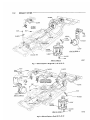
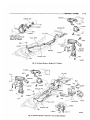
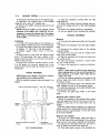
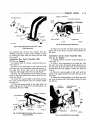
'GROUP
11
EXHAUST SYSTEM
CONTINTS
DESCRIPTION . . . . . . . . . . . . . . . . .
SERVICE DIAGNOSIS
Page
Page
1
1
SERVICE PROCEDURES . . . . . . . .
1
TIGHTENING REFERENCE . In Rear of the Manual
..
Description
Long life aluminized and stainless steel muffler
components are used on all models. Mufflers on AC-1,
AC-2 and AC-3 models are supported at the rear by
double strap hangers. " L " type hangers are used to
support the tail pipes on all models (Figs. 1, 2, 3 and
4).
Ball joint connections which allow more accurate
alignment of the exhaust system are located i n the
exhaust pipes forward of the mufflers on all models.
(Figs. 1, 2, 3 and 4).
The exhaust manifolds on all engines incorporate
a thermostatic heat control valve to direct the exhaust gases to a heat chamber beneath the carburetor
mounting flange to help vaporize the fuel. The heat
control valve is located i n the right hand manifold
(Figs. 6 and 7).
SERVIC1 D I A G N O S I S
Condition
Correction
Possible C a u s e
EXHAUST SYSTEM
EXCESSIVE EXHAUST
NOISE
(a) Leaks a t the pipe joints.
( a ) Tighten the clamps a t the leaking joints.
(b) Burned or blown out muffler.
(b) Replace the muffler assembly.
(c) Burned or rusted out exhaust pipe.
(c) Replace the exhaust pipe.
(d) Exhaust pipe leaking a t the manifold flange.
(d) Install a new gasket a n d tighten the exhaust
(e) Exhaust manifold c r a c k e d or broken.
(e) Replace the manifold.
(f)
(f) Tighten the manifold to cylinder block nuts to
pipe flange nuts to specifications.
Leak between the manifold a n d cylinder block.
specifications.
LEAKING EXHAUST
GASES
(a) Leaks a t the pipe joints.
( a ) Tighten the clamps a t the leaking joints.
(b) D a m a g e d or improperly installed gaskets.
(b) Replace gaskets as necessary.
(c) Restriction in muffler or tail pipe.
(c) Remove the restriction, if possible or replace a s
necessary.
ENGINE HARD TO
(a) Heat control valve frozen in the open position.
(a) Free up the manifold heat control v a l v e solvent number, 1879318.
W A R M UP O R WILL
NOT RETURN TO
NORMAL IDLE
NOISE IN MANIFOLD
MANIFOLD HEAT
CONTROL VALVE
RATTLE
(a) Thermostat broken.
( a ) Replace the thermostat.
(b) W e a k or broken anti-rattle spring.
(b) Replace the spring.
(a) Thermostat broken.
( a ) Replace the thermostat.
(b) Broken, w e a k or missing anti-rattle spring.
(b) Replace the spring.
SERVICE PROCEDURES
EXHAUST PIPES, MUFFLERS, TAIL PIPES
Removal
(1) Raise the vehicle on a hoist and lubricate the
clamp nuts and bolts with penetrating oil to loosen
the rust and dirt.
(2) Remove the clamps from the exhaust pipes,
mufflers and tail pipes.
11-2
EXHAUST SYSTEM
VIEW IN CIRCLE B
Fig. 1—Exhaust
System—Single
Fig. 2—Exhaust
( A C - J , AC-2, A C - 3 )
System—Dual
(M-2,
AC-3)
NK947
EXHAUST
F i g . 3 — E x h a u s t System—Single
fig,
4—Exhaust
System—Dual
(AY-1
(AY-1 Convertible
Sedan)
Models)
SYSTEM
11-3
11-4
EXHAUST SYSTEM
(3) Disconnect the ball joints in the exhaust pipes.
(4) Disconnect the exhaust pipe at the exhaust
manifolds and remove the exhaust pipe.
(5) Remove the muffler, extension pipe and the tail
pipe assembly.
NOTE; If only the muffler is to he replaced, cut the
extension at the muffler with a hack saw. If is unnecessary to remove the exhaust pipe. The replacement muffler is installed using a clamp at the front
of the muffler.
(1) Clean the manifold in solvent. Blow dry with
compressed air.
(2) Inspect the exhaust crossover passage and pressure test for leakage into any of the intake passages
(Fig. 5).
(3) Inspect the mating surfaces for parallelism.
(4) Use new gaskets when installing the manifold.
EXHAUST MANIFOLD
Removal
Installation
(1) Connect the exhaust pipes to the manifolds, using new gaskets. Tighten the nuts to 40 foot-pounds.
(2) Adjust the hanger heights for proper alignment.
(3) Tighten " U " bolt nuts to 100 inch-pounds.
(4) Tighten support clamp screws to 95 inchpounds.
(5) Align system at ball joints and tighten flange
bolts to 20 foot-pounds. The inner surfaces of the
flanges should be parallel to each other and perpendicular to the pipe axis.
(6) Adjust the converter housing bracket, so that
it is flat against the converter housing and in the
proper contact with the pipe tab. Tighten screw to 15
foot-pounds.
INTAKE MANIFOLD
NOTE; Refer to the "Engine" Group 9 for removal
and installation of the intake manifold.
With the manifold removed clean and inspect it as
follows:
(1) Disconnect the spark plug cables from the spark
plugs.
(2) Remove the alternator from the right cylinder
head.
(3) Disconnect the exhaust pipes at the exhaust
manifold flanges.
(4) Remove the nuts that hold the exhaust manifolds to the cylinder heads.
(5) Slide the manifolds off the studs and away from
the cylinder heads.
(6) Clean the exhaust manifolds in solvent. Blow
dry with compressed air.
(7) Inspect the manifolds for cracks and distortion.
Installation
NOTE: If studs came out with the nuts, install new
studs, applying sealer on the coarse thread ends. If
this precaution is not taken, water leaks may develop at the studs.
(1) Place the exhaust manifolds on the studs on the
cylinder heads and install the nuts. Tighten to 30
foot-pounds torque.
(2) Connect the exhaust pipes at the exhaust manifolds. Tighten the nuts to 40 foot-pounds torque.
(3) Install the alternator on the right cylinder head
and adjust the belt tension.
(4) Connect the spark plug cables to the spark
plugs.
Manifold
Heat Control
Valve
Inspect the operation of the manifold heat control
valve and apply Heat Control Valve Solvent, Part No.
1879318 to both ends of the valve shaft every six
months.
With the engine idling, accelerate the engine and
release quickly. The counterweight should respond by
moving clockwise approximately Vfe inch and return
to its normal position.
Removal
NY843
M O U N T I N G FLANGE
Fig. 5—Intake
Manifold
(All
Models)
(1) Loosen the counterweight clamp bolt (Figs. 6
and 7) and remove the counterweight, lock and stop
from the end of the shaft, exposing the thermostat.
(2) Unhook the thermostat from the pin and remove by sliding out of the valve shaft slot.
(3) If the valve shaft is frozen in the manifold, ap-
EXHAUST SYSTEM
11-5
EXHAUST M A N I F O L D
INSTALLED P O S I T I O N
VALVE
KR235B
Fig. 8—Positioning
Fig. 6—Manifold
Heat
Outlet
Control
Manifold
ply manifold heat control valve solvent, Part No.
1879318, and allow to stand several minutes. Loosen
by rotating the shaft back and forth until the shaft
turns easily.
Installation
413
Cu. In
Rear
Outlet
Manifold
the
Thermostat
Valve—Rear
(383,
Engines)
(1) Position shaft in extreme counterclockwise position (Fig. 6).
(2) Place a new thermostat in the shaft slot with
the outer end of the thermostat facing downward on
the right side. Wrap outer end of the thermostat
clockwise and engage under the stop pin (Fig. 6).
(3) Place the counterweight on the shaft with the
shield in the upper position and insert the lock in the
shaft slot (Fig. 6).
(4) Center the counterweight on the shaft and turn
the valve counterclockwise until the bumper passes
the stop pin.
(5) Press the counterweight on the shaft until it is
seated. Tighten the clamp bolt to 50 inch-pounds, using Torque Wrench C-3380.
(6) Make sure that the anti-rattle spring on the opposite end of the shaft is in place. Test operation of
the valve.
Installation—Center
Outlet
413 Cu. In. Engine)
Manifold
1383,
(1) Position shaft in extreme counterclockwise position (Fig. 7).
(2) Place a new thermostat in the shaft slot with
the outer end of the thermostat facing downward on
the left side. Wrap the outer end of the thermostat
counterclockwise and engage it under the stop pin
(Fig. 8).
(3) Place the counterweight on the shaft with the
shield in the upper position and insert the lock in the
shaft slot.
(4) Center the counterweight on the shaft and turn
the valve clockwise until the bumper passes the stop
pin (Fig. 9).
Jf
,
THERMOSTAT
C L A M P BOLT
KR236A
Fig. 7—Manifold
Heat
Outlet
Control
Manifold
Valve—Center
Fig. 9—Installing
the
Counterweight
11-6
EXHAUST SYSTEM
(5) Press the counterweight on the shaft until it is
seated. Tighten clamp bolt to 50 inch-pounds, using
Tool C-3380 Torque Wrench.
(6) Make sure the anti-rattle spring on the opposite
end of the shaft is in place. Test operation of the
valve.
(1) Remove the alternator.
(2) Remove the exhaust pipe from the manifold.
(3) Remove the exhaust manifold from the engine.
(4) Remove the counterweight, thermostat, shaft,
clips and anti-rattle spring.
(5) Cut the valve plate off of the shaft.
(6) Remove the shaft and press the bushings from
the manifold.
to turn freely, it will be necessary to hone the bushings.
(3) Pull the shaft out far enough to position the
valve plate on the shaft, then slide shaft into position
in both bushings.
(4) Align the hole in the valve plate with the hole
in the shaft and insert a drift into both holes to maintain correct positioning of the valve plate as it is being welded to the shaft.
(5) Remove the drift from the valve plate and
shaft.
(6) Install the new anti-rattle spring, shaft clips,
thermostat and counterweight assembly on the shaft.
(7) Install the manifold on the engine assembly.
(8) Using a new gasket, connect the exhaust pipe to
the manifold.
(9) Install the alternator and adjust the belt tension.
(10) Start the engine and test the operation of the
manifold heat control valve assembly.
Installation
Servicing
(1) Install the new bushings in the exhaust manifold.
(2) Position the shaft into both bushings and check
the shaft for freedom of turning. Should the shaft fail
Test the manifold heat control valve for proper operation during engine tune-up and apply Manifold
Heat Control Valve Solvent, Part No. 1879318, to
both ends of valve shaft.
MANIFOLD HEAT CONTROL V A L V E
REPLACEMENT
Removal