1
CAUTION:
For proper operation, ensure that the 2552-A is not subjected to large temperature gradients
during operation.
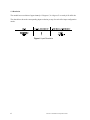
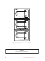
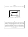
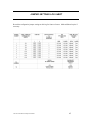
Figure 11 Wiring Diagram for Millivolt Measurements
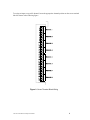
NOTE:
If a separate shield is used for RTD or Millivolt measurements it should be terminated at screw
position #2 of each channel group. The shielding for the cable should always be terminated at
the Model 2552-A. Each isolated input channel contains its own local ground for the shield
wire. The input isolation amplifier is designed in this manner by the manufacturer. Standard
practices usually require that all shields be tied together and grounded at a single point. In an
isolated system this will actually impede the system to reject noise. The correct method for
terminating the shields on an isolated channel is to connect them to the channel's local ground.
This will provide the best performance. There should never be any shield termination at the
source end of the signal wire.
CTI 2552-A Installation and Operation Guide
11