1
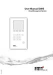
FLEX-6000 SIGNATURE SERIES
SMARTSDR SOFTWARE USER MANUAL
Version 1.3.0
08/15/2014
Copyright 2014 FlexRadio Systems. All Rights Reserved. FlexRadio Systems is a registered trademark and SmartSDR is a
trademark of FlexRadio Systems. All other brands or names are trademarks of their respective owners.
FLEX-6000 Signature Series - SmartSDR for Windows Software User’s Guide
VERSION HISTORY
Version
#
Implemented
By
Revision
Date
Approved
By
Approval
Date
Reason
1.0
1.01
Matt Youngblood
Greg Jurrens
09/30/2013
10/1/2013
Lori Hicks
Tim Ellison
9/30/2013
10/1/2013
1.03
1.05
1.0.24
1.1
1.1.3
Matt Youngblood
Greg Jurrens
Matt Youngblood
Matt Youngblood
Matt Youngblood
12/3/2013
12/3/2013
12/20/2013
1/17/2014
2/19/2014
1.1.4
Stephen Hicks
3/30/2014
1.1.5
Stephen Hicks
3/31/2014
1.1.6
Stephen Hicks
4/19/2014
1.2
Matt Youngblood
4/25/2014
1.2.1
1.2.1
1.2.16
1.2.17
1.3
Tim Ellison
Matt Youngblood
Tim Ellison
Matt Youngblood
Tim Ellison
4/30/2014
5/8/2014
6/25/2014
7/1/2014
8/15/2014
Original Draft
Minor Edits, Copyrights,
Name change
Added Features
Title-Header Edits
DAX Functionality
DAX IQ, FlexControl
Tune Step, Radio
Identification, Weighted
Averaging
Introductory text, DAX
functionality
Add notes about
preamplifier use
Add functionality from
SmartSDR v1.2
Updated screen shots
and added features for
1.2
Additional edits for v1.2
Added Tempest Changes
Edits for v1.2.16
Edits for v1.2.17
Edits for v1.3
Page 2 of 131
Copyright 2014 FlexRadio Systems. All Rights Reserved.
FLEX-6000 Signature Series - SmartSDR for Windows Software User’s Guide
TABLE OF CONTENTS
1 LEGAL NOTICE ..................................................................................................................... 8
2 COPYRIGHT INFORMATION .......................................................................................... 11
2.1
Manual Copyright ................................................................................................... 11
2.2
Software Copyrights ................................................................................................ 11
2.3
Software Licence Agreements ................................................................................ 12
2.3.1 FlexRadio Software License .............................................................................. 12
2.3.2 GPL Information ................................................................................................ 15
3 KEY CONTACTS .................................................................................................................. 21
4 INSTALLING SMARTSDR FOR WINDOWS APPLICATION ON YOUR PC ........... 22
4.1
Recommendations and Requirements ..................................................................... 22
4.2
Minimum Windows and .NET Requirements ......................................................... 22
4.3
Installing the Software ............................................................................................ 23
4.3.1 Step 1. Pre-Installation Tasks ............................................................................ 23
4.3.2 Step 2. Installing SmartSDR for Windows ........................................................ 25
5 SMARTSDR OVERVIEW.................................................................................................... 30
5.1
THEORY of Operation ........................................................................................... 30
5.2
KEY SMARTSDR COMPONENTS ...................................................................... 30
5.2.1 Signal Capture Unit (SCU) ................................................................................ 30
5.2.2 Slice Receiver .................................................................................................... 30
5.2.3 Panadapter .......................................................................................................... 31
5.2.4 Waterfall ............................................................................................................ 31
5.2.5 Panafall .............................................................................................................. 31
6 HOW TO OPERATE A SLICE RECEIVER ..................................................................... 33
6.1
How to create and destroy a slice receiver .............................................................. 33
6.2
How to Tune a Slice receiver .................................................................................. 34
6.3
makING a Slice Receiver Active ............................................................................ 35
6.4
How to change the demodulation mode .................................................................. 35
6.5
How to adjust the speaker and headphone volume of a Slice Receiver .................. 35
6.6
How to change the RX filter of a Slice Receiver .................................................... 36
6.7
Recording and playing a slice receiver.................................................................... 37
7 HOW TO OPERATE THE PANADAPTER/WATERFALL ........................................... 38
7.1
How to Create/Destroy a Panadapter/Waterfall ...................................................... 38
7.2
How to change the panadapter frequency (Tune) ................................................... 38
7.3
How to Zoom a Panadapter ..................................................................................... 39
Page 3 of 131
Copyright 2014 FlexRadio Systems. All Rights Reserved.
FLEX-6000 Signature Series - SmartSDR for Windows Software User’s Guide
7.4
7.5
7.6
How to change the signal magnitude scale of a panadapter .................................... 40
Adjusting the panadapter and waterfall controls ..................................................... 40
How to change the size and position of multiple panadapters ................................ 42
8 TRACKING NOTCH FILTERS .......................................................................................... 44
8.1
Tracking Notch Filter (TNF) Theory ...................................................................... 44
8.2
Creating and adjusting a Tracking Notch Filter (TNF) ........................................... 44
8.3
Turning on or off all Tracking Notch Filters (TNF) ............................................... 46
9 HOW TO REPROGRAM A FLEXCONTROL ................................................................. 47
10 HOW TO IMPORT AND EXPORT RADIO SETTINGS................................................. 49
11 HOW TO SAVE AND CHANGE PROFILES .................................................................... 50
11.1
Saving and deleting profiles .................................................................................... 50
11.2
Loading profiles ...................................................................................................... 52
12 HOW TO OPEN AND CLOSE THE TRANSMIT CONTROL PANEL......................... 53
13 HOW TO DETERMINE THE IP ADDRESS OF THE RADIO AND THE SOFTWARE
VERSION NUMBERS ............................................................................................................... 54
14 HOW TO GET TECHNICAL SUPPORT AND ASSISTANCE....................................... 55
15 HOW TO UPDATE THE SOFTWARE .............................................................................. 55
16 HOW TO OPERATE CW .................................................................................................... 56
16.1
How to Operate CW in Split Mode ......................................................................... 56
16.2
CW Transmitting ..................................................................................................... 57
16.3
Using the built-in keyer ........................................................................................... 58
16.4
How to Operate QRQ (high speed) CW with QSK ................................................ 59
16.5
How to connect an external keyer using the FSK/Key Input on the rear panel
Accessory connector .............................................................................................................. 59
17 HOW TO OPERATE SINGLE SIDEBAND (SSB) ............................................................ 60
17.1
How to select the SSB filter bandwidth .................................................................. 60
17.2
Operating the speech processor ............................................................................... 61
17.3
How to Operate SSB in Split Mode ........................................................................ 61
17.4
How to configure your audio controls for voice modes .......................................... 62
17.5
Monitor mode operation .......................................................................................... 64
17.6
Recommended audio adjustment steps for voice modes: ..................................... 64
17.7
How to operate VOX ............................................................................................... 65
18 HOW TO OPERATE AM AND SAM ................................................................................. 66
19 HOW TO OPERATE DIVERSITY RECEPTION (FLEX-6700 ONLY) ........................ 67
Page 4 of 131
Copyright 2014 FlexRadio Systems. All Rights Reserved.
FLEX-6000 Signature Series - SmartSDR for Windows Software User’s Guide
20 HOW TO OPERATE THE ATU ......................................................................................... 68
21 HOW TO CONFIGURE ANTENNAS ................................................................................ 69
21.1
Getting Started ......................................................................................................... 69
21.2
Selecting the Receive Antenna for a Panadapter Without Slice Receivers ............. 69
21.3
Using the Panadapter ANT Pop Out Menu ............................................................. 69
21.4
Selecting the Transmit Antenna for a Slice Receiver ............................................. 70
21.5
Antenna Options for Pin Diode QSK Operation ..................................................... 70
21.6
Using a Common Receive Antenna with Separate Transmit Antennas .................. 71
21.7
Using Two Transceive Antennas on the FLEX-6700 ............................................. 72
21.8
Using a Dedicated Receive Antenna ....................................................................... 72
21.9
Receive Only Antenna Operation ........................................................................... 73
21.10 Antenna Selection for Transverter Operation ......................................................... 73
21.11 Antenna Configuration Basic Terms and Rules ...................................................... 74
22 HOW TO CONFIGURE TRANSVERTERS ...................................................................... 75
22.1
Using a Transverter ................................................................................................. 77
22.2
Multiple Copies of a Band ...................................................................................... 80
22.3
Transverter Power Settings ..................................................................................... 80
22.4
Transmitting on a Transverter ................................................................................. 81
22.5
Weak Signal Considerations ................................................................................... 81
23 HOW TO CONNECT AN EXTERNAL AMPLIFIER ...................................................... 82
24 HOW DO I RECEIVE ........................................................................................................... 83
24.1
How do I use Receive Preamplifiers ....................................................................... 84
24.2
Setting the RF Gain/Preamplifiers .......................................................................... 85
25 DIGITAL MODE SETUP WITH THE FLEX-6000 AND SMARTSDR FOR
WINDOWS .................................................................................................................................. 86
25.1
Prerequisites ............................................................................................................ 86
25.1.1 CONNECTING THE FLEX-6000 TO A PC SOUND CARD ......................... 86
25.1.2 CONFIGURING A PTT INTERFACE ............................................................. 87
25.1.3 INSTALLING SMARTSDR CAT .................................................................... 87
25.2
SMARTSDR FOR WINDOWS SETUP ........................................................................... 87
25.2.1 SLICE RECEIVER SETUP ............................................................................... 88
25.2.2 SmartSDR Audio Output Configuration ............................................................ 88
25.2.3 SMARTSDR AUDIO INPUT CONFIGURATION ....................................................... 88
25.3
Digital Mode Program Setup – Fldigi ..................................................................... 90
25.3.1 Fldigi RigCAT Configuration Steps .................................................................. 90
25.3.2 FLDIGI RIGCAT CONFIGURATION STEPS ............................................................ 92
25.3.3 Adjusting the Audio Gain Levels ...................................................................... 92
Page 5 of 131
Copyright 2014 FlexRadio Systems. All Rights Reserved.
FLEX-6000 Signature Series - SmartSDR for Windows Software User’s Guide
26 DIGITAL MODE SETUP WITH DAX (DIGITAL AUDIO EXCHANGE).................... 93
26.1
Audio data ............................................................................................................... 93
26.1.1 Set Audio Channel on Slice ............................................................................... 93
26.1.2 Set Audio Source ............................................................................................... 93
26.1.3 DAX Panel Setup ............................................................................................... 93
26.1.4 Connecting 3rd party software ............................................................................ 96
26.2
DAX IQ Data .......................................................................................................... 97
26.2.1 DAXIQ Channel ................................................................................................ 97
26.2.2 DAX Panel Setup ............................................................................................... 97
27 RADIO SETUP ...................................................................................................................... 98
27.1
Introduction ............................................................................................................. 98
27.2
Updating a radio ...................................................................................................... 98
27.3
Configuring a radio ................................................................................................. 99
27.4
Startup Tab .............................................................................................................. 99
27.5
Radio Tab .............................................................................................................. 100
27.6
GPS Tab ................................................................................................................ 101
27.7
Transmit Tab ......................................................................................................... 102
27.8
CW Tab ................................................................................................................. 103
27.9
Phone Tab .............................................................................................................. 103
27.10 Receive Tab ........................................................................................................... 104
27.11 XVTR Tab ............................................................................................................. 104
27.12 Connecting to a radio ............................................................................................ 105
27.13 Restoring to Factory Defaults ............................................................................... 106
28 MAIN WINDOW ................................................................................................................. 107
28.1
Introduction ........................................................................................................... 107
28.2
Upper Menu Bar .................................................................................................... 107
28.2.1 Menus ............................................................................................................... 107
28.2.2 Volume Controls .............................................................................................. 108
28.3
Lower Menu Bar ................................................................................................... 108
28.3.1 Application Launcher....................................................................................... 108
28.3.2 GPS Indicator ................................................................................................... 108
28.3.3 Transmit Indicator ............................................................................................ 109
28.3.4 Date/Time Indicator ......................................................................................... 109
28.4
Organization and Arrangement ............................................................................. 109
28.5
Panafall (Panadapter/waterfall) ............................................................................. 110
28.5.1 Panadapter Definition ...................................................................................... 110
28.5.2 Waterfall Definition ......................................................................................... 111
28.5.3 Left Menu......................................................................................................... 111
Page 6 of 131
Copyright 2014 FlexRadio Systems. All Rights Reserved.
FLEX-6000 Signature Series - SmartSDR for Windows Software User’s Guide
28.5.4 Horizontal Zoom .............................................................................................. 114
28.5.5 Vertical Zoom .................................................................................................. 115
28.5.6 Panning Method ............................................................................................... 115
28.5.7 Close/Maximize/Rearrange.............................................................................. 115
28.6
Slice ....................................................................................................................... 117
28.6.1 Definition ......................................................................................................... 117
28.6.2 Carrier Frequency ............................................................................................ 117
28.6.3 Receive Filter ................................................................................................... 117
28.6.4 Filter Control Widget ....................................................................................... 118
28.6.5 Slice Flag ......................................................................................................... 118
28.6.6 Slice Menus ...................................................................................................... 120
28.7
SmartSDR Transmit Control Panel ....................................................................... 121
28.7.1 How to Access the Transmit Control Panel ..................................................... 122
28.7.2 Open and Close Panels..................................................................................... 122
28.7.3 RF Power / ATU Control Panel (global) ......................................................... 122
28.7.4 CW Transmit Control Panel............................................................................. 123
28.7.5 Phone Transmit Control Panel ......................................................................... 124
28.7.6 Voice Mode Panel ............................................................................................ 125
28.7.7 Active Receiver Panel ...................................................................................... 125
28.7.8 Equalizer Panel ................................................................................................ 126
28.8
Smartsdr CWX panel ............................................................................................ 126
Page 7 of 131
Copyright 2014 FlexRadio Systems. All Rights Reserved.
FLEX-6000 Signature Series - SmartSDR for Windows Software User’s Guide
1 LEGAL NOTICE
©2013 - 2014 FlexRadio Systems. All rights reserved. FlexRadio Systems®, SmartSDR™, and related
trademarks, names, and logos are the property of FlexRadio Systems and are registered and/or used in
the U.S. and countries around the world.
All other trademarks are the property of their respective owners.
This documentation including all documentation incorporated by reference herein such as
documentation provided or made available at support.flexradio.com/downloads is provided or made
accessible "AS IS" and "AS AVAILABLE" and without condition, endorsement, guarantee, representation,
or warranty of any kind by FlexRadio Systems and FlexRadio assumes no responsibility for any
typographical, technical, or other inaccuracies, errors, or omissions in this documentation. In order to
protect FlexRadio proprietary and confidential information and/or trade secrets, this documentation
may describe some aspects of FlexRadio technology in generalized terms. FlexRadio reserves the right to
periodically change information that is contained in this documentation; however, FlexRadio makes no
commitment to provide any such changes, updates, enhancements, or other additions to this
documentation to you in a timely manner or at all.
This documentation might contain references to third-party sources of information, hardware or
software, products or services including components and content such as content protected by
copyright and/or third-party web sites (collectively the "Third Party Products and Services"). FlexRadio
does not control, and is not responsible for, any Third Party Products and Services including, without
limitation the content, accuracy, copyright compliance, compatibility, performance, trustworthiness,
legality, decency, links, or any other aspect of Third Party Products and Services. The inclusion of a
reference to Third Party Products and Services in this documentation does not imply endorsement by
FlexRadio Systems of the Third Party Products and Services or the third party in any way.
EXCEPT TO THE EXTENT SPECIFICALLY PROHIBITED BY APPLICABLE LAW IN YOUR JURISDICTION, ALL
CONDITIONS, ENDORSEMENTS, GUARANTEES, REPRESENTATIONS, OR WARRANTIES OF ANY KIND,
EXPRESS OR IMPLIED, INCLUDING WITHOUT LIMITATION, ANY CONDITIONS, ENDORSEMENTS,
GUARANTEES, REPRESENTATIONS OR WARRANTIES OF DURABILITY, FITNESS FOR A PARTICULAR
PURPOSE OR USE, MERCHANTABILITY, MERCHANTABLE QUALITY, NON-INFRINGEMENT,
SATISFACTORY QUALITY, OR TITLE, OR ARISING FROM A STATUTE OR CUSTOM OR A COURSE OF
DEALING OR USAGE OF TRADE, OR RELATED TO THE DOCUMENTATION OR ITS USE, OR
PERFORMANCE OR NON-PERFORMANCE OF ANY SOFTWARE, HARDWARE, SERVICE, OR ANY THIRD
PARTY PRODUCTS AND SERVICES REFERENCED HEREIN, ARE HEREBY EXCLUDED. YOU MAY ALSO HAVE
OTHER RIGHTS THAT VARY BY STATE OR PROVINCE. SOME JURISDICTIONS MAY NOT ALLOW THE
EXCLUSION OR LIMITATION OF IMPLIED WARRANTIES AND CONDITIONS. TO THE EXTENT PERMITTED
BY LAW, ANY IMPLIED WARRANTIES OR CONDITIONS RELATING TO THE DOCUMENTATION TO THE
EXTENT THEY CANNOT BE EXCLUDED AS SET OUT ABOVE, BUT CAN BE LIMITED, ARE HEREBY LIMITED
TO NINETY (90) DAYS FROM THE DATE YOU FIRST ACQUIRED THE DOCUMENTATION OR THE ITEM
THAT IS THE SUBJECT OF THE CLAIM.
Page 8 of 131
Copyright 2014 FlexRadio Systems. All Rights Reserved.
FLEX-6000 Signature Series - SmartSDR for Windows Software User’s Guide
TO THE MAXIMUM EXTENT PERMITTED BY APPLICABLE LAW IN YOUR JURISDICTION, IN NO EVENT
SHALL FLEXRADIO SYSTEMS BE LIABLE FOR ANY TYPE OF DAMAGES RELATED TO THIS
DOCUMENTATION OR ITS USE, OR PERFORMANCE OR NON-PERFORMANCE OF ANY SOFTWARE,
HARDWARE, SERVICE, OR ANY THIRD PARTY PRODUCTS AND SERVICES REFERENCED HEREIN
INCLUDING WITHOUT LIMITATION ANY OF THE FOLLOWING DAMAGES: DIRECT, CONSEQUENTIAL,
EXEMPLARY, INCIDENTAL, INDIRECT, SPECIAL, PUNITIVE, OR AGGRAVATED DAMAGES, DAMAGES FOR
LOSS OF PROFITS OR REVENUES, FAILURE TO REALIZE ANY EXPECTED SAVINGS, BUSINESS
INTERRUPTION, LOSS OF BUSINESS INFORMATION, LOSS OF BUSINESS OPPORTUNITY, OR
CORRUPTION OR LOSS OF DATA, FAILURES TO TRANSMIT OR RECEIVE ANY DATA, PROBLEMS
ASSOCIATED WITH ANY APPLICATIONS USED IN CONJUNCTION WITH FLEXRADIO SYSTEMS PRODUCTS
OR SERVICES, DOWNTIME COSTS, LOSS OF THE USE OF FLEXRADIO PRODUCTS OR SERVICES OR ANY
PORTION THEREOF OR OF ANY COST OF SUBSTITUTE GOODS, COSTS OF COVER, FACILITIES OR
SERVICES, COST OF CAPITAL, OR OTHER SIMILAR PECUNIARY LOSSES, WHETHER OR NOT SUCH
DAMAGES WERE FORESEEN OR UNFORESEEN, AND EVEN IF FLEXRADIO HAS BEEN ADVISED OF THE
POSSIBILITY OF SUCH DAMAGES.
TO THE MAXIMUM EXTENT PERMITTED BY APPLICABLE LAW IN YOUR JURISDICTION, FLEXRADIO
SYSTEMS SHALL HAVE NO OTHER OBLIGATION, DUTY, OR LIABILITY WHATSOEVER IN CONTRACT,
TORT, OR OTHERWISE TO YOU INCLUDING ANY LIABILITY FOR NEGLIGENCE OR STRICT LIABILITY.
THE LIMITATIONS, EXCLUSIONS, AND DISCLAIMERS HEREIN SHALL APPLY: (A) IRRESPECTIVE OF THE
NATURE OF THE CAUSE OF ACTION, DEMAND, OR ACTION BY YOU INCLUDING BUT NOT LIMITED TO
BREACH OF CONTRACT, NEGLIGENCE, TORT, STRICT LIABILITY OR ANY OTHER LEGAL THEORY AND
SHALL SURVIVE A FUNDAMENTAL BREACH OR BREACHES OR THE FAILURE OF THE ESSENTIAL
PURPOSE OF THIS AGREEMENT OR OF ANY REMEDY CONTAINED HEREIN; AND (B) TO FLEXRAIO AND
ITS AFFILIATED COMPANIES, THEIR SUCCESSORS, ASSIGNS, AGENTS, AUTHORIZED FLEXRADIO
DISTRIBUTORS AND THEIR RESPECTIVE DIRECTORS, EMPLOYEES, AND INDEPENDENT CONTRACTORS.
IN ADDITION TO THE LIMITATIONS AND EXCLUSIONS SET OUT ABOVE, IN NO EVENT SHALL ANY
DIRECTOR, EMPLOYEE, AGENT, DISTRIBUTOR, SUPPLIER, INDEPENDENT CONTRACTOR OF FLEXRADIO
SYSTEMS OR ANY AFFILIATES OF FLEXRADIO HAVE ANY LIABILITY ARISING FROM OR RELATED TO THE
DOCUMENTATION.
Prior to subscribing for, installing, or using any Third Party Products and Services, it is your responsibility
to ensure that the supplier has agreed to support all of their features. Installation or use of Third Party
Products and Services with FlexRadio System’s products and services may require one or more patent,
trademark, copyright, or other licenses in order to avoid infringement or violation of third party rights.
You are solely responsible for determining whether to use Third Party Products and Services and if any
third party licenses are required to do so. If required you are responsible for acquiring them. You should
not install or use Third Party Products and Services until all necessary licenses have been acquired. Any
Third Party Products and Services that are provided with FlexRadio’s products and services are provided
as a convenience to you and are provided "AS IS" with no express or implied conditions, endorsements,
guarantees, representations, or warranties of any kind by FlexRadio and FlexRadio assumes no liability
whatsoever, in relation thereto. Your use of Third Party Products and Services shall be governed by and
subject to you agreeing to the terms of separate licenses and other agreements applicable thereto with
third parties, except to the extent expressly covered by a license or other agreement with FlexRadio
Systems.
Page 9 of 131
Copyright 2014 FlexRadio Systems. All Rights Reserved.
FLEX-6000 Signature Series - SmartSDR for Windows Software User’s Guide
The terms of use of any FlexRadio product or service are set out in a separate license or other
agreement with FlexRadio applicable thereto. NOTHING IN THIS DOCUMENTATION IS INTENDED TO
SUPERSEDE ANY EXPRESS WRITTEN AGREEMENTS OR WARRANTIES PROVIDED BY FLEXRADOI
SYSTEMS FOR PORTIONS OF ANY FLEXRADIO PRODUCT OR SERVICE OTHER THAN THIS
DOCUMENTATION.
Page 10 of 131
Copyright 2014 FlexRadio Systems. All Rights Reserved.
FLEX-6000 Signature Series - SmartSDR for Windows Software User’s Guide
2 COPYRIGHT INFORMATION
2.1
MANUAL COPYRIGHT
Copyright © 2013 - 2014 FlexRadio Systems
All rights reserved
Information in this document is subject to change without notice and does not represent a commitment
on the behalf of FlexRadio Systems. No part of this publication may be reproduced, stored in a retrieval
system, or transmitted in any form or by any means, electronic, mechanical, photocopying, recording or
otherwise, for any purpose other than the purchaser’s personal use, without the prior express written
permission of FlexRadio Systems.
2.2
SOFTWARE COPYRIGHTS
Copyright © 2013-2014 FlexRadio Systems
All rights reserve.
Republication or redistribution of FlexRadio Software content is prohibited without the prior written
consent of FlexRadio Systems.
The software contains proprietary information of FlexRadio Systems; it is provided under a license
agreement containing restrictions on use and disclosure and is also protected by copyright law. Reverse
engineering of the software is prohibited.
Due to continued product development this information may change without notice. The information
and intellectual property contained herein is confidential between FlexRadio Systems and the client and
remains the exclusive property of FlexRadio Systems. If you find any problems in the documentation,
please report them to us in writing. FlexRadio Systems does not warrant that this document is errorfree.
Disclaimers
THIS SOFTWARE AND DOCUMENTATION IS PROVIDED "AS IS," AND COPYRIGHT HOLDERS MAKE NO
REPRESENTATIONS OR WARRANTIES, EXPRESS OR IMPLIED, INCLUDING BUT NOT LIMITED TO,
WARRANTIES OF MERCHANTABILITY OR FITNESS FOR ANY PARTICULAR PURPOSE OR THAT THE USE
OF THE SOFTWARE OR DOCUMENTATION WILL NOT INFRINGE ANY THIRD PARTY PATENTS,
COPYRIGHTS, TRADEMARKS OR OTHER RIGHTS.
COPYRIGHT HOLDERS WILL NOT BE LIABLE FOR ANY DIRECT, INDIRECT, SPECIAL OR CONSEQUENTIAL
DAMAGES ARISING OUT OF ANY USE OF THE SOFTWARE OR DOCUMENTATION.
The name and trademarks of copyright holders may NOT be used in advertising or publicity pertaining to
the software without specific, written prior permission. Title to copyright in this software and any
associated documentation will at all times remain with copyright holders.
Page 11 of 131
Copyright 2014 FlexRadio Systems. All Rights Reserved.
FLEX-6000 Signature Series - SmartSDR for Windows Software User’s Guide
2.3
SOFTWARE LICENCE AGREEMENTS
2.3.1 FlexRadio Software License
SmartSDR™ for Windows End User License Agreement
SmartSDR™ End User License Agreement
Revised: September 30, 2013
This copy of SmartSDR for Windows ("the Software Product") and accompanying documentation
is licensed and not sold. The Software Product is protected by copyright laws and treaties, as well as
laws and treaties related to other forms of intellectual property. Bronze Bear Communications, Inc. or its
subsidiaries, affiliates, and suppliers (collectively "FlexRadio Systems") own intellectual property rights in
the Software Product. The Licensee's ("you" or "your") license to download, use, copy, or change the
Software Product is subject to these rights and to all the terms and conditions of this End
User License Agreement ("Agreement").
Acceptance
YOU ACCEPT AND AGREE TO BE BOUND BY THE TERMS OF THIS AGREEMENT BY SELECTING THE
"ACCEPT" OPTION AND INSTALLING THE SOFTWARE PRODUCT OR BY DOWNLOADING, USING, OR
COPYING THE SOFTWARE PRODUCT. YOU MUST AGREE TO ALL OF THE TERMS OF THIS AGREEMENT
BEFORE YOU WILL BE ALLOWED TO INSTALL THE SOFTWARE PRODUCT. IF YOU DO NOT AGREE TO ALL
OF THE TERMS OF THIS AGREEMENT, YOU MUST NOT INSTALL, USE, OR COPY THE SOFTWARE
PRODUCT.
License Grant
FlexRadio Systems grants to you, and you accept, a limited, non-exclusive and revocable license to use
the Software Product, in machine-readable, object code form only. You shall only use the Software
Product only as authorized in this Agreement. This Agreement does not convey to you any ownership
rights or any other interest in the Software Product. This Agreement entitles you to install the Software
Product on any number of computers for exclusive use with FlexRadio Systems’ software defined radios
(“SDRs”). In addition, you may make archival copies of the Software Product. The archival copies may be
on a storage medium other than a hard drive, and may only be used for the reinstallation of the
Software Product. This Agreement permits the installation or use of multiple copies of the Software
Product, and the installation of the Software Product on more than one computer at any given time, on
a system that allows shared use of applications, on a multi-user network, and on any configuration or
system of computers that allows multiple users.
Term
This Agreement will become effective on the date you acquire the Software Product and will remain in
force until terminated. You may terminate the license, at any time, by removing the Software Product
from all of your computers and destroying the original Software Product. This License will automatically
terminate if you breach any of the terms or conditions set out in this Agreement. Upon termination of
this Agreement for any reason, you shall immediately cease all use of the Software product, remove the
Software Product from all of your computers, and either destroy the original Software Product and all
copies of the Software or return the Software to FlexRadio Systems at your own cost.
Right to Install
You shall install the Software Product ONLY on computers that you own or on a computer which you
have been given explicit verbal or written permission to install from the computer owner.
Page 12 of 131
Copyright 2014 FlexRadio Systems. All Rights Reserved.
FLEX-6000 Signature Series - SmartSDR for Windows Software User’s Guide
Restrictions on Transfer
Without first obtaining the express written consent of FlexRadio Systems, you may not assign your rights
and obligations under this Agreement, or redistribute, encumber, sell, rent, lease, sublicense, or
otherwise transfer your rights to the Software Product.
Restrictions on Use
You may not decompile, "reverse-engineer", disassemble, or otherwise attempt to derive the
intellectual property or source code for the Software Product. The Software Product may only be used
with unmodified FlexRadio Systems’ software defined radio (SDR) hardware. Use the Software Product
with any other hardware or in conjunction with any other non-FlexRadio Systems software product that
interfaces, communicates or emulates FlexRadio Systems’ SDR hardware constitutes a breach of the
Agreement.
Restrictions on Alteration
You may not modify the Software Product or create any derivative work of the Software Product or its
accompanying documentation. Derivative works include but are not limited to translations. You may not
alter any files or libraries in any portion of the Software Product.
Limited Software Product Warranty
For a period of thirty (30) days from the date of shipment or from the date that you download the
Software Product, as applicable, FlexRadio Systems warrants that when properly installed and used
under normal conditions, the Software Product will perform substantially as advertised.
Limited Storage Medium Warranty
For a period of ninety (90) days from the date of shipment or from the date that you download the
Software Product, as applicable, FlexRadio Systems warrants that when properly installed and used
under normal conditions, the storage medium on which the Software Product is shipped will be free of
material defects in material and workmanship.
Disclaimer of Warranties and Limitation of Liability
UNLESS OTHERWISE EXPLICITLY AGREED TO IN WRITING BY FLEXRADIO SYSTEMS, FLEXRADIO
SYSTEMS MAKES NO OTHER WARRANTIES, EXPRESS OR IMPLIED, IN FACT OR IN LAW, INCLUDING,
BUT NOT LIMITED TO, ANY IMPLIED WARRANTIES OF MERCHANTABILITY OR FITNESS FOR A
PARTICULAR PURPOSE OTHER THAN AS SET FORTH IN THIS AGREEMENT OR IN THE LIMITED
WARRANTY DOCUMENTS PROVIDED WITH THE SOFTWARE PRODUCT.
FlexRadio Systems makes no warranty that the Software Product will meet your requirements or
operate under your specific conditions of use. FlexRadio Systems makes no warranty that operation of
the Software Product will be secure, error free, or free from interruption. YOU MUST DETERMINE
WHETHER THE SOFTWARE PRODUCT SUFFICIENTLY MEETS YOUR REQUIREMENTS FOR SECURITY AND
UNINTERRUPTABILITY. YOU BEAR SOLE RESPONSIBILITY AND ALL LIABILITY FOR ANY LOSS INCURRED
DUE TO FAILURE OF THE SOFTWARE PRODUCT TO MEET YOUR REQUIREMENTS. FLEXRADIO SYSTEMS
WILL NOT, UNDER ANY CIRCUMSTANCES, BE RESPONSIBLE OR LIABLE FOR THE LOSS OF DATA ON ANY
COMPUTER, CONNECTED HARDWARE OR INFORMATION STORAGE DEVICE.
UNDER NO CIRCUMSTANCES SHALL FLEXRADIO SYSTEMS, ITS DIRECTORS, OFFICERS, EMPLOYEES OR
AGENTS BE LIABLE TO YOU OR ANY OTHER PARTY FOR INDIRECT, CONSEQUENTIAL, SPECIAL,
INCIDENTAL, PUNITIVE, OR EXEMPLARY DAMAGES OF ANY KIND (INCLUDING LOST REVENUES OR
PROFITS OR LOSS OF BUSINESS) RESULTING FROM THIS AGREEMENT, OR FROM THE FURNISHING,
Page 13 of 131
Copyright 2014 FlexRadio Systems. All Rights Reserved.
FLEX-6000 Signature Series - SmartSDR for Windows Software User’s Guide
PERFORMANCE, INSTALLATION, SUPPORT OR USE OF THE SOFTWARE PRODUCT, WHETHER DUE TO A
BREACH OF CONTRACT, BREACH OF WARRANTY, OR THE NEGLIGENCE OF FLEXRADIO SYSTEMS OR
ANY OTHER PARTY, EVEN IF FLEXRADIO SYSTEMS IS ADVISED BEFOREHAND OF THE POSSIBILITY OF
SUCH DAMAGES. TO THE EXTENT THAT THE APPLICABLE JURISDICTION LIMITS FLEXRADIO SYSTEMS'S
ABILITY TO DISCLAIM ANY IMPLIED WARRANTIES, THIS DISCLAIMER SHALL BE EFFECTIVE TO THE
MAXIMUM EXTENT PERMITTED.
Limitation of Remedies and Damages
Your remedy for a breach of this Agreement or of any warranty included in this Agreement is the
correction or replacement of the Software Product. Selection of whether to correct or replace shall be
solely at the discretion of FlexRadio Systems. FlexRadio Systems reserves the right to substitute a
functionally equivalent copy of the Software Product as a replacement. If FlexRadio Systems is unable to
provide a replacement or substitute Software Product or corrections to the Software Product, your sole
alternate remedy shall be a refund of the purchase price for the Software Product exclusive of any costs
for shipping and handling.
Any claim must be made within the applicable warranty period. All warranties cover only defects arising
under normal use and do not include malfunctions or failure resulting from misuse, abuse, neglect,
alteration, problems with electrical power, acts of nature, unusual temperatures or humidity, improper
installation, or damage determined by FlexRadio Systems to have been caused by you. All limited
warranties on the Software Product are granted only to you and are non-transferable. You agree to
indemnify and hold FlexRadio Systems harmless from all claims, judgments, liabilities, expenses, or costs
arising from your breach of this Agreement and/or acts or omissions.
Governing Law, Jurisdiction and Costs
This Agreement is governed by the laws of Texas, without regard to Texas's conflict or choice of law
provisions. This Agreement shall not be governed by the United Nations Convention on Contracts for the
International Sale of Goods, the application of which is expressly excluded. Any civil action or legal
proceeding arising out of or relating to this Agreement shall be brought in the courts of record of the
State of Texas in Travis County or the United States District Court, Western District of Texas, Austin
Division. You and FlexRadio Systems consent to the jurisdiction of such court in any such civil action or
legal proceeding and waive any objection to the laying of venue of any such civil action or legal
proceeding in such court.
Severability
If any provision of this Agreement shall be held to be invalid or unenforceable by a court of competent
jurisdiction, the remainder of this Agreement shall remain in full force and effect. To the extent any
express or implied restrictions are not permitted by applicable laws, these express or implied
restrictions shall remain in force and effect to the maximum extent permitted by such applicable laws.
Complete Agreement
This Agreement constitutes the entire agreement between you and FlexRadio Systems with respect to
the use of the Software Product licensed hereunder and supersedes all prior or contemporaneous
understandings regarding such subject matter. No amendment to or modification of this Agreement will
be binding unless in writing and signed by FlexRadio Systems. Any translation of this Agreement is done
for local requirements and in the event of a dispute between the English and any non-English versions,
the English version of this Agreement shall govern.
Page 14 of 131
Copyright 2014 FlexRadio Systems. All Rights Reserved.
FLEX-6000 Signature Series - SmartSDR for Windows Software User’s Guide
2.3.2 GPL Information
Portions of the software contained within the FLEX-6000 Signature Series transceiver are covered under
the GNU General Public License (GPL).
GNU GENERAL PUBLIC LICENSE
Version 2, June 1991
Copyright (C) 1989, 1991 Free Software Foundation, Inc.
51 Franklin Street, Fifth Floor, Boston, MA 02110-1301, USA
Everyone is permitted to copy and distribute verbatim copies of this license document, but changing it is
not allowed.
Preamble
The licenses for most software are designed to take away your freedom to share and change it. By
contrast, the GNU General Public License is intended to guarantee your freedom to share and change
free software--to make sure the software is free for all its users. This General Public License applies to
most of the Free Software Foundation's software and to any other program whose authors commit to
using it. (Some other Free Software Foundation software is covered by the GNU Lesser General Public
License instead.) You can apply it to your programs, too.
When we speak of free software, we are referring to freedom, not price. Our General Public Licenses are
designed to make sure that you have the freedom to distribute copies of free software (and charge for
this service if you wish), that you receive source code or can get it if you want it, that you can change the
software or use pieces of it in new free programs; and that you know you can do these things.
To protect your rights, we need to make restrictions that forbid anyone to deny you these rights or to
ask you to surrender the rights. These restrictions translate to certain responsibilities for you if you
distribute copies of the software, or if you modify it.
For example, if you distribute copies of such a program, whether gratis or for a fee, you must give the
recipients all the rights that you have. You must make sure that they, too, receive or can get the source
code. And you must show them these terms so they know their rights.
We protect your rights with two steps: (1) copyright the software, and (2) offer you this license which
gives you legal permission to copy, distribute and/or modify the software.
Also, for each author's protection and ours, we want to make certain that everyone understands that
there is no warranty for this free software. If the software is modified by someone else and passed on,
we want its recipients to know that what they have is not the original, so that any problems introduced
by others will not reflect on the original authors' reputations.
Finally, any free program is threatened constantly by software patents. We wish to avoid the danger
that redistributors of a free program will individually obtain patent licenses, in effect making the
program proprietary. To prevent this, we have made it clear that any patent must be licensed for
everyone's free use or not licensed at all.
The precise terms and conditions for copying, distribution and modification follow.
Page 15 of 131
Copyright 2014 FlexRadio Systems. All Rights Reserved.
FLEX-6000 Signature Series - SmartSDR for Windows Software User’s Guide
TERMS AND CONDITIONS FOR COPYING, DISTRIBUTION AND MODIFICATION
0. This License applies to any program or other work which contains a notice placed by the copyright
holder saying it may be distributed under the terms of this General Public License. The "Program",
below, refers to any such program or work, and a "work based on the Program" means either the
Program or any derivative work under copyright law: that is to say, a work containing the Program or a
portion of it, either verbatim or with modifications and/or translated into another language.
(Hereinafter, translation is included without limitation in the term "modification".) Each licensee is
addressed as "you".
Activities other than copying, distribution and modification are not covered by this License; they are
outside its scope. The act of running the Program is not restricted, and the output from the Program is
covered only if its contents constitute a work based on the Program (independent of having been made
by running the Program). Whether that is true depends on what the Program does.
1. You may copy and distribute verbatim copies of the Program's source code as you receive it, in any
medium, provided that you conspicuously and appropriately publish on each copy an appropriate
copyright notice and disclaimer of warranty; keep intact all the notices that refer to this License and to
the absence of any warranty; and give any other recipients of the Program a copy of this License along
with the Program.
You may charge a fee for the physical act of transferring a copy, and you may at your option offer
warranty protection in exchange for a fee.
2. You may modify your copy or copies of the Program or any portion of it, thus forming a work based on
the Program, and copy and distribute such modifications or work under the terms of Section 1 above,
provided that you also meet all of these conditions:
a) You must cause the modified files to carry prominent notices stating that you changed the
files and the date of any change.
b) You must cause any work that you distribute or publish, that in whole or in part contains or
is derived from the Program or any part thereof, to be licensed as a whole at no charge to all
third parties under the terms of this License.
c) If the modified program normally reads commands interactively when run, you must cause
it, when started running for such interactive use in the most ordinary way, to print or display
an announcement including an appropriate copyright notice and a notice that there is no
warranty (or else, saying that you provide a warranty) and that users may redistribute the
program under these conditions, and telling the user how to view a copy of this License.
(Exception: if the Program itself is interactive but does not normally print such an
announcement, your work based on the Program is not required to print an announcement.)
These requirements apply to the modified work as a whole. If identifiable sections of that work are not
derived from the Program, and can be reasonably considered independent and separate works in
themselves, then this License, and its terms, do not apply to those sections when you distribute them as
separate works. But when you distribute the same sections as part of a whole which is a work based on
the Program, the distribution of the whole must be on the terms of this License, whose permissions for
other licensees extend to the entire whole, and thus to each and every part regardless of who wrote it.
Thus, it is not the intent of this section to claim rights or contest your rights to work written entirely by
you; rather, the intent is to exercise the right to control the distribution of derivative or collective works
based on the Program.
Page 16 of 131
Copyright 2014 FlexRadio Systems. All Rights Reserved.
FLEX-6000 Signature Series - SmartSDR for Windows Software User’s Guide
In addition, mere aggregation of another work not based on the Program with the Program (or with a
work based on the Program) on a volume of a storage or distribution medium does not bring the other
work under the scope of this License.
3. You may copy and distribute the Program (or a work based on it, under Section 2) in object code or
executable form under the terms of Sections 1 and 2 above provided that you also do one of the
following:
a) Accompany it with the complete corresponding machine-readable source code, which
must be distributed under the terms of Sections 1 and 2 above on a medium customarily used
for software interchange; or,
b) Accompany it with a written offer, valid for at least three years, to give any third party, for
a charge no more than your cost of physically performing source distribution, a complete
machine-readable copy of the corresponding source code, to be distributed under the terms
of Sections 1 and 2 above on a medium customarily used for software interchange; or,
c) Accompany it with the information you received as to the offer to distribute corresponding
source code. (This alternative is allowed only for noncommercial distribution and only if you
received the program in object code or executable form with such an offer, in accord with
Subsection b above.)
The source code for a work means the preferred form of the work for making modifications to it. For an
executable work, complete source code means all the source code for all modules it contains, plus any
associated interface definition files, plus the scripts used to control compilation and installation of the
executable. However, as a special exception, the source code distributed need not include anything that
is normally distributed (in either source or binary form) with the major components (compiler, kernel,
and so on) of the operating system on which the executable runs, unless that component itself
accompanies the executable.
If distribution of executable or object code is made by offering access to copy from a designated place,
then offering equivalent access to copy the source code from the same place counts as distribution of
the source code, even though third parties are not compelled to copy the source along with the object
code.
4. You may not copy, modify, sublicense, or distribute the Program except as expressly provided under
this License. Any attempt otherwise to copy, modify, sublicense or distribute the Program is void, and
will automatically terminate your rights under this License. However, parties who have received copies,
or rights, from you under this License will not have their licenses terminated so long as such parties
remain in full compliance.
5. You are not required to accept this License, since you have not signed it. However, nothing else grants
you permission to modify or distribute the Program or its derivative works. These actions are prohibited
by law if you do not accept this License. Therefore, by modifying or distributing the Program (or any
work based on the Program), you indicate your acceptance of this License to do so, and all its terms and
conditions for copying, distributing or modifying the Program or works based on it.
6. Each time you redistribute the Program (or any work based on the Program), the recipient
automatically receives a license from the original licensor to copy, distribute or modify the Program
subject to these terms and conditions. You may not impose any further restrictions on the recipients'
exercise of the rights granted herein. You are not responsible for enforcing compliance by third parties
to this License.
Page 17 of 131
Copyright 2014 FlexRadio Systems. All Rights Reserved.
FLEX-6000 Signature Series - SmartSDR for Windows Software User’s Guide
7. If, as a consequence of a court judgment or allegation of patent infringement or for any other reason
(not limited to patent issues), conditions are imposed on you (whether by court order, agreement or
otherwise) that contradict the conditions of this License, they do not excuse you from the conditions of
this License. If you cannot distribute so as to satisfy simultaneously your obligations under this License
and any other pertinent obligations, then as a consequence you may not distribute the Program at all.
For example, if a patent license would not permit royalty-free redistribution of the Program by all those
who receive copies directly or indirectly through you, then the only way you could satisfy both it and this
License would be to refrain entirely from distribution of the Program.
If any portion of this section is held invalid or unenforceable under any particular circumstance, the
balance of the section is intended to apply and the section as a whole is intended to apply in other
circumstances.
It is not the purpose of this section to induce you to infringe any patents or other property right claims
or to contest validity of any such claims; this section has the sole purpose of protecting the integrity of
the free software distribution system, which is implemented by public license practices. Many people
have made generous contributions to the wide range of software distributed through that system in
reliance on consistent application of that system; it is up to the author/donor to decide if he or she is
willing to distribute software through any other system and a licensee cannot impose that choice.
This section is intended to make thoroughly clear what is believed to be a consequence of the rest of
this License.
8. If the distribution and/or use of the Program is restricted in certain countries either by patents or by
copyrighted interfaces, the original copyright holder who places the Program under this License may add
an explicit geographical distribution limitation excluding those countries, so that distribution is
permitted only in or among countries not thus excluded. In such case, this License incorporates the
limitation as if written in the body of this License.
9. The Free Software Foundation may publish revised and/or new versions of the General Public License
from time to time. Such new versions will be similar in spirit to the present version, but may differ in
detail to address new problems or concerns.
Each version is given a distinguishing version number. If the Program specifies a version number of this
License which applies to it and "any later version", you have the option of following the terms and
conditions either of that version or of any later version published by the Free Software Foundation. If
the Program does not specify a version number of this License, you may choose any version ever
published by the Free Software Foundation.
10. If you wish to incorporate parts of the Program into other free programs whose distribution
conditions are different, write to the author to ask for permission. For software which is copyrighted by
the Free Software Foundation, write to the Free Software Foundation; we sometimes make exceptions
for this. Our decision will be guided by the two goals of preserving the free status of all derivatives of
our free software and of promoting the sharing and reuse of software generally.
NO WARRANTY
11. BECAUSE THE PROGRAM IS LICENSED FREE OF CHARGE, THERE IS NO WARRANTY FOR THE
PROGRAM, TO THE EXTENT PERMITTED BY APPLICABLE LAW. EXCEPT WHEN OTHERWISE STATED IN
WRITING THE COPYRIGHT HOLDERS AND/OR OTHER PARTIES PROVIDE THE PROGRAM "AS IS" WITHOUT
WARRANTY OF ANY KIND, EITHER EXPRESSED OR IMPLIED, INCLUDING, BUT NOT LIMITED TO, THE
IMPLIED WARRANTIES OF MERCHANTABILITY AND FITNESS FOR A PARTICULAR PURPOSE. THE ENTIRE
Page 18 of 131
Copyright 2014 FlexRadio Systems. All Rights Reserved.
FLEX-6000 Signature Series - SmartSDR for Windows Software User’s Guide
RISK AS TO THE QUALITY AND PERFORMANCE OF THE PROGRAM IS WITH YOU. SHOULD THE PROGRAM
PROVE DEFECTIVE, YOU ASSUME THE COST OF ALL NECESSARY SERVICING, REPAIR OR CORRECTION.
12. IN NO EVENT UNLESS REQUIRED BY APPLICABLE LAW OR AGREED TO IN WRITING WILL ANY
COPYRIGHT HOLDER, OR ANY OTHER PARTY WHO MAY MODIFY AND/OR REDISTRIBUTE THE PROGRAM
AS PERMITTED ABOVE, BE LIABLE TO YOU FOR DAMAGES, INCLUDING ANY GENERAL, SPECIAL,
INCIDENTAL OR CONSEQUENTIAL DAMAGES ARISING OUT OF THE USE OR INABILITY TO USE THE
PROGRAM (INCLUDING BUT NOT LIMITED TO LOSS OF DATA OR DATA BEING RENDERED INACCURATE
OR LOSSES SUSTAINED BY YOU OR THIRD PARTIES OR A FAILURE OF THE PROGRAM TO OPERATE WITH
ANY OTHER PROGRAMS), EVEN IF SUCH HOLDER OR OTHER PARTY HAS BEEN ADVISED OF THE
POSSIBILITY OF SUCH DAMAGES.
END OF TERMS AND CONDITIONS
How to Apply These Terms to Your New Programs
If you develop a new program, and you want it to be of the greatest possible use to the public, the best
way to achieve this is to make it free software which everyone can redistribute and change under these
terms.
To do so, attach the following notices to the program. It is safest to attach them to the start of each
source file to most effectively convey the exclusion of warranty; and each file should have at least the
"copyright" line and a pointer to where the full notice is found.
one line to give the program's name and an idea of what it does.
Copyright (C) yyyy name of author
This program is free software; you can redistribute it and/or modify it under the terms of the GNU
General Public License as published by the Free Software Foundation; either version 2 of the License, or
(at your option) any later version.
This program is distributed in the hope that it will be useful, but WITHOUT ANY WARRANTY; without
even the implied warranty of MERCHANTABILITY or FITNESS FOR A PARTICULAR PURPOSE. See the GNU
General Public License for more details.
You should have received a copy of the GNU General Public License along with this program; if not, write
to the Free Software Foundation, Inc., 51 Franklin Street, Fifth Floor, Boston, MA 02110-1301, USA.
Also add information on how to contact you by electronic and paper mail.
If the program is interactive, make it output a short notice like this when it starts in an interactive mode:
Gnomovision version 69, Copyright (C) year name of author
Gnomovision comes with ABSOLUTELY NO WARRANTY; for details type `show w'. This is free software,
and you are welcome to redistribute it under certain conditions; type `show c' for details.
The hypothetical commands `show w' and `show c' should show the appropriate parts of the General
Public License. Of course, the commands you use may be called something other than `show
w' and `show c'; they could even be mouse-clicks or menu items--whatever suits your program.
You should also get your employer (if you work as a programmer) or your school, if any, to sign a
"copyright disclaimer" for the program, if necessary. Here is a sample; alter the names:
Yoyodyne, Inc., hereby disclaims all copyright interest in the program `Gnomovision' (which makes
passes at compilers) written by James Hacker.
Page 19 of 131
Copyright 2014 FlexRadio Systems. All Rights Reserved.
FLEX-6000 Signature Series - SmartSDR for Windows Software User’s Guide
signature of Ty Coon, 1 April 1989
Ty Coon, President of Vice
This General Public License does not permit incorporating your program into proprietary programs. If
your program is a subroutine library, you may consider it more useful to permit linking proprietary
applications with the library. If this is what you want to do, use the GNU Lesser General Public
License instead of this License
Page 20 of 131
Copyright 2014 FlexRadio Systems. All Rights Reserved.
FLEX-6000 Signature Series - SmartSDR for Windows Software User’s Guide
3 KEY CONTACTS
FlexRadio Systems - U.S.A
4616 W. Howard Lane, Suite 1-150
Austin, TX 78728
U.S.A.
Phone: 512-535-4713
Fax: 512-233-5143
Email: [email protected]
HelpDesk: http://helpdesk.flexradio.com
Community Support: https://community.flexradio.com
FlexRadio Systems Representative for EU
SDR-Funktechnik GmbH
Godeke-Michels-Weg 12
D-21762 Otterndorf
Germany
Phone: (+49) 4751 900501
Fax: (+49) 4751 998569
Email: [email protected]
www.flexradio.com
Page 21 of 131
Copyright 2014 FlexRadio Systems. All Rights Reserved.
FLEX-6000 Signature Series - SmartSDR for Windows Software User’s Guide
4 INSTALLING SMARTSDR FOR WINDOWS APPLICATION ON YOUR
PC
The SmartSDR™ for Windows application is the software used to interface with the FLEX-6000 radio
hardware for viewing spectrum and controlling the radio.
4.1
RECOMMENDATIONS AND REQUIREMENTS
Minimum recommended CPU for SmartSDR for Windows is the Intel® Core™ 2 Duo or AMD® Athlon™ 64
x2 processor. For optimal performance a quad core or greater CPU is recommended.
4.2
MINIMUM WINDOWS AND .NET REQUIREMENTS
SmartSDR is a Windows .NET Framework application designed to operate on Windows XP SP3, Vista,
Windows 7 and Windows 8. The .NET Framework 4.0 Client Profile is required.
The minimum version of Windows supported by SmartSDR v1.2.0 and greater is Windows Vista Service
Pack 2 (SP2). The SmartSDR v1.2.0 Installer will automatically detect your current Windows version and
will notify you if it does not meet the minimum operating system requirements. SmartSDR will allow for
installation on Windows XP SP3 with a warning that Windows XP is no longer supported by Microsoft or
FlexRadio Systems. Upgrading XP to a Microsoft supported operating systems is recommended. If your
Windows XP PC has not been upgraded to SP3, you must do so before installing SmartSDR.
If you need to install SP3 for Windows XP, install it before installing the .NET Framework 4.0 Client
Profile. The easiest method for obtaining it is to use the Windows Update service. An optional update
method is to download the SP3 update software via the Internet directly from Microsoft using this web
link:
http://www.microsoft.com/en-us/download/details.aspx?id=24
Note: this is a very large download (approximately 316 MB) which may take over an hour to download
using slower Internet connections.
If you need to install the .NET Framework 4.0 Client Profile, the SmartSDR for Windows Installer will
automatically install it from the SmartSDR Installation CD or attempt to download the necessary
software from the Internet if the CD is not available. Alternately, you can download it directly from
Microsoft using this web link BEFORE installing SmartSDR for Windows.
http://www.microsoft.com/en-us/download/details.aspx?id=17113.
Page 22 of 131
Copyright 2014 FlexRadio Systems. All Rights Reserved.
FLEX-6000 Signature Series - SmartSDR for Windows Software User’s Guide
4.3
INSTALLING THE SOFTWARE
If you are installing SmartSDR for Windows from the CD, place it in your CD drive and close the drive
door. The SmartSDR software installer will automatically begin. If you are installing SmartSDR for
Windows from the installer downloaded from the Internet, double click on the SmartSDR installer
(SmartSDR_v1.x.x_Installer.exe) to begin.
4.3.1 Step 1. Pre-Installation Tasks
The first thing the SmartSDR software installer will do is determine if your PC's operating system and
installed .NET version meets the minimum requirements. If your PC does not have the required .NET
Framework 4.0 Client Profile software loaded, the following Setup Pre-Install screen will be displayed.
If you see this screen, click YES to install the .NET Framework 4.0 Client Profile software or click on NO to
stop installing SmartSDR for Windows. If you are installing from the SmartSDR for Windows CD, and
selected YES, the following screen will be displayed.
Page 23 of 131
Copyright 2014 FlexRadio Systems. All Rights Reserved.
FLEX-6000 Signature Series - SmartSDR for Windows Software User’s Guide
Click OK to begin the .NET Framework 4.0 Client Profile software install or click on CANCEL to stop
installing SmartSDR for Windows.
If you choose not to install SmartSDR for Windows in order to install the .NET Framework 4.0 Client
Profile, the following screen will be displayed.
Click on OK to open a web browser and download the .NET Framework 4.0 Client Profile software from
the Internet or click on CANCEL to stop installing SmartSDR for Windows.
Page 24 of 131
Copyright 2014 FlexRadio Systems. All Rights Reserved.
FLEX-6000 Signature Series - SmartSDR for Windows Software User’s Guide
4.3.2 Step 2. Installing SmartSDR for Windows
The first screen displayed is the Welcome to the SmartSDR Setup Wizard as shown below.
Click NEXT to continue.
The SmartSDR for Windows End User’s License Agreement screen is displayed as shown below.
To accept the license agreement, click on the “I accept the agreement” radio button and then click
NEXT.
The Select Destination Location screen is displayed as shown below. It is recommended that you use the
default installation location, as it will use the Windows recommended location for the application files.
You may however choose an alternate location.
Page 25 of 131
Copyright 2014 FlexRadio Systems. All Rights Reserved.
FLEX-6000 Signature Series - SmartSDR for Windows Software User’s Guide
Once you have decided on the installation location for SmartSDR for Windows, click NEXT to continue.
The Select Components screen is displayed as shown below; additional components may be displayed.
Click NEXT to continue.
The Select Additional Tasks screen is displayed as shown below. It is recommended that you leave the
“Create a desktop icon” option checked to provide a convenient way of starting SmartSDR for Windows
from your Windows Desktop.
Page 26 of 131
Copyright 2014 FlexRadio Systems. All Rights Reserved.
FLEX-6000 Signature Series - SmartSDR for Windows Software User’s Guide
Click NEXT to continue.
The Ready to Install screen is displayed as shown below.
Click NEXT to continue.
The Installing screen will be displayed showing the files being loaded
Page 27 of 131
Copyright 2014 FlexRadio Systems. All Rights Reserved.
FLEX-6000 Signature Series - SmartSDR for Windows Software User’s Guide
After the Files have been installed, additional drivers will be installed as shown below.
Page 28 of 131
Copyright 2014 FlexRadio Systems. All Rights Reserved.
FLEX-6000 Signature Series - SmartSDR for Windows Software User’s Guide
After a few moments, the Completing the SmartSDR Setup Wizard screen will be displayed as shown
below. It is recommended that you review the SmartSDR for Windows release notes as they contain
important information regarding the features and operation for this specific release of SmartSDR. Check
the “View the Release Notes (requires a PDF reader)” option to display the SmartSDR for Windows
Release Notes after SmartSDR installer has completed the software install.
If you want to start the SmartSDR for Windows application after the SmartSDR installer has completed,
leave the “Launch SmartSDR” option checked.
Click Finish when you have made your selections.
Page 29 of 131
Copyright 2014 FlexRadio Systems. All Rights Reserved.
FLEX-6000 Signature Series - SmartSDR for Windows Software User’s Guide
5 SMARTSDR OVERVIEW
5.1
THEORY OF OPERATION
SmartSDR is a software system designed to run on radios such as the FLEX-6000 Signature Series.
SmartSDR has been designed from the start to work on hardware platforms that perform wide-band
sampling of the RF spectrum. How is wide-band sampling different from other radios?
In superheterodyne (also called “superhet” or “multiconversion”) radio systems, a series of downconversions using local oscillators is performed on the RF input ultimately resulting in a baseband signal.
This signal is generally only a few kilohertz wide and is ready to be demodulated and presented to the
operator in the form of audio. In a superheterodyne architecture, generally only a single receiver is
available at a time and the receiver has limited bandwidth.
In a wide-band sampling radio, a large portion of the spectrum is sampled (turned into digital
information) all at once. This sampling provides the basis to use a number of analysis tools and
receivers in the spectrum all at once, all from the one hardware sampler. Because the notion of a
receiver is firmly embedded in both the amateur community and possibly the rest of the world, it
seemed inappropriate to describe the functionality of a wide-band sampling system simply as a
“receiver.”
5.2
KEY SMARTSDR COMPONENTS
5.2.1 Signal Capture Unit (SCU)
Instead, in the SmartSDR world there are one or more “Signal Capture Units” or SCUs that are
responsible for the collection of wide-band data from the RF spectrum. The SCU components are: an
antenna input, an optional set of receive preselectors, and an analog-to-digital converter (ADC). Each
SCU in the radio system can be connected to only a single antenna at a time, but due to the sampling
architecture it may support potentially any number of receivers and spectrum displays. The SCU enables
listening to multiple bands at the same time on the same antenna. A hardware platform with multiple
SCUs such as the FLEX-6700 allows for monitoring many bands of more than one antenna or the ability
to perform more complex noise mitigation techniques that are available in multi-antenna systems.
5.2.2 Slice Receiver
SmartSDR can create a number of receivers out of the data collected from the SCU. How does this
work? The SCU sampled data stream varies by radio, but is typically 1-4Gbps on data that contains all
activity across a large section of the RF spectrum. In the FLEX-6700, for example, an SCU tuned to the
HF band collects every signal present in the spectrum from 0-73MHZ! This data is not directly
observable or understandable by an operator, so a number of tools exist for understanding and using
the SCU data, the first of which is the Slice Receiver. Each Slice Receiver is tuned to a specific frequency
just as a Variable Frequency Oscillator (VFO) would be in a traditional radio. The Slice Receiver then
takes this more digestible amount of data (typically describing 10-20kHz of the band) and performs
operations to output the signals required by the operator.
For example, in the case of a sideband receiver, the Slice Receiver will demodulate the upper sideband
of the data collected, will filter it according to the receiver filter settings, may perform noise mitigation
techniques on the data and then ultimately passes it to an audio system to become sound to the
operator. Because the source of the Slice Receiver data is always the SCU data and each Slice Receiver
uses the same techniques to demodulate, filter and convert the signal into audio, each Slice Receiver
shares the same base performance as the other slice receivers. For the operator, this means that access
to two or more receivers with the same top performance may be used interchangeably without concern
for differing performance characteristics of each receiver often found in superheterodyne receivers.
Page 30 of 131
Copyright 2014 FlexRadio Systems. All Rights Reserved.
FLEX-6000 Signature Series - SmartSDR for Windows Software User’s Guide
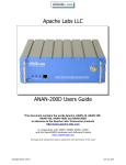
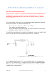
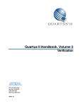
5.2.3 Panadapter
The panadapter uses the data available from the SCU and turns it into a visual representation of the
spectrum instead of audio information. The panadapter display, pictured below, shows the level of
signals present across a specific region of the spectrum just as a spectrum analyzer would. The higher
the white line appears in the display, the stronger the signal is in that part of the band. A scale for the
absolute signal level in dBm (decibels above or below one milliwatt) is provided on the right hand side of
the display. This allows the operator to quickly identify signals of interest where the operator can focus
his efforts.
Each panadapter is derived from the data from a single SCU so it is possible in multiple-SCU radios to
show two different panadapters tuned to the same region of the spectrum, each with data from a
different SCU and ultimately a different antenna. The panadapter shows the most current state of the
spectrum and can be adjusted to show various widths of spectrum. A panadapter can be seen below.
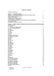
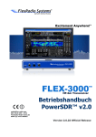
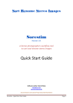
5.2.4 Waterfall
The waterfall uses the same data from the SCU as the panadapter and turns it into a time-based visual
representation of the spectrum. In the waterfall, intensity of signal is represented by a change in color
in a similar way as water density is shown in a weather radar. The vertical position in the waterfall
represents the time that the information on the spectrum was obtained. The waterfall owes its name to
the way that it continually moved downward like a waterfall as time passes. The waterfall can be useful
for understanding how signals are distributed in the spectrum over time, locating where stations have
recently transmitted and even locating “holes” where operation will not interfere with other stations. A
waterfall can be seen below:
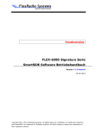
5.2.5 Panafall
The panafall display is simply a panadapter and a waterfall that are joined such that the horizontal
direction has the same frequency location. In this way, the panadapter portion of the display will show
the current state of the spectrum and the waterfall portion will show a historical perspective.
Page 31 of 131
Copyright 2014 FlexRadio Systems. All Rights Reserved.
FLEX-6000 Signature Series - SmartSDR for Windows Software User’s Guide
Page 32 of 131
Copyright 2014 FlexRadio Systems. All Rights Reserved.
FLEX-6000 Signature Series - SmartSDR for Windows Software User’s Guide
6 HOW TO OPERATE A SLICE RECEIVER
6.1
HOW TO CREATE AND DESTROY A SLICE RECEIVER
To add a Slice Receiver click the +RX button
on the left side of the panadapter. This action will
place an additional Slice Receiver resource inside the corresponding panadapter. A Slice Receiver will be
created in the center of the panadapter if none exist. If a Slice Receiver is already present in the
panadapter, the new Slice Receiver will be created with the same basic characteristics (mode, DSP
settings, etc.) as the active or closest Slice Receiver to the center of the panadapter with a mode specific
frequency offset.
When you have utilized all of your available Slice Receiver resources, the Add Slice Receiver button will
turn to a dark shade of grey indicating that the action is no longer available. It will return to an available
state once a Slice Receiver is closed.
If your cursor is already in the position in the display where you would like to create a receiver, you may
right-click the panadapter revealing a pop-up menu which will allow creation of a slice receiver at your
current position.
When a Slice Receiver is within the bounds of a Panadapter, the Close Button
will remove the slice
from the panadapter and will no longer be accessible for receive or transmit audio.
If a slice has moved off screen outside the bounds of a Panadapter, the Slice Receiver display will change
to indicate where the Slice is tuned relative to the Panadapter.
indicator will center the slice in the panadapter. The
enabled on the off screen slice.
Double clicking on the
indicator also will show if the transmitter is
Page 33 of 131
Copyright 2014 FlexRadio Systems. All Rights Reserved.
FLEX-6000 Signature Series - SmartSDR for Windows Software User’s Guide
An Off-Screen slice can be closed by right-clicking on the off-screen indicator and selecting “Close Slice”
or move it on screen by selecting “Move Slice here” as shown below:
If a Slice Receiver moves too far beyond the bounds of the Panadapter, it will be put into a detached
state and will no longer produce audio. Moving the Slice back into the bounds of the Panadapter will
put the Slice Receiver back into a normal state which produces audio.
6.2
HOW TO TUNE A SLICE RECEIVER
Drag Tuning is one of the more common tuning methods. By placing the cursor over the Receive Filter
(lighter blue area of the Slice Receiver) or the carrier (the vertical yellow or red line of the Slice
Receiver), the cursor will change to a small hand icon. Clicking and dragging when the hand icon
appears will change the frequency of the Slice up or down in frequency as the panadapter remains
stationary. This tuning will occur in increments of the currently selected step size. Once the Slice
reaches the edge of the panadapter the Slice will stop and the panadapter will begin to move behind the
slice. This is called Pan Edge Tuning and allows for rapid tuning above or below the panadapters current
frequency range.
Double clicking anywhere in the panadapter grid will initiate a Click Tune. Click tune will move the active
or closest Slice to the frequency where the mouse pointer is located.
Mouse Wheel Tuning occurs when an active slice is selected and the mouse is focused on, and within
the boundaries of, SmartSDR.
FlexControl tuning will tune the active slice regardless of the mouse focus.
The amount of frequency changed by one tuning action on the FlexControl, Mouse scroll wheel or by
dragging is determined by the active slice Tune Step size. Tune Step size is mode group specific and can
be set by the user using the step size adjustment on the Active Slice Widget.
Page 34 of 131
Copyright 2014 FlexRadio Systems. All Rights Reserved.
FLEX-6000 Signature Series - SmartSDR for Windows Software User’s Guide
6.3
MAKING A SLICE RECEIVER ACTIVE
A slice consists of a center Carrier Frequency displayed by a solid yellow
or red
vertical bar. A
yellow bar indicates the slice is “Active,” indicating that this is the slice that you are currently
manipulating. An active slice will have the focus of tuning devices such as the mouse wheel and the
FlexControl. You can toggle the active slice by clicking anywhere on an available slice’s filter display.
When a new Slice Receiver is selected as the Active Slice, the old Active Slice Receiver will become
inactive and its carrier line will change to the red color. There can only be one Active Slice under tuning
device control at a time in SmartSDR.
6.4
HOW TO CHANGE THE DEMODULATION MODE
The Mode Menu button on the Slice Flag displays the mode that is
currently selected. Inside the menu there is a Mode drop down menu
and three quick select modes. To change the quick select modes to a
different mode, use a right click to expose a dropdown menu of
available modes. Beneath the mode select buttons are the mode
specific Filter Presets.
The position of the Receive Filter relative to the Carrier Frequency will correspond to what mode
that you are in. A Receive Filter to the right of the Carrier indicates an Upper Sideband mode. A
Receive Filter to the left indicates a Lower Sideband mode. A Receive Filter that spans both the
left and right of the Carrier will indicate a double sideband mode.
6.5
HOW TO ADJUST THE SPEAKER AND HEADPHONE VOLUME OF A SLICE
RECEIVER
Clicking on the Slice Audio menu button will expose the Slice specific
audio controls. Right clicking on the Slice Audio menu button offers a shortcut for muting audio without
having to enter the menu. The Slice Audio Menu includes a Mute button
and volume slider to
adjust the audio level of the slice. A Left
and Right
balance button and slider to adjust the
balance between left and right channels for headsets or speakers. Automatic Gain Control (AGC)
dropdown menu
allows the user to select Fast, Medium, Slow and Off AGC settings. Finally, the
slider to the right of the AGC dropdown controls AGC Threshold.
Page 35 of 131
Copyright 2014 FlexRadio Systems. All Rights Reserved.
FLEX-6000 Signature Series - SmartSDR for Windows Software User’s Guide
6.6
HOW TO CHANGE THE RX FILTER OF A SLICE RECEIVER
Surrounding the Carrier Frequency bar will be a blue Receive Filter bar
which
represents the filtered receive audio. The portion of spectrum that is highlighted by the Receive Filter
bar will be output as audio.
The Receive Filter width can be adjusted manually by hovering the mouse over the edge of the bar to
get the <-> cursor. Clicking and dragging will expand or reduce the size of the filter.
The Filter Control Widget is used to adjust the high cut and low cut of the Receive Filter. To initiate the
Filter Control Widget, hover your mouse over the Carrier Frequency just above the horizontal axis
Frequency bar. This will cause the Filter Control Widget to appear. Within the control there are three
sections separated by dotted lines.
If you hover your mouse over the left section a left Control arrow will appear. Clicking and dragging left
or right will adjust the low cut of the filter and will display as the left side of the Receive Filter moving
left or right. The measurement at the bottom displays the separation from the carrier frequency.
The center section adjusts both the high cut and low cut of the filter simultaneously. Hovering over the
center section will display a four way arrow. Clicking and dragging up and down from within this section
will decrease/increase the low cut while increasing the high cut of the filter effectively making the
Receive Filter bar wider. Clicking and dragging left and right will move the Receive Filter bar left and
right relative to the Carrier Frequency.
If you hover your mouse over the right section a right Control arrow will appear. Clicking and dragging
left or right will adjust the high cut of the filter and will display as the right side of the Receive Filter
moving left or right. The measurement at the bottom displays the separation from the carrier frequency.
Page 36 of 131
Copyright 2014 FlexRadio Systems. All Rights Reserved.
FLEX-6000 Signature Series - SmartSDR for Windows Software User’s Guide
6.7
RECORDING AND PLAYING A SLICE RECEIVER
Slice receivers may be recorded using the Quick Record/Playback feature of SmartSDR. To the left of
each slice receiver flag are both a record (round) and play button (triangle).
On initial startup, there is no recorded audio in the playback buffer and so the play button will be
disabled (greyed out). To record audio from the slice receiver, press the record button once (circle).
While recording, the record button will animate a repeated pulse.
Recording will continue until the record button is pressed again or until two minutes have passed.
Recording will include any received audio while in receive mode and also any transmit audio when the
radio switches to transmit mode. Once the recording is stopped, the record button will return to a solid
red circle and the play button will be active (Green triangle):
To playback the audio, press the play button (triangle). If the play button is pressed while the radio is in
receive, the playback audio will be routed to the speakers and headphones. If play is pressed while the
radio is in transmit, the audio recording will also play through the transmitter.
To stop playing audio, press the play button a second time or wait for the recorded audio to finish
playing.
To record or play again, press the appropriate button. Only one audio recording per slice receiver is
saved. The audio played during transmit will originate in any playback regardless of whether the slice
receiver the recorded the audio is the slice receiver now transmitting. For example, you may record
audio using slice receiver A and then playback that audio over the air using slice receiver B. To do this,
make slice receiver B the transmitter by selecting it using the red TX selection to the left of the letter B.
Then press PTT on the microphone, footswitch or other PTT source and then press the play button on
slice receiver A.
Page 37 of 131
Copyright 2014 FlexRadio Systems. All Rights Reserved.
FLEX-6000 Signature Series - SmartSDR for Windows Software User’s Guide
7 HOW TO OPERATE THE PANADAPTER/WATERFALL
7.1
HOW TO CREATE/DESTROY A PANADAPTER/WATERFALL
On the lower tool bar of SmartSDR there is a button to create a new Panadapter and Waterfall
.
This control will add another Panadapter to the Main Window. This control will turn to a dark shade of
grey when you have used up the available panadapter resources.
Clicking the Close button
will remove the panadapter and any slices that are displayed in the
panadapter. Once this occurs you will not be able to use the slice resources until they are recreated in a
new panadapter.
7.2
HOW TO CHANGE THE PANADAPTER FREQUENCY (TUNE)
Each panadapter has the ability to perform a pan function to adjust the frequency range that is viewed.
Clicking and dragging within the panadapter grid will reorient the frequencies being viewed on the
panadapter in the direction that your mouse is moving. By moving your mouse to the right you will
display lower frequencies and vice-versa.
The Band menu button
in the Panadapter menu will expose the Band Menu. Selecting a band
from this list will adjust the panadapter display to within the correlating amateur radio band. One band
can be selected at a time and allows for rapid switching between views of the amateur radio bands.
Clicking the Band menu button again will collapse the menu. Clicking on the XVTR button in the lower
right will swap the buttons over to a list of XVTR bands. Click the HF button (same location) to swap
back.
<->
Page 38 of 131
Copyright 2014 FlexRadio Systems. All Rights Reserved.
FLEX-6000 Signature Series - SmartSDR for Windows Software User’s Guide
When switching between bands, if any Slice Receivers were left on the old frequency, these are
removed and one new one will be added. If no Slice Receivers were present, one will not be added at
the new frequency.
7.3
HOW TO ZOOM A PANADAPTER
Each panadapter has a zoom range up to a maximum of 14 MHz for the FLEX-6500 and FLEX-6700 or 7
MHz for the FLEX-6300 down to a minimum of 1.5kHz in bandwidth for the FLEX-6700 and 6kHz in
bandwidth for the FLEX-6500 and FLEX-6300. There are multiple methods for adjusting the zoom of the
panadapter.
The first is by the plus and minus buttons
located in the bottom left corner of the panadapter
and is used for rapid zooming. Zooming out (-) will double the bandwidth presented in the panadapter
while zooming in (+) will cut the bandwidth in half. The frequency at the center of the panadapter will
remain the same after clicking a zoom button.
The second method is a click and drag method using the horizontal axis for more precise zooming. Click
and drag anywhere on the frequency labels located at the bottom of the panadapter to zoom in or out.
The click and drag method will zoom in by dragging to the right and
vice-versa. With this method the frequency at the point where your mouse was located at the click
event will remain stationary in the panadapter.
When zooming out with a FLEX-6000 radio there are certain points where the size of the data used to
create the display on the screen will need to be doubled. As this occurs there will be more noise taken
into account while processing the display which will cause a noticeable increase in the noise floor. The
reverse occurs when zooming in on a panadapter. After zooming out to a certain point, the hardware
will switch to wideband mode. When this occurs, any panadapters that are affected by this change will
display
in the top right corner to indicate that it is in wideband mode. When in Wideband the
radio will open up the Bandpass Filters as wide as they can go for any panadapters or slice receivers that
are using that Antenna. Note that the FLEX-6300 is always in WIDE mode and will not show this
indicator.
Just to the left of the WIDE indicator is a spot for indicating whether the preamplifier is active and at
what level. This indicator will normally be hidden. See section 24.1 for a complete description of
preamplifier control.
One more step to the left is a spot for indicating whether the Panadapter is on a Transverter (XVTR)
band. This indicator will normally be hidden. See section 22 for a complete description of how to setup
for XVTR operation.
Page 39 of 131
Copyright 2014 FlexRadio Systems. All Rights Reserved.
FLEX-6000 Signature Series - SmartSDR for Windows Software User’s Guide
7.4
HOW TO CHANGE THE SIGNAL MAGNITUDE SCALE OF A PANADAPTER
Each panadapter will allow you to adjust the maximum and minimum amplitude displayed. Clicking the
up or down arrows
displayed in the top right corner of the panadapter will increase or decrease
respectively the maximum amplitude displayed in 10 dB increments. You may also adjust the minimum
amplitude by clicking and dragging the vertical axis. This will effectively adjust where the noise floor is
positioned within the panadapter.
7.5
ADJUSTING THE PANADAPTER AND WATERFALL CONTROLS
Display menu button
on the Panadapter menu will expose display controls. A horizontal line
separates panadapter controls (top) from waterfall controls (bottom).
The FPS slider controls the Frames Per Second that the Frequency Line is drawn at. Lowering the FPS
control has several effects:
It lowers the rate at which both the panadapter and the waterfall are updated
It lowers the network bandwidth of data sent from the radio to the client (important in
situations where you may have limited bandwidth)
As the rate of update is lowered, the extra data not displayed is averaged and so the variance of
the data is lowered, making both the panadapter and the waterfall smoother
If you prefer a faster updating display, but a more averaged or smoother one, adjust the FPS setting for
the update speed you prefer and then raise the AVG (averaging) control. The AVG control increases the
number of frames that are averaged, lowering the variance and smoothing the display.
Page 40 of 131
Copyright 2014 FlexRadio Systems. All Rights Reserved.
FLEX-6000 Signature Series - SmartSDR for Windows Software User’s Guide
The final panadapter control, Weighted Average, emphasizes signals that are increasing in amplitude
over ones that are declining. This has a tendency to continue to show locations where signals have been
and show a more precise view of their full amplitude when they first appear.
Below the line at the center of the control are the Waterfall controls.
The Gain, Black and Auto controls work together to adjust how different signal levels are displayed in
the waterfall. The Black control sets the level below which all pixels will render as black. In other words,
it sets the level at which signals are no longer of interest. The Auto control will automatically set the
black level to just below the noise as band conditions, preamplifier changes or antenna changes alter
the noise floor. To enable auto-black, click the Auto button so that it is blue.
The Gain control adjusts how rapidly the waterfall will advance through the color spectrum for minimal
changes in signal level. Adjusting gain low gives the waterfall a broader dynamic range, but lessens its
ability to show small variations signals. Raising the gain lowers the dynamic range, but provides more
detail in the variances in smaller signals’ magnitudes.
The rate control adjusts how fast the waterfall will advance on the screen. At the lowest setting, many
minutes of data can be persisted on the display. On its highest setting, the waterfall displays a rapidly
changing spectrum in the most detail.
Page 41 of 131
Copyright 2014 FlexRadio Systems. All Rights Reserved.
FLEX-6000 Signature Series - SmartSDR for Windows Software User’s Guide
In most cases Auto Black properly adjusts the background color or black level for the display’s zoom
factor and the relative noise floor of the band you are viewing. You can however manually adjust the
Waterfall display’s setting to allow for the display of weak signals at or near the noise floor. If the black
level is set too low, many of the "in the noise" FFT bins will always be zero, regardless of the display gain
setting. To achieve and ideal setting for adjusting the waterfall black level, do the following:
Turn the display gain level to maximum
Adjust the waterfall black level to a point where the waterfall is primarily white, but there
are approximately 2-5% black areas displayed.
Turn the display gain down until the background is deep blue.
This ensures that small signals in the noise will be seen.
7.6
HOW TO CHANGE THE SIZE AND POSITION OF MULTIPLE PANADAPTERS
Clicking the Maximize button
will prioritize the arrangement of the panadapter at the top of the
display. Once a panadapter is maximized a grey horizontal separator will appear between the maximized
panadapter and any other panadapters that are open at the time. Clicking and dragging this horizontal
separator will increase or decrease the available size for the maximized panadapter. The non-maximized
panadapters will adjust to fill the remaining available space. To return to the standard view click the
next to the close button. You can have up to three maximized panadapters at a time.
When multiple panadapters are open, clicking on the main bar and dragging its position will rearrange
the panadapter windows.
Page 42 of 131
Copyright 2014 FlexRadio Systems. All Rights Reserved.
FLEX-6000 Signature Series - SmartSDR for Windows Software User’s Guide
When multiple panadapters are open, clicking on the main bar and dragging its position will rearrange
the panadapter windows.
Page 43 of 131
Copyright 2014 FlexRadio Systems. All Rights Reserved.
FLEX-6000 Signature Series - SmartSDR for Windows Software User’s Guide
8 TRACKING NOTCH FILTERS
8.1
TRACKING NOTCH FILTER (TNF) THEORY
With notch filters found on most receivers, the notch is removing an audio frequency after the AGC.
When you hear a carrier in the middle of a sideband transmission, you can enable the notch and adjust
it to remove the objectionable carrier. This issue with this type of notch is apparent when the dial
frequency is changed. Since the notch is on an audio frequency offset, as the dial frequency is changed
the audio frequency of the undesirable frequency is changed and it falls out of the notch, requiring a
readjustment of the notch.
With the Tracking Notch Filter™ (TNF), once the frequency has been notched the filter remembers the
RF frequency of the objectionable signal. When the dial frequency is changed, the filter is automatically
adjusted to maintain the notch on the objectionable frequency. With SmartSDR, you can have a large
number of Tracking Notch Filters to notch out local problem carriers or birdies across all bands covered
by SmartSDR. The TNFs may be temporary, for only the current session, or they may be remembered
permanently.
8.2
CREATING AND ADJUSTING A TRACKING NOTCH FILTER (TNF)
To create a TNF, click the
button on the left side of the panadapter. This will create a TNF in
the center of the panadapter. You can also right click in the panadapter or waterfall on the frequency
where you would like the TNF created and select “Create TNF.”
The Tracking Notch Filter will be created on the frequency where the right-click occurred. A TNF will be
shown by a greenish vertical line with diagonal stripes.
Page 44 of 131
Copyright 2014 FlexRadio Systems. All Rights Reserved.
FLEX-6000 Signature Series - SmartSDR for Windows Software User’s Guide
Once the TNF is created, the TNF may be remembered, deleted or additional notch depth may be added
by right-clicking on the TNF again:
To see details on the current TNF or change its frequency or width, hover your cursor over the TNF. The
cursor will change to a 4-way directional cursor and details about the TNF will appear in a callout:
To increase the width of the TNF, left-click and then move the cursor up-and-down. To adjust the
frequency of the TNF, slice side-to-side.
Page 45 of 131
Copyright 2014 FlexRadio Systems. All Rights Reserved.
FLEX-6000 Signature Series - SmartSDR for Windows Software User’s Guide
8.3
TURNING ON OR OFF ALL TRACKING NOTCH FILTERS (TNF)
To disable all TNFs at the same time, click on the TNF icon in the bar at the bottom on SmartSDR:
When all TNFs are disabled, the TNF icon will “gray out” as shown below. To re-enable all TNFs, just click
on the button again.
Page 46 of 131
Copyright 2014 FlexRadio Systems. All Rights Reserved.
FLEX-6000 Signature Series - SmartSDR for Windows Software User’s Guide
9 HOW TO REPROGRAM A FLEXCONTROL
From the “Settings” dropdown menu at the top of SmartSDR, select the “FlexControl” option.
This will bring up the simple mode FlexControl panel.
The panel resembles the physical appearance of the actual FlexControl to make the programming
experience more intuitive. Each of the buttons have a corresponding drop down menu that allows the
user to modify its function.
Page 47 of 131
Copyright 2014 FlexRadio Systems. All Rights Reserved.
FLEX-6000 Signature Series - SmartSDR for Windows Software User’s Guide
The different options include:
Tune Slice – When enabled the knob will tune the active slice
RIT (Receive Incremental Tuning) – When enabled the knob will tune the RIT of the
active slice. Double clicking the button will zero the RIT setting.
XIT (Transmit Incremental Tuning) – When enabled the knob will tune the XIT of the
active slice. Double clicking the button will zero the XIT setting.
Slice AF – When enabled the knob will adjust the volume of the active slice
Master AF – When enabled the knob will adjust the master volume control
AGCT (Automatic Gain Control Threshold) – When enabled the knob will adjust the
AGCT of the active slice.
CWX Macros – When selected, pressing the button will send the selected CWX Macro
None
Page 48 of 131
Copyright 2014 FlexRadio Systems. All Rights Reserved.
FLEX-6000 Signature Series - SmartSDR for Windows Software User’s Guide
10 HOW TO IMPORT AND EXPORT RADIO SETTINGS
From the “Profiles” dropdown menu select “Import/Export Profiles”
This will bring up the Import/Export window:
Select the corresponding tab for import or export controls. The “Browse” button on the Import tab will
bring up a Windows Explorer window that can be directed to the file being imported. The user can check
the items that they wish to import/export by clicking on one of the circles
next to the setting. When
selected a checkbox will display inside the circle . Checking/unchecking the circle next to select all will
select/deselect all the subsequent options. Click “Import” or “Export” to complete the process. Clicking
“Export” will prompt the user to save the file to a specified location. NOTE: Exports will only contain
profiles that the user set and will not include the default profiles built into SmartSDR.
Page 49 of 131
Copyright 2014 FlexRadio Systems. All Rights Reserved.
FLEX-6000 Signature Series - SmartSDR for Windows Software User’s Guide
11 HOW TO SAVE AND CHANGE PROFILES
Profiles allow the user to name and save the entire state of the radio and recall it later. Profiles can
even be exported and restored on another FLEX-6000 Series radio. This facilitates convenient backup
and also helps IT managers at DXpeditions or contest super-stations test configurations and then install
them or restore them at a site. Individual operators can also save their favorite settings and then after
others have operated, restore the state of the radio to where it was. [Note: Graphical User Interface
layout settings are not stored in v1.3 but may be included in a future version.]
There are two types of profiles: GLOBAL and TRANSMIT profiles. Global profiles store the state of the
radio including the panadapters and slices that are open, the current modes and all of the settings for
noise blanker, AGC, filters, etc. There are also transmit profiles that can be used to store a profile for a
specific microphone or operating style.
Profiles are far superior to traditional "band stacking" in that you can save as many different
configurations as desired and give them a meaningful name for recall. The user can leave the Profile
Manager open to the side of the SmartSDR window and instantly switch configurations by double
clicking the desired profile.
11.1 SAVING AND DELETING PROFILES
From the “Profiles” dropdown select the option “Save Global Profile” or “Save Transmit Profile”
This will bring up the Profile Manager Window
Page 50 of 131
Copyright 2014 FlexRadio Systems. All Rights Reserved.
FLEX-6000 Signature Series - SmartSDR for Windows Software User’s Guide
There are two tabs at the top of the window and the tab that is selected will correspond to which menu
option the user selected. Type the desired profile name into the text box at the top that says “New
Profile Name” and click save or hit the Enter key on the keyboard to save a new profile. Saving a Global
profile will save all of the current settings for the radio. Saving a Transmit profile will save only the
settings related to transmit.
To delete the profile, select the profile name and click the delete button.
Page 51 of 131
Copyright 2014 FlexRadio Systems. All Rights Reserved.
FLEX-6000 Signature Series - SmartSDR for Windows Software User’s Guide
11.2 LOADING PROFILES
To load a profile from the Profile Manager Window, select the desired profile and click load or just
double click on the profile name.
After a profile is saved a quick selection option becomes available on the Profiles drop down menu to
rapidly change between saved profiles.
Global profiles can quickly be changed from the “Profiles” dropdown menu. The saved profiles will show
up under the “Profile Manager” selection.
Different Transmit profiles can quickly be selected from the dropdown menu on Transmit Panel above
the “Tune” and “MOX” button.
Page 52 of 131
Copyright 2014 FlexRadio Systems. All Rights Reserved.
FLEX-6000 Signature Series - SmartSDR for Windows Software User’s Guide
12 HOW TO OPEN AND CLOSE THE TRANSMIT CONTROL PANEL
To display the Transmit Control Panel click on the Transmit Control Panel icon, shown below, in the
lower left hand corner of the SmartSDR application window. Clicking the icon again will remove the
Transmit Control Panel
Page 53 of 131
Copyright 2014 FlexRadio Systems. All Rights Reserved.
FLEX-6000 Signature Series - SmartSDR for Windows Software User’s Guide
13 HOW TO DETERMINE THE IP ADDRESS OF THE RADIO AND THE
SOFTWARE VERSION NUMBERS
Bring up the Radio Setup Panel by clicking the “Settings” dropdown menu at the top left of SmartSDR.
Then select “Radio Setup”.
Located in the “Radio” tab is basic information about the selected radio. Radio Hardware version refers
to the software and firmware that is loaded into the radio itself.
Located in the “Startup” tab is information about the client. Client Software refers to the software that
runs on your computer to operate the radio.
Page 54 of 131
Copyright 2014 FlexRadio Systems. All Rights Reserved.
FLEX-6000 Signature Series - SmartSDR for Windows Software User’s Guide
14 HOW TO GET TECHNICAL SUPPORT AND ASSISTANCE
You can get technical support by opening a HelpDesk support ticket (helpdesk.flexradio.com) or by
calling at 512-535-4713 x2.
Another great resource is our online community (community.flexradio.com) where FlexRadio Staff and
other FlexRadio Operators post Ideas, Questions, Praises, Problems and solutions. The community has
powerful search capabilities that allow you to easily locate solutions to questions that others have
previously asked.
15 HOW TO UPDATE THE SOFTWARE
In the event where the current Radio Hardware version is not compatible with the current Client
Software version, an update will be required. You will notice that there is a yellow indicator
followed by the text “Update” in the list box where your radio is listed. You will also notice text requiring
you to update your radio before you can proceed. In order to resolve the discrepancy, click
. As long as your radio is advancing to a more recent revision it will begin the update
process. If the Client Software requires an older Radio Hardware version, a pop up window will be
shown to ensure that this is being done intentionally.
Clicking the Downgrade button will remove the current version of software and load a previous older
version to be compatible with the client software you are currently running. Click
to
proceed. Click
to maintain the existing version of Radio Hardware. (Note: If you were not
intending to downgrade the radio, check to make sure that you are running the correct version of
SmartSDR.)
Once the process has started you will see a progress bar showing the approximate completion status.
Upon completion of the update you will see
appear next to the radio in the list box.
Page 55 of 131
Copyright 2014 FlexRadio Systems. All Rights Reserved.
FLEX-6000 Signature Series - SmartSDR for Windows Software User’s Guide
16 HOW TO OPERATE CW
To use SmartSDR in CW mode, select CW in the slice control panel. This will automatically bring up the
CW specific controls in the transmit panel, and show the narrower CW receive filter presets.
The CW display is slightly different from the SSB display. In CW mode, the slice carrier indicator line is in
the center of the receiver passband. This coincides with the CW carrier frequency, and takes into
account the CW pitch offset. It shows exactly the location of your transmitted carrier.
16.1 HOW TO OPERATE CW IN SPLIT MODE
Many DXpeditions prefer to operate split mode, where they transmit on a frequency, but listen up or
down a few kilohertz. In order to do this in SmartSDR, you must add a second slice receiver to the
panadapter to use as your secondary frequency. To add a slice, click the
side of the screen. Your panadapter display should look like this:
Page 56 of 131
Copyright 2014 FlexRadio Systems. All Rights Reserved.
button on the left
FLEX-6000 Signature Series - SmartSDR for Windows Software User’s Guide
Slice receiver A should be tuned to the DX station’s transmitting frequency. Slice receiver B should be
selected as the active slice so you can tune your transmit frequency to where the DX station is listening.
Select TX enable on slice B so your transmitter will follow.
If you prefer, you can use the slice audio controls to pan the slice audio so one receiver is in your left ear
and the other is in your right ear.
16.2 CW TRANSMITTING
In order to transmit CW, you will need either a straight key, or an iambic paddle if you want to use the
built-in keyer. Refer to the FLEX-6000 Hardware Reference Manual for wiring instructions.
Page 57 of 131
Copyright 2014 FlexRadio Systems. All Rights Reserved.
FLEX-6000 Signature Series - SmartSDR for Windows Software User’s Guide
If you want to use a straight key, uncheck the IAMBIC control in the CW transmit panel. The BREAKIN
control allows automatic PTT when the key is pressed. The Delay slider sets the PTT hold time for breakin in milliseconds. It can be set anywhere from zero (full QSK), to 2000 milliseconds (2-seconds).
16.3 USING THE BUILT-IN KEYER
The radio has a built-in iambic keyer that can be used either as iambic “A” or iambic “B”. These settings
are on the CW tab of the Radio Setup panel. It is also possible to swap the dot and dash paddles in
software.
The keyer speed can be set anywhere between 5 and 100 WPM using the Speed control in the CW
transmit panel. The IAMBIC selector must be enabled to use the built-in keyer. The Sidetone control
will increase or decrease the sidetone volume in the speakers and headphones.
Page 58 of 131
Copyright 2014 FlexRadio Systems. All Rights Reserved.
FLEX-6000 Signature Series - SmartSDR for Windows Software User’s Guide
16.4 HOW TO OPERATE QRQ (HIGH SPEED) CW WITH QSK
The FLEX-6000 is capable of full QSK operation. In order to use QSK, the delay control must be set to
zero. This will allow the transmit/receive switching to occur immediately upon release of the key. The
FLEX-6000 uses very fast reed relays in the CW T/R switching, but at extremely high CW speeds, above
60 WPM, you will get better inter-element receiving results using one antenna for transmit and a
different antenna for receive. Refer to the antenna selection instructions for information on how to
configure separate transmit and receive antennas. (QRQ is only available on FLEX-6700)
16.5 HOW TO CONNECT AN EXTERNAL KEYER USING THE FSK/KEY INPUT ON
THE REAR PANEL ACCESSORY CONNECTOR
In CW mode, the FSK/Key (Pin 4) input on the rear panel accessory connector can be used as a straight
key input. This is useful if you wish to attach an external keyer, such as a K1EL WinKeyer, microHAM
microKEYER, or other contest-oriented interface. This input is always active, and is not affected by the
FLEX-6000 internal keyer settings. It’s therefore possible to use both the external keyer, and the
internal keyer at the same time.
Page 59 of 131
Copyright 2014 FlexRadio Systems. All Rights Reserved.
FLEX-6000 Signature Series - SmartSDR for Windows Software User’s Guide
17 HOW TO OPERATE SINGLE SIDEBAND (SSB)
To use SmartSDR in SSB mode, select either USB or LSB in the slice mode select control panel. This will
automatically bring up the SSB specific controls in the transmit panel, and show the wider receive filter
presets. The image above shows the slice receiver in USB mode. USB and LSB are automatically
selected for the normal mode of operation for each band when the band selection panel is used.
To select the opposite SSB mode, click on the mode indicator as shown above. In this example, LSB can
then be selected from the drop down menu to the left of the USB indicator.
In SSB modes, the slice carrier indicator line will be located to the left of the receiver passband for USB
and to the right for LSB. It shows exactly the location of your transmitted SSB suppressed carrier
frequency. If the slice is the active slice, the carrier indicator line will be displayed in yellow and with a
triangular arrow at the top. All other slices are displayed with no arrow and have red carrier indicators.
17.1 HOW TO SELECT THE SSB FILTER BANDWIDTH
Standard SSB filter bandwidths from 1.6K to 4.0K can be selected from the drop down panel under the
mode selection button as shown below. Custom bandwidths can be adjusted either by clicking and
Page 60 of 131
Copyright 2014 FlexRadio Systems. All Rights Reserved.
FLEX-6000 Signature Series - SmartSDR for Windows Software User’s Guide
dragging the side of the filter display on the panadapter or by using the filter widget control enabled by
hovering the mouse at the bottom of the carrier indicator.
17.2 OPERATING THE SPEECH PROCESSOR
The speech processor, shown below in the red square, may be on or off and has three different settings
if turned on. In the NOR or normal setting, the processor provides minimal additional gain and simply
prevents audio peaks from clipping or producing excess power (than what has been set). In the DX
setting, more gain is provided to the audio to increase the overall sideband envelope which results in a
stronger signal that may be more readily heard at a distance. The DX+ setting adds even more gain
increasing your talk power or “punch” without incurring audio distortion. DX+ is most effective if you
increase the low cut TX filter to between 200-400 Hz in order to concentrate your talk power in the
audio frequency range that has the greatest intelligibility.
The recommended setting is to leave the speech processor enabled and in the NORmal position.
17.3 HOW TO OPERATE SSB IN SPLIT MODE
Many DXpeditions prefer to operate split mode, where they transmit on a frequency, but listen up or
down a few kilohertz. In order to do this in SmartSDR, you must add a second slice receiver to the
panadapter to use as your secondary frequency. To add a slice, click the
side of the screen. Your panadapter display should look like this:
Page 61 of 131
Copyright 2014 FlexRadio Systems. All Rights Reserved.
button on the left
FLEX-6000 Signature Series - SmartSDR for Windows Software User’s Guide
Slice receiver A should be tuned to the DX station’s transmitting frequency. Slice receiver B should be
selected as the active slice so you can tune your transmit frequency to where the DX station is listening.
Click on TX on slice B so your transmitter will follow the active slice.
If you prefer, you can use the slice audio controls to pan the slice audio so one receiver is in your left ear
and the other is in your right ear.
17.4 HOW TO CONFIGURE YOUR AUDIO CONTROLS FOR VOICE MODES
Connect a suitable microphone to the 8-pin front panel connector or to the balanced microphone input
following the instructions provided in the FLEX-6000 Hardware Reference Manual. In the transmitter
control panel, select “MIC” for the front panel microphone or “BAL” for the rear panel balanced
microphone input.
Page 62 of 131
Copyright 2014 FlexRadio Systems. All Rights Reserved.
FLEX-6000 Signature Series - SmartSDR for Windows Software User’s Guide
Transmitter Low Cut and High Cut bandwidth can be set on the Transmit Control panel. The bandwidth
is adjustable up to 10 KHz in 1 Hz increments.
There are two indicator components of the microphone or input Level meter to show the actual audio
input level. The left most component is a solid bar indicating the average input level and the smaller
box like component farther to the right of the average input level bar is the peak level indicator. The
Level meter indicator bars also utilize three colors to visually indicate the input level range. Signals up to
-10 dB are shown in green. Signals levels between from -10 and 0 dB are shown in yellow. Any signal
level that is greater than 0 dB is shown in red.
When setting up your microphone audio for optimal modulation, adjust the input gain so that the peak
level indicator is peaking just BELOW the 0 dB on voice peaks. It is very important that your peak level
indicator never exceed 0 dB and turn red at any time. A red peak level indicator indicates over-driven or
“clipped” input audio levels resulting in audio distortion. The input ALC is active, but excessive input
signal levels will result in input signals that can exceed 0 dB. If you see the peak level indicator turn red
at any time, turn down your audio input gain until you no longer see the peak level indicator turn read.
Page 63 of 131
Copyright 2014 FlexRadio Systems. All Rights Reserved.
FLEX-6000 Signature Series - SmartSDR for Windows Software User’s Guide
The Transmit Equalizer control panel is illustrated above with the TX and ON buttons highlighted. With
these buttons selected, the graphic EQ can be optimized for different microphones and operating styles
such as DX, contesting and ESSB. The sliders provide a +/- 10 dB adjustment range over eight octaves.
The settings shown above provide very good audio quality for many dynamic microphones.
17.5 MONITOR MODE OPERATION
The MON button allows monitoring of the processed audio prior to the final brick wall filtering and ALC
limiter. This gives a real time indication of compression and equalization settings on the transmitted
audio. Monitor mode is enabled by engaging the MON button so that the monitor level may be
controlled by the adjacent slider.
17.6 RECOMMENDED AUDIO ADJUSTMENT STEPS FOR VOICE MODES:
1. Select the desired microphone input from the drop down menu.
2. Select the desired transmit filter width on the Setup/Voice panel.
3. Turn the compressor off by pressing the PROC button so that it is not highlighted.
4. Adjust the TX Equalizer to compensate for the microphone and operating conditions. The
default setting is optimized for most microphones. The TX EQ is located after the
compressor/expander so it should typically be adjusted prior to engaging the
compressor. Minor adjustments can be done after engaging the compressor/expander but care
is needed to avoid excessive peaks.
Page 64 of 131
Copyright 2014 FlexRadio Systems. All Rights Reserved.
FLEX-6000 Signature Series - SmartSDR for Windows Software User’s Guide
5. Speak into the microphone at the loudest voice level you would normally use.
6. Adjust the microphone gain control so that the peak indicator hovers near 0 VU on the Level
meter. Some low output dynamic studio microphones may require the +20 dB gain selection
located on the Setup/Voice panel.
7. Turn on the TX compressor/expander with the COMP button. The compression slider controls
the Compression Threshold. At the minimum setting, the threshold is 0 dB while at max the
threshold is approximately -33 dB. The compression ratio is fixed at 5:1 while the downward
expander set for a threshold of -45dB with a ratio of 4:1.
8. Adjust the compression level control to the right of the COMP button to achieve the desired
compression for the desired style of operation (e.g. DX/Contesting, ESSB, etc.). Note that the
peak level indicated on the meter should not change significantly but the average should
increase in proportion to the compression level. A normal compression level will be about -10
dB.
9. Adjust the transmit equalizer to optimize the audio for the desired operating style and
microphone response.
10. If VOX operation is desired, enable the VOX button and adjust VOX gain/delay for proper
operation.
17.7 HOW TO OPERATE VOX
Press the
button to enable voice operated transmit operation and adjust the VOX gain slider to
adjust the VOX sensitivity. Sensitivity should be adjusted to the minimum that allows reliable keying by
the voice without keying from other room noises. VOX delay sets the hang time before the transmitter
unkeys after you stop speaking. Delay should be set to be comfortable for the style of operation
desired.
Page 65 of 131
Copyright 2014 FlexRadio Systems. All Rights Reserved.
FLEX-6000 Signature Series - SmartSDR for Windows Software User’s Guide
18 HOW TO OPERATE AM AND SAM
To operate AM or Synchronous AM (SAM) mode, select AM or SAM on the mode drop down menu. The
receive AM bandwidth is selected on the drop down along with the mode selection. The carrier
frequency indicator is shown at the center of the filter passband. Note that the filter bandwidth may be
adjusted on either side by dragging the side of the filter with the mouse. This allows asymmetrical filter
settings to get rid of heterodyne carriers or other interference on one side of the desired signal.
The AM Carrier control allows the carrier level to be set while maintaining a constant overall PEP output
of the transmitter. With the AM Carrier control at full scale, standard 25% carrier operation is provided.
When both the RF Power and AM Carrier controls are set to maximum, the carrier level will be
approximately 25W and PEP output will be 100W. Reducing the RF Power control will reduce the carrier
level and PEP in proportion. By reducing the AM Carrier level, the percentage of carrier relative to total
PEP can be reduced to increase talk power in the AM sidebands. This is called Reduced Carrier AM.
Page 66 of 131
Copyright 2014 FlexRadio Systems. All Rights Reserved.
FLEX-6000 Signature Series - SmartSDR for Windows Software User’s Guide
19 HOW TO OPERATE DIVERSITY RECEPTION (FLEX-6700 ONLY)
Diversity Reception is a powerful method for improving the reliability of a message signal by
using two or more communication channels with different characteristics. Diversity is very
useful for aid reception in weak and fading (QSB) signal conditions. With optimally configured
antennas, weak signal QSB copy can be improved up to 75%.
Two common diversity methods are space and polarization. Both of these methods use separate
antennas to receive different versions of the same signal. The FLEX-6700 incorporates two fully
independent Spectral Capture Units (SCUs) that allow two separate antennas to be
simultaneously digitized. The analog to digital converters (ADCs) on the respective SCUs are
driven from a single clock source to provide stable synchronous reception. Since the FLEX-6500
and FLEX-6300 use a single SCU, they are not capable of diversity reception.
For best results antennas should be de-correlated in some way so that fading on one antenna is
likely to be seen as increased signal strength on the other antenna. De-correlation can be
accomplished by using different types of antennas (dipole and vertical), using the same type
antenna at wide spacing (e.g. multiple wavelengths), or using the same antenna with different
polarizations (horizontal and vertical or right and left). The more de-correlated the antennas the
better but even small amounts can be beneficial. One interesting example of the application of
circular polarization diversity on HF is discussed in the December 2010 QST article, “Gimme
and X, Gimme an O, What’s that Spell? – Radio.”
The diversity implementation provided in SmartSDR v1.3 is intended for use only with
headphones. Two Slice Receivers attached to separate antennas are automatically routed to the
left and right ears so that the brain can provide discrimination between the signals. The reason
speakers are not used is that they allow the signals to combine in the space between the speakers
to cause undesirable peaks and nulls in the sound. For example, Slice A could be set to RXA
and Slice B to RXB.
As seen in the screen shot below, a weak SSB signal has been tuned on Slice A attached to
ANT1. The DIV button has been selected on the slice DSP drop down to enable Diversity and
pop up the slaved diversity Slice B on ANT2 locked to the same frequency as Slice A. Note that
RXA, RXB, and XVTR ports are also available for receiver inputs. SmartSDR automatically sets
the slice audio faders to place the two antennas the left and right ears respectively. Your brain
does the rest. Remember that the sound will be very different from normal reception since you
are literally listening in stereo to the same signal on two different antennas.
Page 67 of 131
Copyright 2014 FlexRadio Systems. All Rights Reserved.
FLEX-6000 Signature Series - SmartSDR for Windows Software User’s Guide
SmartSDR automatically sets the slice audio faders to place the two antennas in the left and right
ears respectively. The sound will be very different from normal reception since the user is
listening in stereo to the same signal on two different antennas.
20 HOW TO OPERATE THE ATU
Press the
button to initiate tuning on the Automatic Tuning Unit. The ATU will set the power
output to approximately 2W on 6m and 10W on all other bands. The ATU will tune until it achieves a
successful impedance match as shown by the
indicator. The
button will remain lit to
show that the ATU is engaged. If the ATU cannot achieve a successful match, the red
light and the tuner will revert to bypass mode.
indicator will
In the event that the measured antenna SWR is lower than the ATU than the final tuning outcome, the
ATU will switch into bypass mode indicated by the highlighted
will light.
button and the
Page 68 of 131
Copyright 2014 FlexRadio Systems. All Rights Reserved.
indicator
FLEX-6000 Signature Series - SmartSDR for Windows Software User’s Guide
21 HOW TO CONFIGURE ANTENNAS
21.1 GETTING STARTED
When SmartSDR starts for the first time, it loads a single panadapter and slice receiver with
Antenna 1 (ANT1) selected by default. Transceive operation is then functional on ANT1 with no
further setup or adjustment required.
21.2 SELECTING THE RECEIVE ANTENNA FOR A PANADAPTER WITHOUT
SLICE RECEIVERS
The display above shows a single panadapter without any Slice Receivers activated. The
panadapter receive antenna is selected on the ANT pop out menu on the left side of each
panadapter. LoopA or LoopB (Not available on FLEX-6300) may be selected along with the RF
Gain for the associated panadapter.
21.3 USING THE PANADAPTER ANT POP OUT MENU
The pop out menus provide receive antenna selection and RF Gain control for the FLEX-6700
(left), FLEX-6500 (center) and FLEX-6300 (right). Changing the configuration on this menu affects
the receiving setup for all slices located on its panadapter. Changing the receiving antenna on any
slice within the panadapter changes the configuration for its panadapter and all slices located
within.
Page 69 of 131
Copyright 2014 FlexRadio Systems. All Rights Reserved.
FLEX-6000 Signature Series - SmartSDR for Windows Software User’s Guide
The slice receiver flags allow drop down selection and annunciation of the receive antenna
selected for its panadapter and all respective slices located therein. The left flag shown above
shows the options allowed on a FLEX-6700, the center flag shows those available on the FLEX6500 and the right flag shows the FLEX-6300. The RX B input selection is only available on the
FLEX-6700 since it contains two independent SCUs.
Loop selection is provided only from the panadapter ANT menu but is indicated under the receive
antenna selector on each slice within the respective panadapter. The LoopA annunciator can be
seen under ANT1 in the Slice A flag shown above. This means that the RX A loop is active and
connected to ANT1.
21.4 SELECTING THE TRANSMIT ANTENNA FOR A SLICE RECEIVER
The transmit antenna for each slice is selected from the red drop down menu shown on Slice A
above. The transmit antenna selector offers the same ANT1, ANT2, and XVTR options on both the
FLEX-6500 and FLEX-6700 models. Each slice may have its own designated transmit antenna that
is activated by the large red TX button to the left of its slice letter (e.g. Slice A in above).
21.5 ANTENNA OPTIONS FOR PIN DIODE QSK OPERATION
Page 70 of 131
Copyright 2014 FlexRadio Systems. All Rights Reserved.
FLEX-6000 Signature Series - SmartSDR for Windows Software User’s Guide
Full QSK operation with reception between individual elements is supported on a single
transceive antenna at speeds up to 30 WPM. QRQ QSK is supported at 100+ WPM when a
separate receive antenna is used on RX A, RX B or XVTR. The QSK annunciator located to the left
of the TX selector button on each flag indicates that QSK is operational in the selected mode. QSK
is not supported with a separate receive antenna set to either ANT1 or ANT2.
21.6 USING A COMMON RECEIVE ANTENNA WITH SEPARATE TRANSMIT
ANTENNAS
The display above illustrates two panadapters on a single receive antenna (ANT1) but having
separate transmit antennas on ANT1 and ANT2 respectively. Slice A and B both have ANT1
selected. Slice A has ANT1 selected as the TX antenna and Slice B has ANT2 selected as the TX
antenna. Clicking on the TX indicator for the slice changes the TX indicator to red and activates
the respective slice as the transmitter with its TX antenna.
Page 71 of 131
Copyright 2014 FlexRadio Systems. All Rights Reserved.
FLEX-6000 Signature Series - SmartSDR for Windows Software User’s Guide
21.7 USING TWO TRANSCEIVE ANTENNAS ON THE FLEX-6700
In the display above, the Slice A is set to receive and transmit on ANT1. Slice B is set to receive
and transmit on ANT2. The Slice B is selected as the active transmit frequency of 7.033 MHz on
ANT2 as indicated by the red TX button. To move the transmit frequency to 14.225 MHz on ANT1,
simply click the TX button on Slice A.
21.8 USING A DEDICATED RECEIVE ANTENNA
The above display shows Slice A having a dedicated receive antenna on RX A with the transmit
antenna ANT1. The FLEX-6700/6700R models have the option of two separate receive antennas
on RX A and RX B respectively. The FLEX-6500 has only the RX A option. The FLEX-6300, FLEX6500 and FLEX-6700 all have the option of receiving from the XVTR port. The XVTR port is not
recommended as a receive antenna port if an external preamp is used on its antenna.
Transmission on the XVTR port could put up to +10 dBm of reverse power into the connected
preamp.
Page 72 of 131
Copyright 2014 FlexRadio Systems. All Rights Reserved.
FLEX-6000 Signature Series - SmartSDR for Windows Software User’s Guide
21.9 RECEIVE ONLY ANTENNA OPERATION
The display above is configured on a FLEX-6700 so that Slice A receive antenna is set to RX A and
Slice B to RX B. ANT1 is selected as the transmit antenna for Slice A and ANT2 for Slice B. This
configuration allows separate receive antennas on the two independent SCUs. This configuration
is not available on the single SCU FLEX-6500 or FLEX-6300. In the above illustration, Slice A is
selected as the transmit frequency. To change the transmitter to Slice B, simply click its TX
button.
21.10 ANTENNA SELECTION FOR TRANSVERTER OPERATION
The left slice flag above shows XVTR selected for both receive and transmit antennas. This
provides common transverter port transceive operation. The slice flag on the right illustrates the
setup where RX A is set as the receive antenna and XVTR as the transmit antenna. This mode
supports split transmit/receive transverter operation.
Page 73 of 131
Copyright 2014 FlexRadio Systems. All Rights Reserved.
FLEX-6000 Signature Series - SmartSDR for Windows Software User’s Guide
21.11 ANTENNA CONFIGURATION BASIC TERMS AND RULES
For more advanced antenna configurations it is helpful to define terms used to describe the FLEX6000 Signature Series architecture and the rules associated with its configuration.
1. A Spectral Capture Unit (SCU) is a direct sampling, wideband digitizer that captures the entire RF
spectrum within its input filter limits.
2. The FLEX-6700/6700R models contain two fully equivalent but independent SCUs. The FLEX6500 and FLEX-6300 contain a single SCU.
3. The FLEX-6700/6700R models can simultaneously digitize two antennas, one for each SCU, while
the FLEX-6500 and FLEX-6300 digitize a single antenna.
4. Each panadapter spectral display requires selection of an associated receive antenna. The
default association for the first panadapter is ANT1.
5. One or more Slice Receivers may be placed on one or more panadapters.
6. Multiple slices and panadapters can share a single receive antenna.
7. SmartSDR v1.2 allows up to eight panadapters and eight slice receivers on the FLEX-6700/6700R
models and up to four panadapters and four slice receivers on the FLEX-6500. The FLEX-6300
allows up to two panadapters and two slice receivers.
8. All Slices placed on a panadapter must use the same receive antenna as the panadapter.
Changing the receive antenna for a single slice will change the receive antenna for its host
panadapter and all slices within.
9. The FLEX-6700/6700R models allow simultaneous reception from two receive antennas. The
FLEX-6500 and FLEX-6300 operates from a single receive antenna.
10. The receive RF Gain control located on the panadapter ANT pop out menu is tied to its
respective SCU/ receive antenna combination.
11. Transmit antenna selection is completely independent of the receive antenna. Only one
transmit slice can be active at one time.
12. The transmit slice is selected by clicking on the large “TX” button on the slice flag, which will
illuminate the button in red.
13. ANT1 and ANT2 ports allow transmission at 100W on 160m through 6m amateur bands. The
XVTR port allows continuous coverage low power (+10 dBm max) transverter IF from 100 KHz to
165 MHz.
14. Each slice can have its own transmit antenna selection, which may be the same as or different
from it’s receive antenna.
15. Each SCU on the FLEX-6700 has the option of a dedicated receive only antenna designated RX A
and RX B respectively. These inputs are hard wired to their respective SCU and may not be
switched between SCUs. Note that this does not preclude using RX A with ANT2 or RX B with
ANT1.
16. The single SCU on the FLEX-6500 has the option of the dedicated receive only antenna input RX
A.
17. LoopA and LoopB on the FLEX-6500 and FLEX-6700 are provided to allow connection of external
preamplifiers or preselectors. The internal relay switching is identical to RX A and RX B
respectively. However, LoopA and LoopB is a logical designation that assumes that their input is
Page 74 of 131
Copyright 2014 FlexRadio Systems. All Rights Reserved.
FLEX-6000 Signature Series - SmartSDR for Windows Software User’s Guide
from one or both of ANT1 and ANT2. This means that a preamplifier installed in LoopA will be
functional if either LoopA or RX A are selected. Logically RX A will assume a receive only
antenna connected to RX A and LoopA will assume that a device is connected between RX A IN
and RX A OUT.
18. The XVTR input/output port may be used on the FLEX-6300, FLEX-6500 and FLEX-6700 as
another receive only input or may be used as a transverter transmit or common receive port.
RX A and/or RX B on may be used for split transmit receive operation when selected as the
receive antenna and XVTR as the transmit antenna.
19. Pin diode silent CW QSK operation on ANT1 and ANT2 require that both receive and transmit be
on the same antenna or that a dedicated receive only antenna be used on RX A, RX B, or XVTR.
If ANT1 and ANT2 are used separately as receive and transmit antennas, the transmitter reverts
to mechanical relay TR switching. Each slice has a QSK annunciator that indicates when pin
diode TR switching is engaged.
22 HOW TO CONFIGURE TRANSVERTERS
To configure transverters, first bring up the transverter configuration panel in SmartSDR by
clicking Settings… Radio Setup… and the selecting the XVTR tab. The radio setup panel should
look like this:
To add a transverter band, click the plus (+) tab. A new transverter band tab will show up which
has blanks that need to be filled in with information about your transverter. The first blank holds
the name of the transverter or transverter band. Generally, you would enter something like
"1296" for 1296MHz or "10G" for 10.368GHz, but you may enter any 4-character descriptor for
the band that suits you. Next, the RF frequency in MHz is entered followed by the IF frequency in
MHz. This is followed by any error in your local oscillator, a maximum output power from the
radio and then any IF gain in your transverter. Here’s a detailed description of each field and
what you would input or see in the field:
Page 75 of 131
Copyright 2014 FlexRadio Systems. All Rights Reserved.
FLEX-6000 Signature Series - SmartSDR for Windows Software User’s Guide
Name: holds the name of the transverter, generally a reference to the RF frequency of the
transverter. This name must be 4-characters or less. The name will be displayed in the
panadapter during transverter use as a reminder that RF will be passing through the
transverter. The name is also used on the transverter band selection panel discussed later.
RF Freq (MHz): the output RF frequency of your transverter. This is the frequency that the final
antenna will work on. Note that the RF frequency and the IF frequency are directly related by the
LO frequency. You must enter an RF frequency that will be directly translated to the IF
frequency. For example, if you enter “1296” for a 1296 to 28MHz transverter, you must enter
“28” in the IF frequency. Do not use “1296.1” for one and “28.0” for the other unless this is the
way your transverter is configured. If you have any doubts, be sure that the LO frequency
calculated by SmartSDR matches the LO frequency of your transverter.
IF Freq (MHz): the IF frequency that corresponds to the RF frequency previously
entered. Currently SmartSDR only understands high-side injection so the IF frequency must be
below the LO frequency of your transverter.
LO freq (MHz): the calculated value of the local oscillator in your transverter. This number should
match the transverter manufacturer’s specifications. If it does not, check the RF and IF entries
again and make corrections.
LO error (Hz): If your local oscillator is off-frequency by a known amount, enter that amount here
and SmartSDR will make the proper adjustments to properly read your transmit and receive
frequencies in SmartSDR. If you are using a GPS or 10MHz locked transverter, this number should
be set to zero.
RX Only: Enable this if you do not want to transmit through your transverter. It will lock-out the
transmit capabilities in SmartSDR.
Max Power (dBm): enter the IF input power level to the transverter to achieve maximum output
power of the transverter. This will limit the output power that SmartSDR allows to be provided to
the transverter. This value may be between -11dBm and +15dBm for IF frequencies below 80MHz
and -11dBm to +8dBm for IF frequencies above 135MHz.
RX Gain (dB): this field is optional, but will correct the receive signal level reading in the
panadapter and slice receivers. To properly set this, you should enter the IF gain for the
transverter. If you do not know this value, ask your transverter manufacturer. If you do not have
this number available, it may still be calculated by inputting a known value signal into the
transverter, reading the receive level in SmartSDR and then adjusting the RX Gain until the values
are equal.
Page 76 of 131
Copyright 2014 FlexRadio Systems. All Rights Reserved.
FLEX-6000 Signature Series - SmartSDR for Windows Software User’s Guide
Below you can see a completed transverter setup form with a single band entered:
The green “Valid” indicates that SmartSDR has enough information to use the transverter.
When operating in a Transverter band the Transverter name will appear in the top right corner of
the panadapter as shown below:
22.1 USING A TRANSVERTER
There are two ways to tune to a transverter. The first way is to use the band select panel in the
panadapter (shown below). To get to the transverter band panel, first select Band in the
panadapter and then click the XVTR button at the lower right of the panel of buttons that
appears. Next select the transverter band you wish to use. The buttons in the panel use the
name of each transverter specified in the transverter setup form.
Page 77 of 131
Copyright 2014 FlexRadio Systems. All Rights Reserved.
FLEX-6000 Signature Series - SmartSDR for Windows Software User’s Guide
When the band button for a transverter is clicked, the radio will change the frequency of the
panadapter to the transverter frequency. Below you can see that we are now on 1296.0MHz and
there is now a band indicator in the upper left of the panadapter that indicates that we are on the
1296 transverter.
The FLEX-6000 is actually receiving on the IF frequency and performing a frequency translation in
the slice and the panadapter to indicate the frequency being listened to.
If you have more than one transverter on the same band, you can name them differently and
then access them with different transverter buttons. Each transverter band behaves just like an
Page 78 of 131
Copyright 2014 FlexRadio Systems. All Rights Reserved.
FLEX-6000 Signature Series - SmartSDR for Windows Software User’s Guide
HF band in that it remembers settings used for that band. If you were to QSY (change frequency)
to 1296.1, SmartSDR will remember that this is the last frequency used on the 1296 transverter
band. All other features of SmartSDR including multiple slices, wide bandwidth views of the
spectrum, etc. are all available on the transverter band.
To return to an HF band, simply enter the HF frequency that you wish to QSY to or select the band
with an HF band button.
The second way to select a transverter band is to directly enter the frequency of the desired
operation into the slice receiver. For example, entering “1296.” (don’t forget the decimal point to
tell SmartSDR that we want to go to 1296MHz) will move the panadapter and slice to 1296MHz.
Page 79 of 131
Copyright 2014 FlexRadio Systems. All Rights Reserved.
FLEX-6000 Signature Series - SmartSDR for Windows Software User’s Guide
22.2 MULTIPLE COPIES OF A BAND
In some situations, it may be desirable to have multiple copies of a signal frequency in the
radio. For example, if you have a high power 144 to 28MHz transverter in use on a FLEX-6700, the
radio will not definitively know whether to tune to the internal 144MHz band or to the external
transverter. This ambiguity is resolved in two ways: First, if the band is selected using the band
buttons, the radio will always know which band to switch to. In the event that direct frequency
entry is used, the following rules are used to select the band of operation:
1. If the panadapter is currently in a band that would match the entered frequency, SmartSDR
remains on the current band
2. The most recently used band that matches the frequency entered will be selected.
Example:
The current panadapter is tuned to 50.125MHz
There is an external 144 to 28MHz transverter on a FLEX-6700 with an internal 2m band
The most recently used 144MHz band is the external 144-28MHz transverter
A direct frequency entry of “144.2” is typed
The radio will select the external 144-28MHz transverter and tune to 144.200MHz
The panadapter will clearly indicate the selected band by placing a “144” (or whatever name
was given to the transverter band) in the upper right of the panadapter
If this is not the desired result -- if you intended to switch to the internal 2m band, just use the
Band selection to switch to this band in the panadapter. At this point, the radio will switch to the
correct band and it will become the “favorite” band next time a direct frequency is entered.
22.3 TRANSVERTER POWER SETTINGS
The operation of the RF power slider in SmartSDR is set by the Max Power setting in the
transverter setup. Setting the RF power slider to 100 will set the power to the Max Power
setting. The zero setting will shut off all RF power from the transverter port. A setting of 1 would
be 20dB below the max power. For example, if a Max Power setting of +5dBm was set in the
settings, the slider “0” position will be no power, “1” will be +5dBm - 20dB = -15dBm. The 50%
setting on the slider will be +5dBm - 10dB = -5dBm.
Page 80 of 131
Copyright 2014 FlexRadio Systems. All Rights Reserved.
FLEX-6000 Signature Series - SmartSDR for Windows Software User’s Guide
22.4 TRANSMITTING ON A TRANSVERTER
When transmissions occur on the transverter, the radio will reconfigure internal relays to connect
the exciter in the FLEX-6000 to the XVTR port on the radio. If a split IF is in use, the RXA or RXB
port may continue to be used for receive provided that your transverter continues to provide
receive RF (check with transverter manufacturer). When a common IF transverter is used, the
XVTR port normally being used for transmit will be switched away from the FLEX-6000 SCU and
connected to the exciter. As a side-effect, the relay may connect the SCU to one of the HF
antenna ports which would cause the panadapter to show HF signals. If you are on 1296.1 MHz
and suddenly see receive signals from 28.1MHz in the 10m band from your 10m antenna, this
could be quite confusing. For this reason, the panadapter will freeze for common IF transverters
when transmitting.
22.5 WEAK SIGNAL CONSIDERATIONS
When using SmartSDR for weak signal operations, three kinds of receivers will be in use:
Panadapters, Waterfalls and Slice Receivers. The noise floor of the panadapter may be changed
to facilitate seeing signals that are weaker than the “noise floor.” Amateurs generally refer to the
noise floor as the noise floor in a 500Hz bandwidth receiver. For a SmartSDR panadapter, the
receiver is variable width for a single “bin” or pixel in your display. The further you zoom in the
panadapter, the lower the bin size in use and the lower the noise floor. The processing gain
achieved in this way is 3dB for each reduction in the bandwidth of a bin by two --- or each time
the magnifying glass ‘-’ is depressed.
On a FLEX-6700 fully zoomed in, the bin size will be 1.5Hz. This represents a 25dB gain over the
500Hz noise floor. The waterfall and panadapter both derive data from the same receiver so for
best weak signal viewing, zoom the panadapter to one of the last few zoom levels. On a FLEX6500 or FLEX-6300, the minimum bin size is 5.9Hz.
The noise floor of the slice receiver is independent of the panadapter and is adjustable by
adjusting the filter width of the slice receiver. Your ears and brain provide their own type of
processing gain and so the slice receiver should be adjusted for best listening experience. In
general, the AGC-T should be set to a fairly low value for best listening on transverted bands. In
other words, it should be adjusted for a relatively quiet receiver.
Page 81 of 131
Copyright 2014 FlexRadio Systems. All Rights Reserved.
FLEX-6000 Signature Series - SmartSDR for Windows Software User’s Guide
23 HOW TO CONNECT AN EXTERNAL AMPLIFIER
The FLEX-6000 has hardware interfaces for connecting an external power amplifier. There are four PTT
outputs on the FLEX-6700 and FLEX-6500 and two outputs on the FLEX-6300, each with independently
configurable time delays, a transmit hold-off input for amplifiers that have QSK hold-off outputs, and a
standard zero to negative four Volt hardware ALC input. SmartSDR controls the configuration for these
interfaces using the TRANSMIT tab in the Radio Setup menu. (Left: FLEX-6700/6500 Right: FLEX-6300)
On the FLEX-6700 and FLEX-6500 there are four PTT outputs. Three are RCA jacks on the rear panel,
labeled TX1, TX2, and TX3. The FLEX-6300 has one RCA jack labeled TX. On each of the radios there is
an output on Pin 11 of the Accessory connector on the rear panel as well. These outputs are isolated,
and each one can have a specific delay. Some users will want to utilize the delay settings to sequence
switch external equipment.
For external amplifier use, the delay should be set to zero for any output that keys the external
amplifier. This will insure the relay will follow the PTT signal exactly.
The TX Delay setting can be used if the external amplifier has slow T/R relays and requires a longer time
between PTT and RF Emission. Unless you are noticing problems with the radio emitting RF before the
amplifier has switched to transmit position, you should leave the TX Delay set to zero.
The TX Delay will have a negative impact on QSK operation. If the intent is to operate QSK then Delay
should be set to zero.
The Interlocks settings are used for amplifiers that have a hold-off output for QSK CW. There are two
interlock inputs. One is an RCA jack on the rear panel, and the other is Pin 13 of the Accessory
connector on the rear panel. On the FLEX-6300 this is only available on the Accessory connector
If your amplifier does not have one of these outputs, or you do not use it in your station, leave these
settings disabled. If you need to use the hold-off, select Active High or Active Low to enable the
interlock and set the proper polarity of the signal provided by the amplifier.
Page 82 of 131
Copyright 2014 FlexRadio Systems. All Rights Reserved.
FLEX-6000 Signature Series - SmartSDR for Windows Software User’s Guide
24 HOW DO I RECEIVE
The FLEX-6000 has a number of digital-signal-processing functions that enhance receiving in noisy
environments.
The receiver Automatic Gain Control can be adjusted for optimum performance in noisy or quiet
environments.
The Automatic Gain Control threshold adjustments are located with the slice audio controls; it is the
bottom control in the audio panel. Each slice receiver can have its own settings for the AGC timing and
threshold.
The dropdown sets the attack and release time for the AGC. You can choose FAST, MEDIUM, SLOW or
OFF. Off disables the automatic gain adjustment and allows you to set the gain manually. It will not
change in response to the received signal strength.
The proper setting for the AGC threshold is determined by the band noise and the signal strength of the
desired signal. Reducing the threshold can significantly improve the signal-to-noise ratio of the desired
signal. Increasing the threshold will increase the gain in the receiver, which is sometimes necessary for
weak signals. Properly adjusted, you can virtually eliminate noise and have a very clean signal that is
very pleasant to hear.
In the slice DSP control panel are the enable buttons and threshold adjustments for the Noise Blanker,
Noise Reduction, and Automatic Notch Filter. The midrange setting of the threshold controls are good
starting points for adjustments.
Page 83 of 131
Copyright 2014 FlexRadio Systems. All Rights Reserved.
FLEX-6000 Signature Series - SmartSDR for Windows Software User’s Guide
The Noise Blanker is to combat impulse noise such as power line hash. To enable the Noise Blanker,
click the NB button, then adjust the threshold control for the best noise suppression. In general, the
default setting is adequate, but depending on the noise, some adjustment can help.
The NB threshold control adjusts the level at which a sample is considered to be impulse noise. The
general rule of thumb for this adjustment is to use the lowest level that is effective. For large impulse
noise (meaning the noise floor jumps are large) then a lower level should be used. If the impulse noise is
causing only small jumps in the noise floor, a higher level can be used.
Large signals, both in the passband and around it can cause the NB to distort the audio if the threshold
control is set too high.
The Noise Reduction will eliminate most of the background noise and make the signals more readable.
It’s best to adjust the AGC threshold first, then enable the Noise Reduction.
Both the Noise Reduction and Automatic Notch Filter algorithms use a correlation based adaptive filter.
The Noise Reduction increases correlation between Input and Output with the assumption that noise is
uncorrelated and should be canceled out. The threshold adjustment controls the adaptation rate of the
filter, so in the case of Noise Reduction, there will be very little audible change while adjusting the
threshold unless the noise is changing rapidly or dramatically.
The Automatic Notch Filter decreases correlation of the Input and Output since a tone is highly
correlated and should be canceled out. The threshold adjustment controls the adaptation rate of the
filter. If there is a loud tone and you move the receive filter around it you should hear the tone get
canceled at different rates depending on the threshold control setting.
24.1 HOW DO I USE RECEIVE PREAMPLIFIERS
Each Signal Capture Unit in the FLEX-6000 includes a preamplifier with adjustable gain. The RF gain
selector is located in the ANT menu on the left side of the screen.
The FLEX-6300 can be set to 0dB (default) and +20dB (Note: Since the FLEX-6300 always
operates in wide band mode, the preamplifier incorporates a tapered gain with -3db cutoff
located at ~14 MHz. This technique is optimized so that preamp gain and improved noise figure
is provided above 14 MHz, and the gain is tapered below 14 MHz to offset the rising noise levels
below 14 MHz)
The FLEX-6500 can be set to -10dB, 0dB (default), +10dB and +20dB.
The FLEX-6700 can be set to -10dB, 0dB (default), +10dB, +20dB and +30dB.
Page 84 of 131
Copyright 2014 FlexRadio Systems. All Rights Reserved.
FLEX-6000 Signature Series - SmartSDR for Windows Software User’s Guide
24.2 SETTING THE RF GAIN/PREAMPLIFIERS
Each Signal Capture Unit in the FLEX-6000 includes a preamplifier with adjustable gain. The RF gain
selector is located in the ANT menu on the left side of the screen. The gain range is selectable in 10 dB
steps from -10 dB to +30 dB on the FLEX-6700, -10 dB to +20 dB on the FLEX-6500 and 0dB to +20dB on
the FLEX-6300. The default setting is 0 dB. For typical HF operation below 12m, the 0 dB setting
provides the highest dynamic range and is recommended for most locations. Even in quiet rural
locations, gain is not needed or desired unless a low gain/low noise antenna is utilized.
The best way to determine the amount of gain needed for a given antenna and band condition is to
disconnect the antenna and measure the receiver noise floor with the slices dBm meter. Hover the
mouse pointer over the S meter to enable the pop up dBm meter indicator. Next connect the
antenna. If the band noise measurement without a signal present in the passband is 8 dB or more
higher than that with no antenna, additional gain is not needed. If a directional antenna is used, it
should be pointed toward the band opening for this measurement because noise propagates with the
opening.
Note that although the RF gain slider is present in every panadapter, the gain setting control the
preamplifiers that are in an SCU. If you adjust the preamp settings for one panadapter, all other
panadapters on that SCU will also be changed since the change is actually made to the SCU. For
operational purposes, this equates to a “per antenna” basis. In the case of the FLEX-6500 with a single
SCU, the preamplifier settings affect all panadapters and receivers.
There is a preamp indicator that will be lit whenever the preamp/attenuator is turned on for the band. It
will show the requested gain for a FLEX-6500 or FLEX-6700 (such as +20dB). On the 6300, the preamp
actually provides different levels of gain by frequency. If there is a net +5dB or better gain, the indicator
will show PRE. If there is a net -5dB or less gain (attenuation) then the indicator will read ATTN. If it is inbetween these two values, it will read ---- to indicate that the preamp is on, but not providing much
change in the band of interest. This means on a 6300 that one panadapter could have PRE and the other
ATTN.
Page 85 of 131
Copyright 2014 FlexRadio Systems. All Rights Reserved.
FLEX-6000 Signature Series - SmartSDR for Windows Software User’s Guide
25 DIGITAL MODE SETUP WITH THE FLEX-6000 AND SMARTSDR
FOR WINDOWS
In the initial versions of SmartSDR, configuring a FLEX-6000 for operating digital modes is essentially the
same as most analog/DSP radios. That is an analog audio interface is connected from the radio
hardware to a PC sound card. In a future version of SmartSDR, audio will be streamed digitally from the
radio over the Ethernet connection to the PC via the IP protocol. In the meantime, the following
procedure can be used for operating digital modes with the FLEX-6000.
This procedure assumes that you have a working knowledge of operating digital modes with your
favorite sound card based digital mode program and will not delve into the details of configuring specific
third-party digital mode programs. For the examples in this procedure, Fldigi v3.20.x will be used.
25.1 PREREQUISITES
1. Connecting the FLEX-6000 to a PC sound card
2. Configuring a PTT interface
3. Installing SmartSDR CAT
25.1.1 CONNECTING THE FLEX-6000 TO A PC SOUND CARD
There are several audio inputs and outputs on the FLEX-6000 that can be used for connecting the radio
hardware to a PC sound card. Please refer to the FLEX-6000 Hardware Reference Manual for a detailed
description and location of the following audio inputs and outputs.
The basic audio schematic is used to connect a FLEX-6000 to a PC sound card:
PC Sound Card Mic / Line In <---> FLEX-6000 Audio Output
PC Sound Card Line Out / Speaker Out <---> FLEX-6000 Audio Input
FLEX-6000 Inputs:
Front Mic Connector [MIC] (8-pin Foster)
Rear Balanced Input [BAL] (3-pin XLR)
Rear Line Input [LINE] (1/4” TRS connector)
Page 86 of 131
Copyright 2014 FlexRadio Systems. All Rights Reserved.
FLEX-6000 Signature Series - SmartSDR for Windows Software User’s Guide
Rear Accessory input [ACC] (15-pin D-sub connector)
FLEX-6000 Outputs:
Front Headphone connector (1/4” TRS connector)
Rear Powered Speaker connector (1/8” TRS connector)
Rear Accessory output (15-pin D-sub connector)
The audio input and output you choose is mostly a matter of your operating preferences. For example,
if you also operate phone modes, you may not want to constantly disconnect your microphone and
speakers to facilitate the connection to the PC sound card, so you may want to use the Accessory
connector for both the audio input and output. In the following example, the left channel audio output
on the Accessory connector is used to facilitate both the input and output audio connections to the PC
sound card. A detailed schematic of the ACC connector’s audio connections can be found in the FLEX6000 Hardware Reference Manual.
When connecting the FLEX-6000 to a PC sound card, connect one of the FLEX-6000 inputs to the LINE
OUT on the sound card and one of the FLEX-6000 outputs to the MIC or LINE IN on the sound card.
25.1.2 CONFIGURING A PTT INTERFACE
In order to key the radio from transmitting digital modes either a CAT connection or serial port PTT
interface can be used. The most common method is to use CAT commands to key and un-key the radio,
but either a physical or virtual serial port can be used too.
For this procedure, SmartSDR CAT will be used to key and un-key the radio via the SmartSDR CAT
protocol. SmartSDR CAT will also properly translate Kenwood CAT commands too. Please refer to the
SmartSDR CAT Users Guide for additional information regarding the CAT protocol.
25.1.3 INSTALLING SMARTSDR CAT
SmartSDR CAT is a FLEX-6000 client application that translates serial port CAT commands into FLEX-6000
“FlexLib” commands and is included with SmartSDR for Windows. It must be installed before setting up
your digital mode configuration. Please refer to the SmartSDR CAT User Guide for detained instructions
for installing SmartSDR CAT.
After SmartSDR CAT is installed, note the virtual server port number assigned to your FLEX-6000. The
default FlexRadio virtual com port is COM4 and will be used in this set procedure. Once SmartSDR CAT
is installed you can use the Test tab to verify that SmartSDR CAT is properly communicating with the
FLEX-6000.
25.2 SMARTSDR FOR WINDOWS SETUP
As noted above, we have connected the FLEX-6000’s audio input and output via the ACC Connector to a
PC sound card. In this example we will be using an Edirol FA-66 sound card, but any PC sound card is
suitable for operating digital modes.
Page 87 of 131
Copyright 2014 FlexRadio Systems. All Rights Reserved.
FLEX-6000 Signature Series - SmartSDR for Windows Software User’s Guide
25.2.1 SLICE RECEIVER SETUP
Create or modify a slice receiver for operating digital modes. Since all of the audio from all slice
receivers is mixed together in the audio output, it is best to only have one slice receiver defined so that
you do not have to worry about muting the audio for other slice receivers.
Change the Demodulation mode to DIGU or DIGL. DIGU (upper sideband) is the ASFK demodulation
mode most commonly used for digital mode operation.
Verify that the Audio Pan control is in the center position. To ensure that audio will be sent to the
sound card, make sure that the Pan audio control is in the center position. (See the slice receiver
control panel image below.
25.2.2 SmartSDR Audio Output Configuration
The audio outputs of all slices are constantly being sent out the audio outputs unless you have explicitly
muted the output.
The audio output gain level is adjusted by two different controls; the master audio gain and the slice
audio gain.
If using the ACC or Powered Speaker audio output on the FLEX-6000, the Speaker Master Gain slider
(the top most slider shown in the image below) is used to adjust the audio output being sent to the PC
sound card. Consequently, if you have connected the headphone jack to the PC sound card, you will use
the Headphone Master Gain slider to adjust the audio output being sent to the PC sound card.
25.2.3 SMARTSDR AUDIO INPUT CONFIGURATION
As noted previously, the audio input on the ACC Connector is being used for this example.
Select the ACC input from the Audio Input dropdown box selection. In the Transmit control
panel, select the ACC input. When this option is selected the +ACC button will illuminate.
Turn off all audio processing. Click on the PROC and EQ ON buttons until they both are not
illuminated.
Page 88 of 131
Copyright 2014 FlexRadio Systems. All Rights Reserved.
FLEX-6000 Signature Series - SmartSDR for Windows Software User’s Guide
Turn off VOX. Click on the VOX button until it is no longer illuminated. The SmartSDR Transmit
Control Panel should like the following image below.
Page 89 of 131
Copyright 2014 FlexRadio Systems. All Rights Reserved.
FLEX-6000 Signature Series - SmartSDR for Windows Software User’s Guide
When using the ACC audio input, which is set at a fixed gain level, the adjustment input must be done on
the Windows sound card audio control panel or by using controls in the digital mode program itself if
they exist. The more common method of adjusting the input gain is by using the Windows audio Control
panel.
25.3 DIGITAL MODE PROGRAM SETUP – FLDIGI
With most digital mode programs, you have to configure the audio setup and CAT and Fldigi is no
different. For this example CAT will be configured First and then the audio setup.
NOTE: For the remainder of this example it is assumed that you have Fldigi downloaded and installed on
your computer. The download URL is: http://www.w1hkj.com/download.html
The SmartSDR.xml RigCAT file is also needed. It can be downloaded by doing a right click and a “save
as” on it from http://www.w1hkj.com/xmlarchives.html
Please review the Fldigi user documentation for installation instructions.
25.3.1 Fldigi RigCAT Configuration Steps
Start Fldigi and open the Configure Menu
Select the Rig Control menu option
Click on the RigCAT tab
Check the Use RigCAT checkbox
Click on the Open button and select the SmartSDR.xml file downloaded previously.
In the Device drop down, select the FlexRadio virtual com port associated with your FLEX-6000.
In this example, it is COM4 the default FlexRadio virtual com port.
Change the Baud Rate to 9600
Change the Stopbits to 1
Make sure the CAT command for PTT option is checked
Click on the Initialize button to make the connection to the FLEX-6000. If the connection is
successful the QSY button on the bottom right hand side of the Fldigi console will no longer be
grayed out and the frequency readout for Slice A will be shown above the mode and Filter
buttons on the Fldigi console.
Click on the SAVE button to save the configuration changes
Page 90 of 131
Copyright 2014 FlexRadio Systems. All Rights Reserved.
FLEX-6000 Signature Series - SmartSDR for Windows Software User’s Guide
Page 91 of 131
Copyright 2014 FlexRadio Systems. All Rights Reserved.
FLEX-6000 Signature Series - SmartSDR for Windows Software User’s Guide
25.3.2 FLDIGI RIGCAT CONFIGURATION STEPS
Start Fldigi and open the Configure Menu
Select the Sound Card menu option
Click on the Devices tab
Check the PortAudio option
In the Capture dropdown box, select the PC sound card INPUT interface
In the Playback dropdown box, select the PC sound card OUTPUT interface
Click on the SAVE button to save the configuration changes
25.3.3 Adjusting the Audio Gain Levels
As noted previously set the input and output gain controls using the Windows Audio Control panel for
the PC sound card.
For the transmit level setting, adjust the digital mode program’s output gain until the peak hold bar
registers 0 dB on the SmartSDR for Windows Audio Input Level meter as shown below.
Page 92 of 131
Copyright 2014 FlexRadio Systems. All Rights Reserved.
FLEX-6000 Signature Series - SmartSDR for Windows Software User’s Guide
26 DIGITAL MODE SETUP WITH DAX (DIGITAL AUDIO EXCHANGE)
26.1 AUDIO DATA
Audio data will allow you to exchange several kHz of audio data with a receiving program. It is
designed to provide you with the audio from a slice receiver so the limits on the slice receiver
bandpass filter will set the limits on this audio passband. The Audio support is bi-directional
meaning you can both RX and TX. DAX supports up to 8-cannels in the radio.
26.1.1 Set Audio Channel on Slice
First select one of 8 DAX channels in SmartSDR on a slice receiver. Each channel can be on only
one slice receiver. The radio prevents selection of multiple slices per channel. The selection is
made in the DAX panel and associated drop-down:
26.1.2 Set Audio Source
If you intend to use DAX audio for transmit, select DAX as the input source for the audio in SmartSDR
Note that the previous source that you had selected for audio will be used in situations where you
initiate PTT with the front MIC or RCA jack on the back of the radio and you are in SSB, AM, FM,
SAM.
26.1.3 DAX Panel Setup
Find the DAX icon
in the Windows System Tray located in the right corner of your Windows
task bar. Right click on the icon and select Show to bring up the DAX Control Panel.
Page 93 of 131
Copyright 2014 FlexRadio Systems. All Rights Reserved.
FLEX-6000 Signature Series - SmartSDR for Windows Software User’s Guide
The DAX Control Panel will show you which slice is connected to the channel, the data rate it is
receiving from the radio (for diagnostics) and provide a VU meter to see the audio level (again, for
diagnostics). You can also select if a particular DAX channel is enabled for transmit on your
computer by pressing a TX button in DAX. To receive on a DAX channel, press the channel
number and it will turn blue.
Page 94 of 131
Copyright 2014 FlexRadio Systems. All Rights Reserved.
FLEX-6000 Signature Series - SmartSDR for Windows Software User’s Guide
When the DAX Channel is set for a Slice Receiver, the DAX Control Panel(s) connected to the radio
will also show the Slice Receiver that is connected to the DAX Channel as confirmation. When
transmit is initiated by a digital mode program through CAT or other means, SmartSDR must make
a determination about where the transmit audio will originate. First, the Slice Receiver that has
been designated the transmitter in SmartSDR (red TX button on the Slice Receiver flag is
illuminated) will be the Slice Receiver transmitting, as usual. If the DAX button is enabled in
SmartSDR (in the transmit control panel), DAX will use the DAX source for the transmit audio. If a
single DAX Control Panel is active and a single PC is being used, the transmit audio will come from
the digital mode program connected to the DAX TX audio sound card corresponding to the DAX
Channel of the Transmit Slice Receiver. For example, if the Transmit Slice has DAX Channel 1
selected, audio will originate from the sound card labelled DAX TX 1. Note that in the DAX Control
Page 95 of 131
Copyright 2014 FlexRadio Systems. All Rights Reserved.
FLEX-6000 Signature Series - SmartSDR for Windows Software User’s Guide
Panel, the TX button to the right of the DAX Channel button must be illuminated in order for this
audio to be used.
DAX will allow multiple PCs to use the same DAX channel(s). For example, you could use two PCs
to listen to the same frequency with different decoding programs. In the event that more than
one PC is used on the same DAX channel, the TX selection in the DAX Control Panel will determine
which PC using DAX will be the source of the transmit audio. If you select TX in one DAX control
panel for a given DAX Channel, all other PCs will be deselected as the transmit audio source for
that DAX Channel.
You can also see the data rate from the radio to the computer and the level being received from
the radio listed in kbps while in transmit.
26.1.4 Connecting 3rd party software
Next, connect your 3rd party software to the preset sound cards that are available on your
system. Here is an example of a partial list of sound cards:
For each DAX Audio channel, you will see four sound cards. Let's assume we're looking at DAX Channel
#1:
- DAX AUDIO RX 1
- DAX AUDIO TX 1
- DAX RESERVED AUDIO RX 1
- DAX RESERVED AUDIO TX 1
You will connect your 3rd party software to the DAX AUDIO RX/TX sound cards. The ones marked
RESERVED are for internal use in the software so you should not connect to them.
Page 96 of 131
Copyright 2014 FlexRadio Systems. All Rights Reserved.
FLEX-6000 Signature Series - SmartSDR for Windows Software User’s Guide
26.2 DAX IQ DATA
The second type of DAX channel, listed in the lower portion of the DAX Control Panel is the DAXIQ
channel, of which there are four (all four may not be implemented on all radios). Each of these
channels will stream wide-band IQ data to a client program. This allows decoding of multiple
signals across large swaths of the amateur bands. The data provided in a DAXIQ channel is "raw
I/Q" which has no demodulation, AGC, etc. applied to it. This is similar to getting a RAW file out of
a digital camera instead of a JPG file.
26.2.1 DAXIQ Channel
First select one of four DAXIQ channels from the DAX menu on the panadapter. Each channel can
be on only one panadapter. The radio prevents selection of multiple panadapters per channel.
26.2.2 DAX Panel Setup
On the DAX Panel, enable the stream that corresponds to the channel set in the SmartSDR
Panadapter by clicking on the number. When enabled, the button will change to blue. Here you
also can see the center frequency of the panadapter, set the sampling rate of the stream as well
as see the transfer rate in kbps.
Page 97 of 131
Copyright 2014 FlexRadio Systems. All Rights Reserved.
FLEX-6000 Signature Series - SmartSDR for Windows Software User’s Guide
27 RADIO SETUP
27.1 INTRODUCTION
After installation of the SmartSDR software you will find an icon
on your computer desktop
to launch SmartSDR. Double click the icon to launch the program. Upon launching SmartSDR, you
will be presented with the Radio Setup window. The Radio Setup window is where you will select
and configure the radio you wish to connect to.
27.2 UPDATING A RADIO
In the event where the current Radio Hardware version is not compatible with the current Client
Software version, an update will be required. You will notice that there is a yellow indicator
followed by the text “Update” in the list box where your radio is listed. You will also
notice text requiring you to update your radio before you can proceed. In order to resolve the
discrepancy, click
. As long as your radio is advancing to a more recent revision it
will begin the update process. If the Client Software requires an older Radio Hardware version, a
pop up window will be shown to ensure that this is being done intentionally.
Clicking the Downgrade button will remove the current version of software and load a previous
older version to be compatible with the client software you are currently running. Click
to proceed. Click
to maintain the existing version of Radio Hardware.
Page 98 of 131
Copyright 2014 FlexRadio Systems. All Rights Reserved.
FLEX-6000 Signature Series - SmartSDR for Windows Software User’s Guide
(Note: If you were not intending to downgrade the radio, check to make sure that you are running
the correct version of SmartSDR.)
Once the process has started you will see a progress bar showing the approximate completion
status. Upon completion of the update you will see
list box.
appear next to the radio in the
27.3 CONFIGURING A RADIO
In order to configure a radio, select the radio you wish to connect to in the list box located on
the left side of the Radio Setup window. Once selected, the radio will be highlighted in blue. Use the
tabs toward the top of the window to navigate to the different areas for configuration.
27.4 STARTUP TAB
Located in the “Startup” tab are quick troubleshooting tips for connecting to your radio. You will
also find the Client Software Version as well as the GPU Capability of your computer. Client Software
version refers to the SmartSDR for Windows software that runs on your computer.
Page 99 of 131
Copyright 2014 FlexRadio Systems. All Rights Reserved.
FLEX-6000 Signature Series - SmartSDR for Windows Software User’s Guide
27.5 RADIO TAB
Located in the “General” tab is basic information about the selected radio. The tab contains the
Radio Hardware version, Installed Options, Hardware Version, Mask (subnet mask) and IP Address of the
radio. Radio Hardware version refers to the software and firmware that is loaded into the radio itself.
Following the “Mask” is a “Region” indicator which displays the country for which the radios
transmit capabilities are based. The
button will open an explorer window to select a TURF file
for changing the region. (A TURF file is supplied by FlexRadio Systems or the international distributor
where the radio was purchased) Navigate to the TURF file and click “Open”. The radio will automatically
update the radio to the new region.
There is an option to enable/disable the FlexControl by clicking the
FlexControl is enabled, when grey
SmartSDR.
. When blue the
the FlexControl is disabled and will no longer control
Next is the Remote On enable/disable control
. When blue Remote On is enabled,
when grey
remote on is disabled. To operate remote on, with the radio off, if you close the
rear RCA connector continuously, it will power on the radio. Open the RCA contact and the radio will
power off.
The next section contains controls for adjusting focus integration controls. This allows the user
to pass the mouse and keyboard focus back to the third party program of their choice. The delay control
adjusts the wait time for SmartSDR to pass the focus back to the selected program. When “N1MM” is
selected in the dropdown menu a textbox becomes available to adjust the UDP Port which is the
Page 100 of 131
Copyright 2014 FlexRadio Systems. All Rights Reserved.
FLEX-6000 Signature Series - SmartSDR for Windows Software User’s Guide
receiving port for N1MM. Modification of the N1MM ini file is required and must agree with this port
number. See the link below for more details on setting up N1MM to broadcast the focus
data: http://n1mm.hamdocs.com/tiki-index.php?page=UDP+Broadcasts
When “Other” is selected from the dropdown menu then a textbox becomes available to adjust the
name of the window that will be receiving the focus.
In the Radio Identification section there are three modes for identifying your radio, Nickname,
Callsign and Model. After entering in a Nickname or Callsign, clicking the buttons beside the text will
cause the corresponding information to appear in the OLED display on the front of the radio. When the
selected option is active the button beside it will illuminate blue. For example the Model button
is enabled displaying "FLEX-6700" on the OLED display. [NOTE: You must connect to the radio
before you can set the display]
27.6 GPS TAB
(Only available on the FLEX-6700 and FLEX-6500) The “GPS” tab has the option to Install or
Uninstall a GPS module in the software. If your radio has a GPS module installed from the factory,
this process should already be complete. If you are installing the GPS module after the fact you
will need to click
to test for the GPS and enable the GPS functionality. If the
installation has been successful you will see:
toward
the top of the panel. When removing the GPS or if you would like to bypass the GPS you will click
to disable GPS functionality.
The lower portion of the GPS tab displays information collected from the GPS module. This
information includes:
1.
2.
3.
4.
5.
6.
7.
8.
Latitude
Longitude
Grid Square
Altitude
Sat Tracked - Number of Satellites being tracked by the GPS
Sat Visible - Total number of satellites that should be visible to the GPS currently
Speed - Speed of your radio in knots along the surface of the Earth
Freq Error - Average error in the frequency of the 10MHz output from the GPS. If you multiply
this number by your current frequency, it is the GPS's report of how far off frequency you could
be.
9. Status - Displays the current status of the GPS Module. One of six modes will be displayed:
Page 101 of 131
Copyright 2014 FlexRadio Systems. All Rights Reserved.
FLEX-6000 Signature Series - SmartSDR for Windows Software User’s Guide
a. Not Present
b. Holdover
c. Locking
d. Locked
e. Holdphase
f. Warm up
10. UTC Time
27.7 TRANSMIT TAB
The “Transmit” tab offers adjustments for Timings as well as Interlocks.
The “Timings” section has adjustments for RCA TX1, TX2 and TX3 (Only TX1 on FLEX-6300) as
well as the Accessory TX, TX Delay and TX Timeout. Each of these controls is measured in Milliseconds
(MS). Each of the TX1, 2, 3 timings are independent and start from depressing the microphone PTT,
keying of a cw paddle, etc. RF can come out as soon as the largest of TX1, 2, 3, ACC_TX have elapsed if
TX_Delay is set to zero. Otherwise TX_Delay is added to the maximum of TX1, 2, 3, ACC_TX. The user can
also enable/disable the TX Inhibit by clicking on the
button.
The “Interlocks” section offers three setting for RCA TX and Accessory TX: Disabled, Active High
and Active Low. The FLEX-6300 does not have interlock settings for RCA.
The “Tune Power” text box allows the user to manually set the Tune Power from 0 - 100 Watts.
The user can also enable/disable the Hardware ALC by clicking on
Hardware ALC is enabled, when grey it is Disabled.
Page 102 of 131
Copyright 2014 FlexRadio Systems. All Rights Reserved.
. When blue
FLEX-6000 Signature Series - SmartSDR for Windows Software User’s Guide
Δ – Please note this input is provided as a safety measure for external amplifiers. It is
NOT meant to be used in regular operation as an active power control input or to
modify the “attack” of an external amplifier. Almost all modern HF amplifier
manufacturers discourage the use of ALC in normal operation. In fact, many amplifiers
do not have ALC implemented.
The software is set to not show your transmit signal on the waterfall by default so that the
waterfall does not display data that may not be useful to the user. Instead it will display a single
white line while in transmit. When enabled, The Show TX in Waterfall setting will cause the
waterfall to show the data of your transmission.
27.8 CW TAB
Under the CW tab there is a slider to toggle Iambic mode and paddle swap for dot/dash. Iambic
can be enabled or disabled in either mode A or mode B configurations. Blue signifies selected mode
.
There are two settings for the Key configuration, Dot/Dash and Dash/Dot. Dot/Dash indicates
the left paddle is the dot and the right is the dash. When Dash/Dot is selected the button will highlight
blue
There is also a selection for upper (CWU) or lower sideband (CWL) for CW Operation.
27.9 PHONE TAB
On the SSB Tab there are controls for setting up Microphones as well as Transmit Filter
Bandwidths.
BIAS button: Clicking this button will enable the +5 VDC microphone BIAS voltage on the MIC connector.
Only enable the BIAS if the microphone being g used requires the +5 VDC voltage to operate, such as
microphones with condenser elements.
+20dB button: Clicking this button will enable the +20 dB gain audio preamp. This option is not
available when LINE is selected as the audio input.
Page 103 of 131
Copyright 2014 FlexRadio Systems. All Rights Reserved.
FLEX-6000 Signature Series - SmartSDR for Windows Software User’s Guide
Disable/Enable Mic Meter button: Enables or disables the Mic Meter during receive.
27.10 RECEIVE TAB
The receive tab has selections for Frequency Offset to adjust for the error in the local oscillator.
Calibration Frequency: This is the frequency of the source that you are using for the calibration.
Start: Initiates the automatic estimation of the offset based your cal frequency.
Offset: Resulting offset in parts per billion. This box can also be manually entered.
The Snap to tune step feature will allow the user to adjust whether features like Drag Tune or Click Tune
will snap (or round the frequency) to the closest tune step size. For example, if your tune step is set to
10Hz then the slice receiver will snap to every round 10hz (ie. 14.100.000, 14.100.010, 14.100.020)
increment regardless of the tuning method. When this feature is disabled it will allow the receiver to be
tuned in 1hz steps.
27.11 XVTR TAB
The XVTR Tab allows the user to set up transverter bands for the FLEX-6000. Clicking the ‘+’ will create a
new tab for a new transverter band. Each band can be set with a low and high limit frequency listed in
MHz. It also allows the user to set the Intermediate Frequency (IF) and the IF Offset to correct for the
error in the transverter’s oscillator. The Max power can now be modified from -10 to +15 dBm (below
80MHz, -10 to +8 dBm above). The user can also Enable or Disable transmit for each transverter band.
The RX Gain is an offset to compensate for receive gain in the transverter hardware so that the
panadapter and meter data appear correctly. Clicking the Delete button will delete the selected band.
Page 104 of 131
Copyright 2014 FlexRadio Systems. All Rights Reserved.
FLEX-6000 Signature Series - SmartSDR for Windows Software User’s Guide
27.12 CONNECTING TO A RADIO
In order to connect to a radio, select the radio you wish to connect to in the list box located on the left
side of the Radio Setup window. If you are able to connect to the radio, you will see
appear
next to the radio in the list box. Once selected, the radio will be highlighted in blue. Click
or double click on the radio in the list box to initiate the connection. This will close the Radio Setup
window and open the Main Window of SmartSDR.
● Main Window
○ Upper Menu Bar
■ Menu’s
■ Volume
○ Lower Menu Bar
■ Buttons
■ Time
■ TX indicator
○ Organization and arrangement
■ Tile adjustments
Page 105 of 131
Copyright 2014 FlexRadio Systems. All Rights Reserved.
FLEX-6000 Signature Series - SmartSDR for Windows Software User’s Guide
27.13 RESTORING TO FACTORY DEFAULTS
Restoring the radio to factory defaults will clear any persistence data in the radio and return it back to
its original state.
NOTE: This should only be used as a last resort. If you are having trouble with your radio, please submit
a HelpDesk support request.
On the FLEX-6500 or FLEX-6700, to restore to factory defaults hold down the “OK” button on the front
panel of the radio while you press the power button. On the FLEX-6300, hold down the power button
until the LED blinks purple. This will clear any memories in the radio and return them back to their
original state. NOTE: This should only be used as a last resort. Contact support if you are having trouble
with your radio.
Page 106 of 131
Copyright 2014 FlexRadio Systems. All Rights Reserved.
FLEX-6000 Signature Series - SmartSDR for Windows Software User’s Guide
28 MAIN WINDOW
28.1 INTRODUCTION
The Main Window of SmartSDR is where the primary operation of the radio will occur. Inside
this window there is a Top Menu Bar, Bottom Menu Bar, and Tiles.
28.2 UPPER MENU BAR
Located in the top menu bar are a series of drop down menus “File”, “Settings” and “Help”. You
will also find volume controls for speaker and headphone volume.
28.2.1 Menus
●
●
●
●
“File” Menu contains the following selections:
○ “Exit” - Selecting this option will close SmartSDR and disconnect from the radio.
○ “Import/Export” – Selecting this option will open the Import/Export control window for
exporting or importing the radio settings.
“Settings” Menu contains the following selections:
○ “Radio Setup” - Selecting this option will bring up the Radio Setup Window for
connecting and configuring radios.
○ “FlexControl” – Selecting this option will bring up the FlexControl Setup Window for
modifying the programmable functions of the FlexControl.
“Help” Menu contains the following selections:
○ “Support” - Selecting this option will launch your default web browser and navigate to
the FlexRadio help desk (http://helpdesk.flexradio.com/home). Here you can find
information about troubleshooting your radio or submit a ticket to receive support.
○ “Community” – Selecting this option will launch your default web browser and navigate
to the FlexRadio support community (http://community.flexradio.com/home). Here
FlexRadio users can post questions/answers, ideas, problems and praises so that other
users can comment and offer support to one another.
○ “Tutorial” – Selecting this option will bring up the “Tips and Tricks” tutorial window
which provides helpful hints on how to operate SmartSdr.
“Profiles” Menu contains the following selections:
○ “Save Global Profile” – Selecting this option will bring up the Profile Manager window to
save all of SmartSDR’s current settings into a single Global Profile that can be selected
from a list of profiles.
○ “Save Transmit Profile” – Selecting this option will also bring up the Profile Manager
window to save the current Transmit settings in to a single Transmit Profile that can be
selected from a list of profiles.
○ “Profile Manager” – Selecting this window will reveal the Profile Manager window to
create, delete or modify profiles.
Page 107 of 131
Copyright 2014 FlexRadio Systems. All Rights Reserved.
FLEX-6000 Signature Series - SmartSDR for Windows Software User’s Guide
○
Once Global profiles are created they will be listed below for quick selection.
28.2.2 Volume Controls
In this section there are two rows of controls. The first row controls the speaker volume for the
radio’s powered speakers. By clicking
you will mute the audio of any speakers connected to the PWR
SPKR plug. After muting, the icon will show a red circle with a cross through it
. Located to the right
of this button is the Speaker Volume slider
. Adjusting the silver circle to the left or to
the right will decrease or increase respectively your speaker volume. The Headphone Volume controls
behave the same way as the
Volume slider
icon will display
when muted. Likewise with the Headphone
will adjust the volume of any headphones connected to the radio.
28.3 LOWER MENU BAR
Located in the Lower Menu bar you will find a series of controls for initiating items within
SmartSDR. You will also find a Transmit indicator and a Date/Time indicator.
28.3.1 Application Launcher
In the application launcher you will find a series of controls which will initiate applications within
the SmartSDR infrastructure.
●
The first control
will add another Panadapter to the Main Window. This control will turn
to a dark shade of grey when you have used up the available panadapter resources.
●
The second control
will launch or hide the Transmit Control Panel. This panel will appear
vertically on the right side of the Main Window of SmartSDR. Once the Transmit Panel is opened
it can be closed by clicking the icon again.
●
The third control
will globally toggle on and off the Tracking Notch Filters that have been
placed. When disabled, the TNF(s) will turn to a shade of white on the panadapter.
●
The fourth control
will launch or hide the CWX panel. This panel will appear vertically on
the left side of the Main Window of SmartSDR. Once the CWX Panel is opened it can be closed
by clicking the icon again
28.3.2 GPS Indicator
●
FLASHING YELLOW = GPS in warm up
Page 108 of 131
Copyright 2014 FlexRadio Systems. All Rights Reserved.
FLEX-6000 Signature Series - SmartSDR for Windows Software User’s Guide
●
●
●
●
●
SOLID YELLOW = GPS in holdover (lost satellites)
SHORT FLASH BLUE = GPS locking
LONG FLASH BLUE = GPS in hold phase mode
SOLID BLUE = GPS locked
SOLID AMBER = Radio off, GPS powered for stability
28.3.3 Transmit Indicator
The Transmit indicator
is designed to inform the user of the current state of the radio
transmitter. The smaller text below the “TX” describes the status of the transmitter.
28.3.4 Date/Time Indicator
The Date/Time Indicator gathers data from your computer’s clock. Today’s date is listed on the
first line and the current time in Greenwich Mean Time (GMT) on a 24 hour scale is on the second line.
28.4 ORGANIZATION AND ARRANGEMENT
In this section we will discuss the organization and arrangement of the Main Window of
SmartSDR. This will include the organization of the Tiles within the window as they resize and reorder
with user input.
Page 109 of 131
Copyright 2014 FlexRadio Systems. All Rights Reserved.
FLEX-6000 Signature Series - SmartSDR for Windows Software User’s Guide
28.5 PANAFALL (PANADAPTER/WATERFALL)
28.5.1 Panadapter Definition
A Panadapter is a visual spectrum display of radio frequencies (RF). Frequency is listed along the
horizontal axis from lower to higher frequency, from left to right, measured in Megahertz (MHz).
Amplitude is shown on the vertical axis measured in decibels (dB). The moving white line represents RF
coming into the radio. The panadapter is where the majority of typical operation will occur. The FLEX6000 series radios are capable of displaying multiple panadapters simultaneously each with their own
frequency and bandwidth.
Page 110 of 131
Copyright 2014 FlexRadio Systems. All Rights Reserved.
FLEX-6000 Signature Series - SmartSDR for Windows Software User’s Guide
28.5.2 Waterfall Definition
A Waterfall is a historical representation of the frequency data over time. Frequency is
listed along the horizontal axis from lower to higher frequency, from left to right, measured in
Megahertz (MHz). Time is listed on the vertical axis where the most recent data is at the top and
the oldest data is on the bottom.
28.5.3 Left Menu
In this section there are a series of menu options that control various functions of the
panadapter. These controls are located on the left side of the panadapter.
●
Hide Menu button
will collapse the panadapter menu so that it is no longer obstructing
the view of the panadapter. When clicked it will appear with an arrow pointing to the right
Clicking the button again will expand the menu back to its default state.
.
●
Add Slice Receiver button
will place an additional Slice Receiver resource inside the
panadapter. When you have utilized all of your available Slice Receiver resources the Add Slice
Receiver button will turn to a dark shade of grey indicating that the action is no longer available.
It will return to an available state once a Slice Receiver is closed.
●
Add Tracking Notch Filter button
will place a TNF in the center of your slice filter. If no
slice is available the TNF will be placed at the center of the panadapter.
●
Band menu button
will expose the Band Menu. Selecting a band from this list will
adjust the panadapter display to within the correlating amateur radio band. One band can be
selected at a time and allows for rapid switching between views of the amateur radio bands.
Clicking the Band menu button again will collapse the menu.
Page 111 of 131
Copyright 2014 FlexRadio Systems. All Rights Reserved.
FLEX-6000 Signature Series - SmartSDR for Windows Software User’s Guide
○
●
When switching between bands, if any Slice Receivers were left on the old frequency,
these are removed and one new one will be added. If no Slice Receivers were present,
one will not be added at the new frequency.
Antenna menu button
will expose antenna selection options.
○
The RX ANT
drop down menu allows you to select the antenna that you would
like to use for receive within this panadapter. This will dictate which antenna is
supplying the RF for the frequency display as well as the receive audio for the Slice
Receivers within the panadapter.
○
The Loop buttons
will toggle on (Blue) and off (Grey) the LoopA or
LoopB ports. The FLEX-6500 only has one loop option while the FLEX-6300 does not
have a loop option.
○
RF Gain
adjusts the preamps of the FLEX-6000. The FLEX-6700 has two
stages of hardware preamps which allow a total of five Preamp settings in 10dB steps (10, 0, +10, +20, +30). In most scenarios, the preamp should be left in the default setting
for optimal operation. In a few rare situations (e.g. extremely low RF noise floor, lossy
receive antenna), you may get a bump in signal to noise ratio by turning the preamp up.
Even rarer, if you had extremely strong signals, you may decrease the preamp setting to
keep from overloading the radio RF front end. The FLEX-6500 has one hardware preamp
and 3 preamp settings while the FLEX-6300 has one hardware preamp and 2 preamp
settings.
● Display menu button
on the Panadapter menu will expose display controls. A horizontal
line separates panadapter controls (top) from waterfall controls (bottom).
Page 112 of 131
Copyright 2014 FlexRadio Systems. All Rights Reserved.
FLEX-6000 Signature Series - SmartSDR for Windows Software User’s Guide
The FPS slider controls the Frames Per Second that the Frequency Line is drawn at. Lowering the
FPS control has several effects:
1. It lowers the rate at which both the panadapter and the waterfall are updated
2. It lowers the network bandwidth of data sent from the radio to the client (important in
situations where you may have limited bandwidth)
3. As the rate of update is lowered, the extra data not displayed is averaged and so the
variance of the data is lowered, making both the panadapter and the waterfall smoother
If you prefer a faster updating display, but a more averaged or smoother one, adjust the FPS
setting for the update speed you prefer and then raise the AVG (averaging) control. The AVG
control increases the number of frames that are averaged, lowering the variance and smoothing
the display.
The final panadapter control, Weighted Average, emphasizes signals that are increasing in
amplitude over ones that are declining. This has a tendency to continue to show locations where
signals have been and show a more precise view of their full amplitude when they first appear.
Below the line at the center of the control are the Waterfall controls.
The Gain, Black and Auto controls work together to adjust how different signal levels are displayed
in the waterfall. The Black control sets the level below which all pixels will render as black. In
other words, it sets the level at which signals are no longer of interest. The Auto control will
automatically set the black level to just below the noise as band conditions, preamplifier changes
or antenna changes alter the noise floor. To enable auto-black, click the Auto button so that it is
blue.
The Gain control adjusts how rapidly the waterfall will advance through the color spectrum for
minimal changes in signal level. Adjusting gain low gives the waterfall a broader dynamic range,
but lessens its ability to show small variations signals. Raising the gain lowers the dynamic range,
but provides more detail in the variances in smaller signals’ magnitudes.
Page 113 of 131
Copyright 2014 FlexRadio Systems. All Rights Reserved.
FLEX-6000 Signature Series - SmartSDR for Windows Software User’s Guide
● The DAX menu button
○
will expose the DAX controls.
The DAXIQ Channel dropdown menu allows the user to select the DAX channel (1-4) that
will stream the IQ from the panadapter.
28.5.4 Horizontal Zoom
Each panadapter has a zoom range up to a maximum of 14 MHz in bandwidth displayed at one
time on the FLEX-6500 and FLEX-6700 and up to 7 MHz on the FLEX-6300. There are multiple methods
for adjusting the zoom of the panadapter.
●
●
The first is by the plus and minus buttons
located in the bottom left corner of the
panadapter and is used for rapid zooming. Zooming out (-) will double the bandwidth presented
in the panadapter while zooming in (+) will cut the bandwidth in half. The frequency at the
center of the panadapter will remain the same after clicking a zoom button.
The second method is a click and drag method using the horizontal axis for more precise
zooming.
The click and drag method will zoom in by
dragging to the right and vice-versa. With this method the frequency at the point where your
mouse was located at the click event will remain stationary in the panadapter.
When zooming out with a FLEX-6000 radio there are certain points where the size of the data used to
create the display on the screen will need to be doubled. As this occurs there will be more noise taken
into account while processing the display which will cause a noticeable increase in the noise floor. The
reverse occurs when zooming in on a panadapter. After zooming out to a certain point, the hardware
will switch to wideband mode. When this occurs, any panadapters that are affected by this change will
display
in the top right corner to indicate that it is in wideband mode. When in Wideband the
radio will open up the Bandpass Filters as wide as they can go for any panadapters or slice receivers that
are using that Antenna.
Page 114 of 131
Copyright 2014 FlexRadio Systems. All Rights Reserved.
FLEX-6000 Signature Series - SmartSDR for Windows Software User’s Guide
28.5.5 Vertical Zoom
Each panadapter will allow you to adjust the maximum and minimum amplitude displayed.
Clicking the up or down arrows
displayed in the top right corner of the panadapter will increase or
decrease respectively the maximum amplitude displayed in 10 dB increments. You may also adjust the
minimum amplitude by clicking and dragging the vertical axis. This will effectively adjust where the noise
floor is positioned within the panadapter.
28.5.6 Panning Method
Each panadapter has the ability to perform a pan function to adjust the frequency range that is
viewed. Clicking and dragging within the panadapter grid will reorient the frequencies being viewed on
the panadapter in the direction that your mouse is moving. By moving your mouse to the right you will
display lower frequencies and vice-versa.
28.5.7 Close/Maximize/Rearrange
Clicking the Close button
will remove the panadapter and any slices that are displayed in the
panadapter. Once this occurs you will not be able to use the slice resources until they are recreated in a
new panadapter.
Clicking the Maximize button
will prioritize the arrangement of the panadapter at the top of
the display. Once a panadapter is maximized a grey horizontal separator will appear between the
maximized panadapter and any other panadapters that are open at the time. Clicking and dragging this
horizontal separator will increase or decrease the available size for the maximized panadapter. The nonmaximized panadapters will adjust to fill the remaining available space. To return to the standard view
click the
next to the close button. You can have up to three maximized panadapters at a time.
Page 115 of 131
Copyright 2014 FlexRadio Systems. All Rights Reserved.
FLEX-6000 Signature Series - SmartSDR for Windows Software User’s Guide
When multiple panadapters are open, clicking on the main bar and dragging its position will
rearrange the panadapter windows.
Page 116 of 131
Copyright 2014 FlexRadio Systems. All Rights Reserved.
FLEX-6000 Signature Series - SmartSDR for Windows Software User’s Guide
28.6 SLICE
28.6.1 Definition
A Slice is a software resource which represents an independent, full performance, receiver.
FLEX-6000 radios can have multiple Slices in operation at one time. A FLEX-6700 can operate up to eight
Slices simultaneously while the FLEX-6500 can operate up to four and the FLEX-6300 can operate two.
Each Slice is designated by a letter indicator
which increments with each additional Slice.
28.6.2 Carrier Frequency
A slice consists of a center Carrier Frequency displayed by a solid yellow
or red
vertical
bar. A yellow bar indicates the slice is “Active”, suggesting that this is the slice that you are currently
manipulating. An active slice will have the focus of tuning devices such as the mouse wheel and the
FlexControl.
28.6.3 Receive Filter
Surrounding the Carrier Frequency bar will be a blue Receive Filter bar
which represents the filtered receive audio. The portion of spectrum that is highlighted by the Receive
Filter bar will be output as audio.
The position of the Receive Filter relative to the Carrier Frequency will correspond to what mode
that you are in. A Receive Filter to the right of the Carrier indicates an Upper Sideband mode. A Receive
Filter to the left indicates a Lower Sideband mode. A Receive Filter that spans both the left and right of
the Carrier will indicate a double sideband mode.
The Receive Filter width can be adjusted manually by hovering the mouse over the edge of the
bar to get the <-> cursor. Clicking and dragging will expand or reduce the size of the filter.
Page 117 of 131
Copyright 2014 FlexRadio Systems. All Rights Reserved.
FLEX-6000 Signature Series - SmartSDR for Windows Software User’s Guide
28.6.4 Filter Control Widget
The Filter Control Widget is used to adjust the high cut and low cut of the Receive Filter. To
initiate the Filter Control Widget, hover your mouse over the Carrier Frequency just above the
horizontal axis Frequency bar. This will cause the Filter Control Widget to appear. Within the control
there are three sections separated by dotted lines.
●
●
●
If you hover your mouse over the left section a left Control arrow will appear. Clicking and
dragging left or right will adjust the low cut of the filter and will display as the left side of the
Receive Filter moving left or right. The measurement at the bottom displays the separation from
the carrier frequency.
The center section adjusts both the high cut and low cut of the filter simultaneously. Hovering
over the center section will display a four way arrow. Clicking and dragging up and down from
within this section will decrease/increase the low cut while increasing the high cut of the filter
effectively making the Receive Filter bar wider. Clicking and dragging left and right will move the
Receive Filter bar left and right relative to the Carrier Frequency.
If you hover your mouse over the right section a right Control arrow will appear. Clicking and
dragging left or right will adjust the high cut of the filter and will display as the right side of the
Receive Filter moving left or right. The measurement at the bottom displays the separation from
the carrier frequency.
28.6.5 Slice Flag
The Slice Flag contains all of the controls and information related to the individual Slice. The Flag
will follow the Slice for easy access.
●
The Close Button
will remove the slice from the panadapter and will no longer be accessible
for receive or transmit audio.
●
The Lock Slice button
will lock/unlock the slice tuning. When blue
This feature is useful to prevent accidental tuning.
●
The Quick Record button
slice tuning is disabled.
will record the receive or transmit audio of the respective slice
receiver. When a file has been recorded the quick play button will change from Grey
to
Green
. Pressing the quick play button will play back the recorded audio. When the radio is in
transmit the recorded audio will be played through the transmitter.
Page 118 of 131
Copyright 2014 FlexRadio Systems. All Rights Reserved.
FLEX-6000 Signature Series - SmartSDR for Windows Software User’s Guide
●
Receive Antenna dropdown
is the far left blue dropdown. It allows for easy control over
which antenna is being used for the receive audio. Changing the antenna on the slice will change
the antenna on the panadapter menu and any other slices within the panadapter.
●
Transmit Antenna dropdown
is the red dropdown to the right of the receive antenna
dropdown. It allows for easy control over which antenna is being used for the transmit audio.
This selection is unique to the slice and changing it will not affect the panadapter or other slices.
●
To the right of the transmit antenna dropdown is the Filter Bandwidth Annunciator
displays the current bandwidth of the Receive Filter in KHz measurement.
●
Following the Filter Bandwidth Annunciator is the Transmit Button
which will toggle
Transmit (TX) on and off for the individual slice. When transmit is enabled on the slice the
. This
button will highlight red
. You can move the transmit capabilities between slices by
clicking the Transmit Button on another slice.
●
When clicked, the Slice Indicator
will collapse the Slice Flag for an unobstructed view of the
panadapter. This is commonly used when a panadapter has a small width and height dimension.
When collapsed you will see the Letter Indicator remain and a new TX Button appear
●
TX button behaves the same way as the larger version
.
Below the Antenna Dropdown Menus there are three DSP (Digital Signal Processing)
annunciators.
●
. The
When illuminated in blue it is indicating that the corresponding
function is enabled
. NB = Noise Blanker, NR = Noise Reduction, ANF = Automatic
Notch Filter.
The
indicator shows when you are in an arrangement that supports QSK operation. When
illuminated in blue, you are in a supported setup.
●
The Frequency Display is consumes the largest portion of the Slice Flag.
It represents the frequency of the Carrier of the individual slice. Clicking on this display will
enable manual keyboard input of the desired frequency.
●
The S-Meter shows the power within the Receive Filter as
measured in S-Units (6 dB per S-Unit).
Page 119 of 131
Copyright 2014 FlexRadio Systems. All Rights Reserved.
FLEX-6000 Signature Series - SmartSDR for Windows Software User’s Guide
28.6.6 Slice Menus
In this section of the Slice Flag are a series of menus for adjusting the slice settings. Greyed out
menus indicate menus that are not yet implemented.
o
Clicking on the Slice Audio menu button will expose the Slice
specific audio controls. Right clicking on the Slice Audio menu button offers a shortcut for
muting audio without having to enter the menu. The Slice Audio Menu includes a Mute button
and volume slider to adjust the audio level of the slice. A Left
and Right
balance
button and slider to adjust the balance between left and right channels for headsets or
speakers. Automatic Gain Control (AGC) dropdown menu
allows the user to select
Fast, Medium, Slow and Off AGC settings. Finally, the slider to the right of the AGC dropdown
controls AGC Threshold.
●
The Digital Signal Processing (DSP) Menu contains Noise
Blanker (NB) On/Off and slider, Noise Reduction (NR) On/Off and slider, and Automatic Notch
Filter (ANF) On/Off and slider. When these controls are enabled they will illuminate the
annunciators on the slice flag in blue
. When the slice is in CW mode the ANF button
and slider will switch to an APF button and slider. Clicking on the APF button will enable the
Audio Peaking Filter. The slider will adjust the Audio Peaking Filter bandwidth. This function can
be useful when trying to copy weak CW signals.
When operating a FLEX-6700 an additional control will appear to initiate Diversity Reception
.
This will overlap two synchronized receivers on the same frequency which will operate on two
different antennas for simple diversity reception. The slaved slice will have a slice flag with reduced
functionality. To hear the reception enhancement achieved using the diversity feature, you must
listed using stereo headphones. Using stereo speakers can result in phasing nulls due to the lack of
audio isolation between the left and right audio channels.
Page 120 of 131
Copyright 2014 FlexRadio Systems. All Rights Reserved.
FLEX-6000 Signature Series - SmartSDR for Windows Software User’s Guide
o
The Mode Menu button displays the mode that is currently
selected. Inside the menu there is a Mode dropdown menu and three quick select modes. To
change the quick select modes to a different mode use a right click to expose a dropdown menu
of available modes. Beneath the mode select buttons are the mode specific Filter Presets.
o
The X/RIT Menu has controls for RIT and XIT. You can enable
RIT or XIT by clicking the corresponding button. When enabled the button will turn blue. Modify
the offset by clicking the right or left arrows or by typing in the text box. Click the
button
to clear the offset. You can also control RIT and XIT on the FlexControl by clicking the AUX1
button to enable RIT and AUX3 for XIT. Double click the tuning knob to zero out the RIT/XIT.
Double click the corresponding AUX button to disable RIT/XIT.
o When RIT/XIT is set to something other than 0 the slice’s transmit filter bandwidth will
be displayed on the panadapter as a red bar. The bar is located behind the receive filter and will
often overlap as shown below. Also, when RIT is adjusted a red dotted line will appear to show
the original location of your receiver to where your slice will return upon zeroing out RIT.
o
In the DAX menu there is a selection for your DAX Audio
Channel.
28.7 SMARTSDR TRANSMIT CONTROL PANEL
The SmartSDR Transmit Control panel contains the controls and metering required for optimal
FLEX-6000 RF transmission. The SmartSDR Transmit Control Panel consists of two sub panels; the global
RF Power/ ATU Control Panel and depending on the demodulation mode of the Slice receiver that is
enabled for transmit, mode specific controls are also displayed. There is a CW and Phone/Digital mode
specific transmit sub panels.
Page 121 of 131
Copyright 2014 FlexRadio Systems. All Rights Reserved.
FLEX-6000 Signature Series - SmartSDR for Windows Software User’s Guide
28.7.1 How to Access the Transmit Control Panel
To display the Transmit Control Panel click on the Transmit Control Panel icon
left hand corner of the SmartSDR application window.
in the lower
28.7.2 Open and Close Panels
To open or close a panel click on the corresponding indicator at the top of the Transmit Control
Panel
. When the button is illuminated in blue the panel is open
and grey when closed
28.7.3 RF Power / ATU Control Panel (global)
●
●
●
●
●
●
●
RF Power bar meter: This meter is an indication of the peak RF power being transmitted
SWR bar meter: While transmitting, the SWR meter will measure the ratio of peak voltage on
the minimum amplitude of voltage of standing wave, or VSWR. This is an indication of the
radiated RF power efficiency. If a VSWR greater than 3.0:1 is displayed, stop transmitting and
investigate the impedance mismatch of the antenna system connected to the FLEX-6000, as this
could indicate a faulty antenna, coax or coax connectors.
RF Power slider control: Moving the slider control to the right increases the RF power output.
A value of 0 will not produce any RF output. The scale, from 0 – 100 approximates RF output
wattage.
TX Profile Dropdown: This dropdown allows the user to quickly toggle between different TX
Profiles that have previously been created.
TUNE button: Clicking this button will cause the transmitter to output a sinusoidal tone at low
wattage (10 watts by default) for running external automatic antenna tuners and amplifiers.
While TUNE is enabled, the output wattage can be adjusted using the RF Power slider control.
MOX button: Clicking this button will key the transmitter. Clicking the MOX button while
enabled will turn off or unkey the transmitter.
ATU button: Clicking this button will initiate a tuning sequence by the internal Antenna Tuning
Unit (ATU). If successful, the button will stay illuminated and the Success message will be
displayed in the ATU Tune Operation Indicator. If the tuning operation fails to find a better
impedance match, the ATU button will turn off, the BYP (Bypass) button will illuminate and
either the Fail or Abort message will be displayed in the ATU Tune Operation Indicator.
Page 122 of 131
Copyright 2014 FlexRadio Systems. All Rights Reserved.
FLEX-6000 Signature Series - SmartSDR for Windows Software User’s Guide
●
●
BYP button: This button, when illuminated indicates that the ATU is in Bypass mode. If the ATU
is active, indicated by the ATU button being illuminated and the BYP button is clicked, the ATU
will be placed in bypass mode.
ATU Tune Operation Indicator: This annunciator display will indicate the result of an ATU tuning
operation, where the possible outcomes are Success, Fail or Abort.
28.7.4 CW Transmit Control Panel
●
●
●
●
●
●
ALC bar meter: This meter is an indication of the analog ALC hardware input levels provided by
external power amplifiers. If there is ALC being displayed, the external power amplifier is
notifying the exciter (FLEX-6000) to reduce the drive level.
NOTE: When operating on Phone mode, if hardware ALC is indicated, the default RF Power and
SWR meters will be momentarily hidden and the ALC meter displayed indicating a positive ALC
condition exists.
Delay Slider: Moving Delay slider control the slider control to the right increases the time delay
in milliseconds (ms) between the end of a keying element and when the radio transitions from
transmit to receive. This effectively controls the QSK characteristics of the radio, where a value
of 0ms is full break. Increasing this value will allow different degrees of QSK (semi break), such
as listening between letters or words while sending.
Speed slider: Moving the slider control to the right increases keyer’s word per minute (WPM)
setting. Moving the slider control to the left decreases keyer’s WPM setting.
Sidetone Button: Enables or disables the CW Sidetone.
Sidetone Slider: Adjusts the volume (or amplitude) of the CW note. Moving the slider control to
the right increases the volume. Moving the slider control to the left decreases the volume.
●
●
●
●
Sidetone Pan Slider: Moving the Sidetone Pan Slider will adjust the sidetone from left to right
channel audio.
Breakin button (ON by default): Clicking on this button will enable or turn on the transmitter by
a key or paddle closure rather than using PTT
Iambic button (ON by default): Clicking on this button will enable the Iambic keyer. Disable the
Iambic keyer if using a straight key.
Pitch increment / decrement control: Clicking on the < or > buttons will decrease or increase
the CW pitch frequency (tone) in 50 Hz increments
Page 123 of 131
Copyright 2014 FlexRadio Systems. All Rights Reserved.
FLEX-6000 Signature Series - SmartSDR for Windows Software User’s Guide
28.7.5 Phone Transmit Control Panel
●
Level bar meter: This meter shows the real-time audio input level in dB from the selected audio
input. A peak level of approximately -10 dB is the optimal target for fully modulating the radio.
Never exceed 0 dB.
● Compression bar meter: This meter shows the real-time level of compression being applied to
the input signal when the audio compressor (COMP) is enabled.
● Audio Input drop down (MIC is the default): Clicking on the dropdown box will display the audio
input options of MIC, BAL (XLR balanced input) or LINE (TRS line level balanced input) for
operating phone and digital modes, DAX (Digital Audio eXchange) for digital mode operation
using third party software
● Audio Gain slider control (to the left of the Audio Input drop down): Moving the slider control
to the right increases the amount of transmitter audio gain and is shown by the Level bar meter.
Moving the slider control to the left decreases the audio input gain.
● ACC button: Clicking this button will enable audio input and output on the ACC connector on the
rear of the FLEX-6000
● DAX Button: Clicking the DAX button will enable input from Digital Audio eXchange.
● Processor (PROC) button: Clicking on this button will enable the DSP speech processor resulting
in additional talk power. The speech processor may be on or off and has three different settings
if turned on. In the NOR or normal setting, the processor provides minimal additional gain and
simply prevents audio peaks from clipping or producing excess power (than what has been set).
In the DX setting, more gain is provided to the audio to increase the overall sideband envelope
which results in a stronger signal that may be more readily heard at a distance. The DX+ setting
adds more gain and compromises audio fidelity for readability by reducing the audio bandwidth.
DX+ will always have a less pleasing sound to the ear and should not be used when the receiving
end can copy your signal well. It will help with readability and strength in weak signal situations.
●
●
MON button: Clicking this button will enable the audio input monitor while transmitting,
allowing the operator to hear the audio signal being sent to the transmitter in real time.
MON Slider: Moving the slider control to the right increases the monitor volume for your
transmit audio. Moving the slider to the left decreases the monitor volume.
Page 124 of 131
Copyright 2014 FlexRadio Systems. All Rights Reserved.
FLEX-6000 Signature Series - SmartSDR for Windows Software User’s Guide
28.7.6 Voice Mode Panel
Carrier Slider: adjusts the AM Carrier Level that is used by the radio. Sliding the control to the right will
increase the carrier level while sliding to the left will decrease the level.
Voice-Operated Transmit (VOX) button: When the VOX is on, the sound of your voice will automatically
switch the transceiver into the transmit mode. When enabled the VOX button will illuminate blue.
VOX Level Slider: will increase the audio level at which transmit is engaged when dragging the control to
the right and decrease when dragging to the left.
Delay slider: adjusts the delay between the end of the voice to when the radio switches back to receive
mode. Sliding the control to the right will increase the delay while sliding to the left will decrease the
delay.
Downward Expander (DEXP): Reduces the audio level by a specific ratio when under the threshold level
which is usually used to cut out background noise from entering the MIC.
TX Low Cut and High cut: allows the user to set the low end cutoff and the high end cutoff of their
transmit bandwidth.
28.7.7 Active Receiver Panel
The Active Receiver Panel mirrors the controls of the active receiver. For a list of the controls and their
function see the Slice Flag Section of this manual. The tune step control is the only control that does not
also reside on the Slice Flag
. You can adjust the size of your tune step by clicking the
right or left arrows. This will alter the step size of each click of the mouse wheel and Flexcontrol. It will
also change the snap tune function for drag tuning and click tuning. When a Slice is moved it will
automatically snap to the nearest round number at the chosen step size. This information is
remembered on a per-Slice basis.
Page 125 of 131
Copyright 2014 FlexRadio Systems. All Rights Reserved.
FLEX-6000 Signature Series - SmartSDR for Windows Software User’s Guide
28.7.8 Equalizer Panel
The Equalizer Panel allows the user to adjust the receive and transmit equalization for the radio. Toggle
between Receive
and Transmit
by clicking on the corresponding button. The
will enable
(Illuminated Blue) or disable (Grey) the equalizer. The eight sliders will adjust the corresponding channel
listed at the top of the panel. The slider allows for adjustments +/- 10 dB.
28.8 SMARTSDR CWX PANEL
CWX is a keyboard entry method for CW operation. The user will type a message into the blue text
bubble to be sent by the radio. There are two methods of sending messages “Live” and “Standard”
Live mode of operation is enabled when the Live button is highlighted in Red.
live mode, text will be transmitted as the user types into the text bubble.
In Standard mode the text will not be transmitted until the user hits the “Send” button or
presses the “Enter” key.
While in
As text is transmitted the font color will change from black to white indicating that the transmission has
occurred. The user can stop transmission at any point by pressing the “Escape” key on the keyboard or
tapping your paddle or key.
Page 126 of 131
Copyright 2014 FlexRadio Systems. All Rights Reserved.
FLEX-6000 Signature Series - SmartSDR for Windows Software User’s Guide
After a message has been sent the user can right click on the sent message to bring up a context menu
that allows the user to resend the message or clear the history of the conversation.
CWX also supports several prosigns that can be entered in the CWX text bubble.
To insert Prosign BT use =
To insert Prosign AR use +
To insert Prosign KN use (
To insert Prosign BK use &
To insert Prosign SK use $
The user can quickly control the transmit speed by clicking the up down arrows next to the speed
control or directly typing into the text box.
Clicking the “Setup” button
will reveal the Setup Panel which contains a delay control 12 Hot
Key presets for preset messages. The “Delay” control adjusts how long after the end of a transmission
until the radio will return to receive mode. This is measured in milliseconds. For QSK operation the Delay
should be set to a low value while a high delay setting will keep the radio in transmit between characters
or words.
The Hot Key messages can be set by typing directly into the text boxes next to the F1 – F12 buttons.
Once the message is set the user can press the corresponding key on the keyboard to automatically
send the message. A Hot Key message can also be set from the Text Bubble by pressing Ctrl+ F1 – F12
after text has been entered.
Page 127 of 131
Copyright 2014 FlexRadio Systems. All Rights Reserved.
FLEX-6000 Signature Series - SmartSDR for Windows Software User’s Guide
Page 128 of 131
Copyright 2014 FlexRadio Systems. All Rights Reserved.
FLEX-6000 Signature Series - SmartSDR for Windows Software User’s Guide
.NET Framework, 23
ACC, 124
ACC connector, 87
ACC TX, 102
accessory connector, 87
active receive
panel, 125
Active Receiver, 35
AF gain, 124
AGC, 83
ALC, 102, 123
AM, 65
carrier, 66, 125
amplifier
conenction, 82
antenna
common receive, 71
dedicated receive, 72
loops, 112
receive, 70
receive only, 73
seelctions, 112
selecting, 69
transmit, 70
antenna configuration, 69
antenna tuner. See ATU
attenuation, 85
ATU, 68, 122
audio gain, 124
audio output, 88
auto-black, 41, 113
automatic notch filter, 84
balanced input, 62
band, 111
Band, 38
black level slider, 41, 113
BYP, 123
calibration
frequency, 104
carrier
AM, 125
CAT, 87
clock, 109
connecting, 105
copyright
software, 11
copyright information, 11
CW
breakin, 123
external keyer, 59
iambic, 123
keyer, 58
operating, 56
pitch, 123
QRQ, 59
setup. See W
sidetone, 123
speed, 123
split, 56
transmitting, 57
date and time, 109
DAX, 93
button, 124
control panel, 93
transmitting, 95
DAXIQ, 97
channel selection, 97, 114
sampling rate, 97
demodulation
changing, 35
Digital Audio Exchange. See DAX
digital modes, 86
DIGU, 88
display controls, 40, 112
downgrade, 55, 98
DSP
ANF, 84
annunciators, 119
noise blanker, 84
noise reduction, 84
DSP control, 83
Edirol, 87
equalizer, 126
transmit, 64
ESSB, 64
filter
SSB, 60
transmit, 63
Fldigi, 90
FPS slider, 40, 113
Gain slider, 41, 113
GPL, 15
Page 129 of 131
Copyright 2014 FlexRadio Systems. All Rights Reserved.
FLEX-6000 Signature Series - SmartSDR for Windows Software User’s Guide
GPS, 101
grid square, 108
status, 108
headphone
volume, 107
headphone connector, 87
input
selection, 124
Installing, 22
interlock, 102
IP address
radio, 54
K1EL, 59
keyer
CW, 58
external, 59
setup. See W
legal notice, 8
level
mic, 124
license
software, 12
line input, 86
loops
antenna, 112
menu
hiding, 111
menu bar, 107
mic
balanced input, 62
input, 124
level meter, 124
setup, 103
mic input, 62
microHAM, 59
mode
changing, 35
MON, 64, 124
slider, 124
monitor, 64
MOX, 122
NB, 84
noise blanker, 84
noise reduction, 84
overview
SmartSDR, 30
panadapter, 110
adding, 108
DAX seelction, 97
maximize, 42
menu, 111
moving, 42
scale, 40
tuning, 38
zoom, 114
Panadapter, 31
creating, 38
zoom, 39
Panafall, 31
PC SOUND CARD, 86
pin diode, 70
Playback, 37
preamplifer, 84
PTT, 82, 87
QRQ, 71
QRQ CW, 59
QSK, 70
radio
downgrade, 98
radio setup, 98
receive antenna
common, 71
receiving, 83
Recording, 37
requirements, Windows, 22
RF gain, 85, 112
RF power, 122
RigCAT, 90
RIT/XIT, 121
RX equalizer, 126
RX filter
adjusting, 36
RXA and RXB, 72
sampling rate
DAXIQ, 97
SCU, 30
settings panel, 54
setup panel, 98
Signal Capture Unit, 30
slice filter
adjusting, 36
Slice Receiver, 30
adding, 111
antenna, 119
Page 130 of 131
Copyright 2014 FlexRadio Systems. All Rights Reserved.
FLEX-6000 Signature Series - SmartSDR for Windows Software User’s Guide
closing, 33
creating, 33
DAX selection, 93
flag, 118
playback, 37
recording, 37
transmit, 119
tuning, 34
S-Meter, 119
software
downgrade, 55
license, 12
speaker, 87
powered, 88
volume, 107
speech processor, 61
split mode
SSB, 61
SSB
filter bandwidth, 60
operating, 60
setup, 64
split mode, 61
step, 125
support, 55
SWR, 68
meter, 122
timeout
transmitter, 102
TNF, 44
adjusting, 44
creating, 44
disabling, 46
remembering, 45
Tracking Notch Filters. See TNF
transmit
equalizer, 64
indicator, 109
inhibit, 102
setup, 102
timeout, 102
transmit control panel, 108, 122
Transmit Control Panel, 53
transmitter
antenna, 70
filter, 63
transverter, 73
TUNE, 122
tune power, 102
tune step, 125
tuner. See ATU
tuning
double click, 34
drag, 34
FlexControl, 34
mouse wheel, 34
panadapter, 38
TX delay, 82
TX inhibit, 102
TX1, 2, 3, 82, 102
updating radio, 98
updating software, 55
version history, 2
volume
headphones, 107
speaker, 107
speaker and headphone, 35
VOX, 65, 89, 125
delay, 125
waterfall
auto-black, 41, 113
black level, 41, 113
gain, 41, 113
Waterfall, 31
creating, 38
weighted average, 114
WIDE, 114
WIDE mode, 39
WinKeyer, 59
XIT/RIT, 121
XVTR, 73
zoom
panadapter, 39, 114
Page 131 of 131
Copyright 2014 FlexRadio Systems. All Rights Reserved.