1
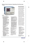
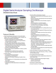
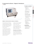
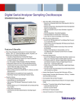
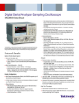
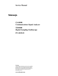
Communications Signal Analyzer
CSA8000B
Features & Benefits
Automatic Communication
Measurements (RZ and NRZ)
–
–
–
–
–
Q-factor
Extinction Ratio
Optical Power
Signal-to-Noise Ratio
Jitter
Wide Bandwidth
(DC to 70+ GHz*1 with
up to 12.5 GHz Trigger)
Automatic ITU/ANSI
Mask Testing
Normal, Infinite, Variable
Persistence and Color
Graded Display Modes
Intuitive User Interface
– Large Color Display (10 in.)
– MS Windows Operating
System
Modular Architecture
Fast Acquisition Rate
Excellent Signal Fidelity (Jitter
<800 fsec RMS – Typical)
Communications Signal Analysis Solutions
Specifically designed for high-performance
communications applications, the CSA8000B
Communications Signal Analyzer is the
ideal tool for design evaluation and manufacturing test of datacom and telecom
components, transceiver subassemblies
and transmission systems.
Modularity and Flexibility
The CSA8000B generates measurement
results, not just raw data, with time and
amplitude histograms, mask testing and
statistical measurements. It provides a
communications-tailored measurement
set that includes jitter, noise, duty cycle,
overshoot, undershoot, extinction ratio,
Q-factor, mean optical power and amplitude measurements for both RZ and
NRZ signals.
The available optical modules provide
complete optical test solutions for both
telecom (155 Mb/s to 43 Gb/s) and datacom (FibreChannel, InfiniBand and Gigabit
Ethernet) applications.
In addition, mask testing of SDH/SONET,
Gigabit Ethernet and other standards
simplifies conformance testing.
A large, full color display helps you to
discriminate waveform details. Colorgrading of waveform data adds a third
dimension, sample density, to your
signal acquisitions and analyses.
1
Optical Signal Analysis • www.tektronix.com/optical
The CSA8000B supports a large and growing family of optical and electrical plug-in
modules. This modular architecture lets
you configure the instrument with the right
features for your application both now and
in the future.
Each optical module includes all of the
elements necessary for communications
testing, including an optical to electrical
converter, an average power monitor, up
to five data rate filters, a full bandwidth
path and a low-noise electrical sampler.
In addition, clock recovery is available as
an option for most optical modules.
The electrical plug-ins include a variety of
modules with bandwidths up to 70+ GHz
and specialized features such as Time
Domain Reflectometry (TDR). High bandwidth
probes are also available for constructing a
total acquisition and measurement solution.
FrameScan™ Acquisition Mode
– Isolate Data
Dependent Faults
– Examine Low-power
PRBS Signals
– Eliminate Random Noise
and Jitter Via Averaging
Windows 2000 for Enhanced
Network Security
Applications
Manufacturing/Testing
for ITU/ANSI Conformance
Designing/Verification
of Telecom and Datacom
Elements
*1 Bandwidth is determined by plug-in modules and
may exceed 70 GHz should higher speed modules
become available in the future.
Communications Signal Analyzer
CSA8000B
2
Optical Signal Analysis • www.tektronix.com/optical
Communications Signal Analyzer
CSA8000B
Superior Performance
With its industry-best horizontal timebase
stability, trigger jitter, signal sensitivity and
noise performance, the CSA8000B ensures
the most accurate acquired signal for
high-speed optical communications testing.
The CSA8000B’s multi-processor architecture, with dedicated per channel digital
signal processors (DSP), also provides
industry-best waveform acquisition rates
that shorten test times.
TM
The CSA8000B’s FrameScan acquisition
mode can be used with a variety of BERTs
and/or protocol analyzers to isolate pattern
dependent effects in transmitters or show
the bit sequence leading up to a mask
violation. FrameScan acquisition mode also
allows averaging of eye diagrams. This can
be used to extract a clean eye diagram
from noisy low-level signals.
8000 Series Sampling
Oscilloscope Platform
The CSA8000B is built on Tektronix’
sampling oscilloscope platform that combines familiar MS Windows-based PC
technologies with world-class waveform
acquisition technology.
This platform provides a wide array of
standard instrumentation and communications interfaces (such as GPIB, Parallel
Printer Port, RS-232-C and USB Serial
Ports and an Ethernet LAN connection).
In addition, the platform includes several
mass storage devices (floppy disk, removable hard drive and CD-ROM). Gated
triggering, a feature that allows the exclusion of selected time periods from being
measured, is offered as an option.
Finally, because the system supports an
Open Windows environment, new levels of
data analysis can be done directly on the
instrument using commercially available
software packages.
Additionally, TekVISATM, a standard software
accessory, allows the instrument to be
placed under the control of software applications (e.g., LabView, LabWindows, Visual
Basic, Microsoft Excel, C, etc.) running on
the instrument, or on external PC workstations network connected to the instrument,
without the need for a GPIB hardware interface. Plug and play drivers for LabView and
other programs are also supplied.
8000 Series Sampling
Oscilloscope Optical
Modules
80C01 Multi-rate Telecom Sampling
Module – The 80C01 module supports
waveform conformance testing of longwavelength (1100 to 1650 nm) signals at
622, 2488 Mb/s and 9.953 Gb/s as well as
general-purpose testing with up to 20 GHz
optical bandwidth. With its clock recovery
option, the 80C01 provides testing solutions
for 622 and 2488 Mb/s telecom applications.
80C02 High-performance Telecom
Sampling Module – The 80C02 module is
optimized for testing of long-wavelength
(1100 to 1650 nm) signals at 9.953 Gb/s
(SONET OC-192/SDH STM-64). With its
high optical bandwidth of 30 GHz (typical), it
is also well-suited for general-purpose highperformance optical component testing. The
80C02 can be optionally configured with
clock recovery that supports 9.953 Gb/s
telecom standards.
80C07B Multi-rate, Datacom & Telecom
Optical Sampling Module – The 80C07B
module is a broad wavelength (700 to 1650
nm) multi-rate optical sampling module
optimized for testing datacom/telecom
signals from 155 to 2500 Mb/s. With its
amplified O/E converter design, this module
provides excellent signal-to-noise performance, allowing users to examine low-power
optical signals. The 80C07B can be optionally
configured with clock recovery that supports
155, 622, 1063, 1250, 2125, 2488, 2500
and 2666 Mb/s rates.
80C08C Multi-rate, Datacom & Telecom
Optical Sampling Module with 10 GbE
Forward Error Correction – The 80C08C
module is a broad wavelength (700 to
1650 nm) multi-rate optical sampling
module providing datacom rate testing
for 10GbE applications at 9.953, 10.3125,
11.0957 Gb/s and 10G FibreChannel
applications at 10.51875 Gb/s. The 80C08C
also provides telecom rate testing at 9.953,
10.664, and 10.709 Gb/s. With its amplified O/E converter design, this module provides excellent signal-to-noise performance
and high optical sensitivity, allowing users
to examine low-power level optical signals.
The 80C08C can be optionally configured
with clock recovery options that can support
any standard or user defined rate in the
continuous range from 9.8 to 12.6 Gb/s.
80C10 65 GHz 40 Gbps Optical Sampling
Module with 43 Gbps ITU-T G.709
Forward Error Correction – The 80C10
module provides integrated and selectable
reference receiver filtering, enabling conformance testing at either 1310 nm or 1550
nm for 39.813 Gbps (OC-768/STM-256)
and 43.018 Gbps (43 Gbps ITU-T G.709
FEC) rates. In addition to the filter rates,
the user may also choose selectable bandwidths of 30 GHz or 65 GHz for optimal
noise vs. bandwidth performance for accurate signal characterization.
80C11 Multi-rate, Datacom & Telecom
Optical Sampling Module – The 80C11
module is a long wavelength (1100 to 1650
nm) multi-rate optical sampling module
optimized for testing 10 Gb/s datacom and
telecom standard rates at 9.953, 10.3125,
Optical Signal Analysis • www.tektronix.com/optical
3
Communications Signal Analyzer
CSA8000B
10.51875, 10.664, 10.709, and 11.0957
Gb/s. With its high optical bandwidth of up
to 30 GHz (typical) it is well-suited for general purpose high-performance 10 Gb/s
optical component testing. The 80C11 can
be optionally configured with clock recovery
options that can support any standard or
user defined rate in the continuous range
from 9.8 to 12.6 Gb/s.
80C12 Multi-rate, Datacom & Telecom
Optical Sampling Module – The 80C012
module is a broad wavelength (700 to 1650
nm) multi-rate optical sampling module providing multi-rate telecom and datacom testing. This highly flexible module can be configured to support either lower data rate
applications (1 to 4 Gb/s) or a wide variety
of 10Gb/s applications. The low data rate
applications include: 1, 2, and 4 Gb/s
FibreChannel and “by 4” wavelength division multiplex standards such as 10GBase-X4
and 4-Lane 10 Gb/s FibreChannel. The supported 10Gb/s application includes both
datacom and telecom application. The supported 10Gb/s datacom applications include
10GbE applications at 9.953, 10.3125,
11.0957 Gb/s and 10G FibreChannel applications at 10.51875 Gb/s. The 80C12 also
provides telecom rate testing at 9.953,
10.664, and 10.709 Gb/s. With its amplified
O/E converter design, this module provides
excellent signal-to-noise performance and
high optical sensitivity, allowing users to
examine low-power level optical signals.
Clock recovery for the 80C12 is provided
via the 80A05 (sold separately).
8000 Series Sampling
Oscilloscope Electrical
Modules
80E01 Sampling Module – The 80E01 is
a single-channel, 50 GHz bandwidth sampling module. The 80E01 has a measured
bandwidth of 50 GHz or more and a calculated rise time of 7.0 ps or less. Displayed
noise is typically 1.8 mVRMS. The front-panel
4
Optical Signal Analysis • www.tektronix.com/optical
connector is female 2.4 mm and an adapter
is provided (2.4 mm male to 2.92 mm
female) to maintain compatibility with SMA
connector systems.
80E02 Low-noise Sampling Module –
The 80E02 is a dual-channel, 12.5 GHz
sampling module specifically designed for
low-noise measurements in digital communications and device characterization applications. It provides an acquisition rise time
of 28 ps and typically 400 µVRMS of displayed noise. The 80E02 is the ideal instrument for low-noise applications. Common
applications for the 80E02 are capturing
and displaying switching characteristics
of high-speed communications circuits,
making accurate statistical measurements
of signal noise and signal timing jitter or
obtaining stable timing measurements of
fast digital ICs.
80E03 Sampling Module – The 80E03 is
a dual-channel, 20 GHz sampling module.
This sampling module provides an acquisition rise time of 17.5 ps.
80E04 TDR Sampling Module – The
80E04 is a dual-channel, 20 GHz sampling
module with TDR capability. This sampling
module provides an acquisition rise time of
17.5 ps, with a typical 20 GHz equivalent
bandwidth. The TDR feature provides high
resolution with true differential capability
and fast 35 ps reflected rise time of the
TDR slope.
80E06 70+ GHz Sampling Module – The
80E06 is a single channel, 70+ GHz (typical
bandwidth) sampling module with 5.0 ps
calculated rise time. Typical RMS noise is
1.8 mV. This sampling module provides a
1.85 mm (Type V) front-panel connector
and a precision adapter to 2.92 mm with a
50 Ω SMA termination. 1 meter or 2 meter
length Extender Cables can be ordered for
remote operation of the sampling module
from the sampling oscilloscope mainframe.
80A05 Electrical Clock Recovery Module –
The 80A05 enables clock recovery for electrical signals, as well as internal triggering
on the recovered clock. The module recovers clocks from serial data streams for all of
the most common electrical standards in
the 50 Mb/s to 4.26 Gb/s range. Option
10G adds support for standard rates up to
12.6 Gb/s. The module accepts either single-ended or differential signals at its input,
providing both single-ended and differential
clock recovery. This module also serves as
the clock recovery module for the 80C12.
Characteristics
Signal Acquisition
Acquisition Modes – Sample (normal), envelope
and average.
Number of Sampling Modules Accommodated –
Up to four, dual-channel electrical and two, singlechannel optical sampling modules.
Number of Simultaneously Acquired Inputs –
Eight channels maximum (eight electrical or two
optical and six electrical).
Vertical Systems
Rise Time/Bandwidth – Determined by the
sampling modules used.
Vertical Resolution – 14 bits over the sampling
modules’ dynamic range.
Horizontal System
Main and Magnification View Timebases – 1ps/div
to 5 ms/div in 1-2-5 sequence or 1 ps increments.
Maximum Trigger Rate – 200 kHz.
Typical Acquisition Rate – 150 Ksamples/sec
per channel.
Time Interval Accuracy –
Horizontal scale: <21 ps/div: 1 ps + 1% of interval.
Horizontal scale: ≥21 ps/div:
8 ps +0.1% of interval (short-term optimized mode).
8 ps + 0.01% of interval (locked to 10 MHz mode).
Horizontal Deskew Range: –500 ps to +100 ns on
any individual channel in 1 ps increments.
Record Length – 20, 50, 100, 250, 500, 1000,
2000 or 4000 samples.
Magnification Views – In addition to the main timebase, the CSA8000B supports two magnification
views. These magnifications are independently
acquired using separate timebase settings which
enable higher resolution sampling.
Communications Signal Analyzer
CSA8000B
Trigger System
Cursors – Dot, vertical bar and horizontal bar cursors.
Trigger Sources –
External direct trigger.
External pre-scaled trigger.
Internal clock trigger: Internally connected
to direct trigger.
Clock recovery triggers (from optical sampling modules) – internally connected to pre-scaled trigger.
Waveform Processing –
Up to eight math waveforms can be defined and
displayed using the following math functions: Add,
Subtract, Multiply, Divide, Average, Differentiate,
Exponentiate, Integrate, Natural Log, Log, Magnitude,
Min, Max, Square Root and Filter.
Trigger Sensitivity –
External direct trigger output:
50 mV, DC –4 GHz (typical).
100 mV, DC –3 GHz (guaranteed).
Pre-scaled trigger input:
800 mV, 2 to 3 GHz (guaranteed).
600 mV, 3 to 10 GHz (guaranteed).
1000 mV, 10 to 12, 5 GHz (typical).
Jitter –
Short-term jitter optimized mode:
≤0.8 psRMS +5 ppm (typical).
≤1.2 psRMS +10 ppm (max.).
Locked to 10 MHz reference:
1.6 psRMS+0.04 ppm of position (typical).
≤2.5 psRMS +0.01 ppm of position (max.).
In addition, measurement values can be utilized as
scalars in math waveform definitions.
Mask Testing –
In addition to user-defined masks, the following
predefined masks are built-in:
Standard
Rate (Gb/s) unless
otherwise noted
STM-0/OC-1
51.84 Mb/s
STM-1/OC-3
155.52 Mb/s
STM-4/OC-12
622.08 Mb/s
STM-16/OC-48
2.4883
STM-64/OC-192
9.9533
STM-256/OC-768
39.81312
FEC 2.666
2.66606
Trigger Level Range – ±1.0 V.
FEC 10.66
10.6642
Trigger Input Range – ±1.5 V.
FEC 10.709
10.709
Trigger Holdoff – Adjustable 5 µs to 100 ms in
2 ns increments.
FEC 43 Gb/s G.709
43.018
External Trigger Gate (optional) – TTL logic 1
enables gate, a TTL logic 0 disables gate, maximum
non-destruct input level ±5 V.
FC-10 G
10.51875
FC-133
132.813 Mb/s
FC-266
265.6 Mb/s
Touch Screen Display – 10.4 in. diagonal, color.
FC-531
531.2 Mb/s
Colors – 16,777,216 (24 bits).
FC-1063
1.0625
Video Resolution – 640 horizontal by 480 vertical
displayed pixels.
FC-2125
2.125
FC-4250
4.250
Math/Measurement System Measurements –
The CSA8000B supports up to eight simultaneous
measurements, updated three times per second
with optional display of per measurement statistics
(min, max, mean and standard deviation).
10 G BASE-X4
3.125
10 G BASE-W
9.95328
10 G BASE-R
10.3125
10 GbE FEC
11.097
Measurement Set –
Automated Measurements include RZ, NRZ, and
Pulse signal types and the following:
Amplitude Measurements: High, Low, Amplitude,
Max, Mid, Min, +Width, Eye Height, Eye Opening
Factor, Pulse Symmetry, Peak-to-Peak, Pk-Pk,
+Overshoot, –Overshoot, Mean, +Duty Cycle, Cycle
Mean, RMS, Cycle RMS, AC RMS, Gain, Extinction
Ratio (Ratio, %, dB), Suppression Ratio (Ratio, %,
dB), Peak to Peak Noise, RMS Noise, Q-Factor, SNR,
Average Optical Power, (dBm, watts), Phase, Optical
Modulation Amplitude.
Timing Measurements: Rise, Fall, Period, Bit Rate,
Bit Time, Frequency, Crossing (%, Level, Time),
+Cross, –Cross, Jitter (pk-pk, RMS), Eye Width,
+Width, –Width, Burst Width, +Duty Cycle, –Duty
Cycle, Duty Cycle Distortion, Delay, Phase.
Area Measurements: Area, Cycle Area.
InfiniBand
2.500
Gigabit Ethernet
1.2500
Internal Clock – Adjustable from 25 to 200 kHz
(drives TDR, internal clock output and calibrator).
Display Features
FEC 42.66
42.656914
Power Requirements
Line Voltage and Frequency –
100 to 240 VAC ±10% 50/60 Hz.
115 VAC ±10% 400 Hz.
Environmental
Temperature –
Operating: +10 ºC to +40 ºC.
Nonoperating: –22 ºC to +60 ºC.
Relative Humidity –
Operating: Floppy disk and CD-ROM not installed:
20% to 80% at or below 40 ºC (upper limit derates
to 45% relative humidity at 40 ºC).
Nonoperating: 5% to 90% at or below 60 ºC (upper
limit de-rates to 20% relative humidity at +60 ºC).
Altitude –
Operating: 3,048 m (10,000 ft.).
Nonoperating: 12,190 m (40,000 ft.).
Electromagnetic Compatibility – 89/336/EEC.
Safety – UL3111-1, CSA1010.1, EN61010-1,
IEC61010-1.
Physical Characteristics
for Optical Sampling
Modules
Dimensions
(mm/inches)
Width Height Depth
80C01 165/6.5 25/1.0 305/12.0
80C02 165/6.5 25/1.0 305/12.0
80C07B 165/6.5 25/1.0 305/12.0
80C08C 165/6.5 25/1.0 305/12.0
80C10 165/6.5 25/1.0 305/12.0
80C11 165/6.5 25/1.0 305/12.0
80C12 165/6.5 25/1.0 305/12.0
Weight
(kg/lb)
Net
<2.61/<5.75
<2.61/<5.75
<1.36/<3.0
<1.22/<2.7
>2.61/>5.75
<1.22/<2.7
<2.61/<5.75
Optical Signal Analysis • www.tektronix.com/optical
5
Communications Signal Analyzer
CSA8000B
Optical Sampling Module Characteristics (Refer to Optical Sampling Module
User Manual for more detailed information)
Application Type
Standard and Supported
Data Filtering Rates
Number of
Input Channels
Effective
Wavelength Range
Calibrated Wavelengths
80C01
Tributary Telecom
OC-12/STM-4 (622 Mb/s),
OC-48/STM-16 (2.488 Gb/s),
OC-192/STM-64 (9.953 Gb/s)
1
1100 nm to 1650 nm
1310 nm and 1550 nm (±20 nm)
80C02
10 Gb/s Telecom
OC-192/STM-64 (9.953 Gb/s)
10GBASE-W (9.953 Gb/s)
1
1100 nm to 1650 nm
1310 nm and 1550 nm (±20 nm)
80C07B
Tributary
Datacom/Telecom
Standard Included:
OC-48/STM-16 (2.488 Gb/s),
InfiniBand, 2 GbE (2.500 Gb/s);
Optional (choose any two):
OC-3/STM-1 (155 Mb/s),
OC-12/STM-4 (622 Mb/s),
FibreChannel (1.063 Gb/s),
GbE (1.250 Gb/s),
2G FibreChannel (2.125 Gb/s)
1
700 nm to 1650 nm
780 nm, 850 nm, 1310 nm,
and 1550 nm (±20 nm)
80C08C
10 Gb/s
Datacom/Telecom
OC-192/STM-64 (9.953 Gb/s),
10GBASE-W (9.953 Gb/s),
10GBASE-R (10.31 Gb/s),
10G FibreChannel (10.52 Gb/s),
ITU-T G.975 FEC (10.664 Gb/s),
ITU-T G.709 (10.709 Gb/s),
10 GbE FEC (11.1 Gb/s)
1
700 nm to 1650 nm
780 nm, 850 nm, 1310 nm,
and 1550 nm (±20 nm)
80C10
40 Gb/s Telecom
OC-768/STM-256 (39.813 Gb/s),
ITU-T G.709 FEC (43.018 Gb/s)
1
1310 nm and 1550 nm
1310 nm and 1550 nm (±20 nm)
80C11
10 Gb/s
Datacom/Telecom
OC-192/STM-64 (9.953 Gb/s),
10GBASE-W (9.953 Gb/s),
10GBASE-R (10.31 Gb/s),
10G FibreChannel (10.52 Gb/s),
ITU-T G.975 FEC (10.664 Gb/s),
ITU-T G.709 (10.709 Gb/s),
10 GbE FEC (11.1 Gb/s)
1
1100 nm and 1650 nm
1310 nm and 1550 nm (±20 nm)
80C12
FibreChannel,
Datacom rates
between 2.5 Gb/s
and 10 Gb/s
Option 10G: 10 Gb/s
multistandard
low cost
Option 10G: OC192/STM64
9.953 Gb/s
10GBase-W 9.953 Gb/s
10GBase-R 10.31 Gb/s
10 GFC 10.51 Gb/s
G.975 FEC 10.66 Gb/s
G.709 FEC 10.71 Gb/s
10 GbE FEC 11.10 Gb/s
Option F1: 1.063 Gb/s,
2.125 Gb/s, and 4.25 Gb/s FC
Option F2: 2.125 Gb/s,
4.25 Gb/s FC, 9 GHz
Option F3: 1.063 Gb/s,
2.125 Gb/s FC, 9 GHz
Option F4: 2.125 Gb/s,
10GBase-LX4, 3.188 Gb/s,
4.25 Gb/s FC
Option F5: 10GBase-LX4,
3.188 Gb/s, 4.25 Gb/s FC, 9 GHz
Option F6: 2.125 Gb/s FC,
10GBase-LX4, 3.188 Gb/s, 9 GHz
Option FC: 11GBase-LX4 filter,
3.188 Gb/s, 3.318 GHz, 9 GHz
1
700 nm to 1650 nm
850, 1310 and
1550 nm (±20 nm)
6
Optical Signal Analysis • www.tektronix.com/optical
Communications Signal Analyzer
CSA8000B
Optical Sampling Module Characteristics (continued)
Clock Recovery
(Optional)
Clock Recovery
Outputs
Unfiltered Optical
Bandwidth*1
Absolute Maximum
Nondestructive
Optical Input
Internal Fiber
Diameter
80C01
Option CR: 622 Mb/s,
2.488 Gb/s
±Clock, ±Data
20 GHz
5 mW average;
10 mW peak power
at wavelength of highest
relative responsivity
9 µm/125 µm single-mode
80C02
Option CR: 9.953 Gb/s
Clock,
Clock/16, Data
28 GHz
5 mW average;
10 mW peak power
at wavelength of highest
relative responsivity
9 µm/125 µm single-mode
80C07B
Option CR1: 155 Mb/s,
622 Mb/s, 1.063 Gb/s,
1.250 Gb/s, 2.125 Gb/s,
2.488 Gb/s, 2.500 Gb/s,
2.666 Gb/s
±Clock, ±Data
2.5 GHz
5 mW average;
10 mW peak power at
wavelength of
highest responsivity
62.5 µm/125 µm multi-mode
80C08C
Option CR1: 9.953 Gb/s,
10.31 Gb/s;
Option CR2: 10.31 Gb/s,
10.52 Gb/s;
Option CR4: Continuous
from 9.8 Gb/s to 12.6 Gb/s
Clock, Clock/16
10 GHz
1 mW average;
10 mW peak power at
wavelength of
highest responsivity
Single-mode and
multi-mode fibers up
to core diameter
of 62.5 µm
80C10
Future Upgradeable
Future
65 GHz
20 mW average;
60 mW peak power at
wavelength of highest
relative responsivity
9 µm/125 µm single-mode
80C11
Option CR1: 9.953 Gb/s;
Option CR2: 9.953 Gb/s,
10.664 Gb/s;
Option CR3: 9.953 Gb/s,
10.709 Gb/s;
Option CR4: Continuous
between 9.8 Gb/s
to 12.6 Gb/s
CR1: Clock, Clock/16, Data;
CR2, CR3, CR4:
Clock, Clock/16
28 GHz
5 mW average;
10 mW peak power at
wavelength of
highest responsivity
9 µm/125 µm single-mode
80C12
Provided by
separately sold 80A05
(50 Mb/s to 12.6 Gb/s)
(Clk/16, 10G Clk)
4 to 10 Gb/s
depending
on option
1 mW average; 10 mW
peak power at wavelength
of highest responsitivity
Single-mode and
multi-mode fibers up
to core diameter
of 62.5 µm
*1 Values shown are warranted unless printed in an italic typeface which represents a typical value.
Optical Signal Analysis • www.tektronix.com/optical
7
Communications Signal Analyzer
CSA8000B
Optical Sampling Module Characteristics (continued)
Optical
Return Loss
Fiber Input
Accepted
RMS Optical Noise
(typical)
RMS Optical Noise
(maximum)
Independent
Channel Deskew
80C01
>30 dB
single-mode
8.0 µW at 622 Mb/s,
2.488 Gb/s, 9.953 Gb/s,
12.5 GHz; 15.0 µW at 20 GHz
12.0 µW at 622 Mb/s,
2.488 Gb/s, 9.953 Gb/s,
12.5 GHz; 25 µW at 20 GHz
Standard
80C02
>30 dB
single-mode
6.0 µW at 9.953 Gb/s,
12.5 GHz; 10.0 µW at
20 GHz; 15.0 µW at 30 GHz
10.0 µW at 9.953 Gb/s,
12.5 GHz mode; 15 µW at
20 GHz; 30 µW at 30 GHz
Standard
80C07B
>14 dB (multi-mode)
>24 dB (single-mode)
single- or multi-mode
0.50 µW at 155 Mb/s,
622 Mb/s, 1063 Mb/s,
1250 Mb/s; 0.70 µW at
2.488/2.500 Gb/s
1.0 µW at 155 Mb/s,
622 Mb/s, 1063 Mb/s,
1250 Mb/s;
1.5 µW at 2.488/2.500 Gb/s
Standard
80C08C
>14 dB (multi-mode)
>24 dB (single-mode)
single- or multi-mode
1.7 µW at all filter rates
3.0 µW at all filter rates
Standard
80C10
>30 dB
single-mode
40 µW at 39.813 Gb/s,
43.018 Gb/s (1550 nm);
75 µW at 39.813 Gb/s,
43.018 Gb/s (1310 nm);
30 µW at 30 GHz mode
(1550 nm); 55 µW at
30 GHz mode (1310 nm);
85 µW at 65 GHz mode
(1550 nm); 150 µW at
65 GHz mode (1310 nm)
60 µW at 39.813 Gb/s,
43.018 Gb/s (1550 nm);
110 µW at 39.813 Gb/s,
43.018 Gb/s (1310 nm);
50 µW at 30 GHz
(1550 nm); 90 µW at
30 GHz (1310 nm);
120 µW at 65 GHz
(1550 nm); 220 µW at
65 GHz (1310 nm)
Standard
80C11
>30 dB
single-mode
5.5 µW at all filter rates;
10.0 µW at 20 GHz
20.0 µW at 30 GHz
8.0 µW at all filter rates;
14.0 µW at 20 GHz
30.0 µW at 30 GHz
Standard
80C12
>14 dB
(62.5 µm multi-mode)
>24 dB
(9 µm single mode)
single- or multi-mode
Offset
Capability
Power
Meter
Power
Meter Range
Power Meter
Accuracy
Mask Test
Optical Sensitivity*2
80C01
Standard
Standard
+4 dBm to –30 dBm
5% of reading
–8 dBm at 622 Mb/s,
2.488 Gb/s, 9.953 Gb/s;
–5.0 dBm at 20 GHz
80C02
Standard
Standard
+4 dBm to –30 dBm
5% of reading
–9 dBm at 9.953 Gb/s;
–7 dBm at 20 GHz;
–4 dBm at 30 GHz
80C07B
Standard
Standard
+4 dBm to –30 dBm
5% of reading
–22 dBm at 155 Mb/s,
622 Mb/s; –20 dBm at
2488/2500 Mb/s
Below 9 Gb/s: 1.7 µW
Below 9 Gb/s: 3 µW
Above 9 Gb/s and 9 GHz: 3.4 µW Above 9 Gb/s and 9 GHz: 6 µW
Standard
80C08C
Standard
Standard
0 dBm to –30 dBm
5% of reading
–15 dBm at all filter rates
80C10
Standard
Standard
+13 dBm to –21 dBm
5% of reading
0 dBm at 39.813 Gb/s,
43.018 Gb/s; 0 dBm at
30 GHz; +3 dBm
at 65 GHz
80C11
Standard
Standard
+4 dBm to –30 dBm
5% of reading
–10 dBm at all filter rates;
–7 dBm at 20 GHz;
–4 dBm at 30 GHz
80C12
Standard
Standard
0 dBm to –30 dBm
5% of reading
Below 9 Gb/s: –15 dBm
Above 9 Gb/s and
9 GHz: –12 dBm
*2 Smallest power level for mask test. Values represent theoretical typical sensitivity of NRZ eyes for competitive comparison purposes. Assumes instrument peak-peak noise consumes most of the mask margin.
8
Optical Signal Analysis • www.tektronix.com/optical
Communications Signal Analyzer
CSA8000B
Physical Characteristics for Electrical Sampling Modules
Dimensions (mm/inches)
Weight (kg/lb)
Width
Height
Depth
Net
80E01
79/3.1
25/1.0
135/5.3
0.4/0.87
80E02
79/3.1
25/1.0
135/5.3
0.4/0.87
80E03
79/3.1
25/1.0
135/5.3
0.4/0.87
80E04
79/3.1
25/1.0
135/5.3
0.4/0.87
80E06
79/3.1
25/1.0
135/5.3
0.4/0.87
Electrical Sampling Module Characteristics
(Refer to Electrical Sampling Module User Manual for more detailed information)
Application Type
Channels
Input Impedance
Channel Input
Connector
Bandwidth*3
80E01
Microwave
General Purpose
1
50 ±0.5 Ω
2.4 mm female Precision
adapter to 2.92 mm included
with 50 Ω SMA termination
50 GHz
80E02
Low-level Signals
2
50 ±0.5 Ω
3.5 mm female
12.5 GHz*4
80E03
Device Characterization
2
50 ±0.5 Ω
3.5 mm female
20 GHz*4
80E04
TDR Impedance Characterization
with single-ended, common,
differential TDR capability
2
50 ±0.5 Ω
3.5 mm female
20 GHz*4
80E06
High-speed Electrical
Device Characterization
1
50 ±0.5 Ω
1.85 mm female Precision
adapter to 2.92 mm included
with 50 Ω SMA termination
70+ GHz
*3 Values shown are warranted unless printed in an italic typeface which represents a non-warranted characteristic value that the instrument will typically perform to.
*4 Rise time is calculated from the formula Rise time = 0.35/Bandwidth; bandwidth is calculated from the formula Bandwidth = 0.35/Rise time.
Electrical Sampling Module Characteristics (continued)
Rise Time
(10% to 90%)
Dynamic Range
Offset Range
Maximum Input
Voltage
Vertical Number
of Digitized Bits
80E01
7 ps*4
1.0 Vp-p
±1.6 V
±2.0 V
14 bits full scale
80E02
≤28 ps
1.0 Vp-p
±1.6 V
±3.0 V
14 bits full scale
80E03
≤17.5 ps
1.0 Vp-p
±1.6 V
±3.0 V
14 bits full scale
80E04
≤17.5 ps
1.0 Vp-p
±1.6 V
±3.0 V
14 bits full scale
80E06
5.0 ps*4
1.0 Vp-p
±1.6 V
±2.0 V
14 bits full scale
*4 Rise time is calculated from the formula Rise time = 0.35/Bandwidth; bandwidth is calculated from the formula Bandwidth = 0.35/Rise time.
Optical Signal Analysis • www.tektronix.com/optical
9
Communications Signal Analyzer
CSA8000B
Electrical Sampling Module Characteristics (continued)
Vertical Sensitivity
DC Vertical Voltage
Range
Accuracy, Single Point,
Within ±2 ºC of Compensated
Temperature
Typical Step Response Aberrations*5
RMS Noise*5
80E01
10 mV to 1.0 V
full scale
± [2 mV + 0.007 (Offset) +
0.02 (Vertical Value – Offset)]
±3% or less over the zone 10 ns to 20 ps before step transition;
+12%, –5% or less for the first 300 ps following step transition;
+5.5%, –3% or less over the zone 300 ps to 3 ns following step
transition; ±1% or less over the zone 3 ns to 100 ns following
step transition; ±0.5% after 100 ns following step transition
1.8 mV ≤2.3 mV
(maximum)
80E02
10 mV to 1.0 V
full scale
± [2 mV + 0.007 (Offset) +
0.02 (Vertical Value – Offset)]
±3% or less over the zone 10 ns to 20 ps before step transition;
+10%, –5% or less for the first 300 ps following step transition;
±3% or less over the zone 300 ps to 5 ns following step transition;
±1% or less over the zone 5 ns to 100 ns following step transition;
±0.5% after 100 ns following step transition
400 µV ≤800 µV
(maximum)
80E03
10 mV to 1.0 V
full scale
± [2 mV + 0.007 (Offset) +
0.02 (Vertical Value – Offset)]
±3% or less over the zone 10 ns to 20 ps before step transition;
+10%, –5% or less for the first 300 ps following step transition;
±3% or less over the zone 300 ps to 5 ns following step transition;
±1% or less over the zone 5 ns to 100 ns following step transition;
±0.5% after 100 ns following step transition
600 µV ≤1.2 mV
(maximum)
80E04
10 mV to 1.0 V
full scale
± [2 mV + 0.007 (Offset) +
0.02 (Vertical Value – Offset)]
±3% or less over the zone 10 ns to 20 ps before step transition;
+10%, –5% or less for the first 300 ps following step transition;
±3% or less over the zone 300 ps to 5 ns following step transition;
±1% or less over the zone 5 ns to 100 ns following step transition;
0.5% after 100 ns following step transition
600 µV ≤1.2 mV
(maximum)
80E06
10 mV to 1.0 V
full scale
± [2 mV + 0.007 (Offset) +
0.02 (Vertical Value – Offset)]
±5% or less for first 300 ps following step transition
1.8 mV ≤2.4 mV
(maximum)
*5 Values shown are warranted unless printed in an italic typeface which represents a non-warranted characteristic value that the instrument will typically perform to.
TDR System (80E04 only)
80E04*6
Channels
Input Impedance
2
50 ±0.5 Ω
Channel Input Connector
3.5 mm
Bandwidth
20 GHz
TDR Step Amplitude
250 mV (polarity of either step may be inverted)
TDR System Reflected Rise Time
≤35 ps each polarity
TDR System Incident Rise Time
28 ps (typical)
TDR Step Maximum Repetition Rate
TDR System Step
Response Aberrations
200 kHz
±3% or less over the zone 10 ns to 20 ps before step transition;
+10%, –5% or less typical for the first 400 ps following step transition;
±3% or less over the zone 400 ps to 5 ns following step transition;
±1% or less after 5 ns following step transition
*6 Values shown are warranted unless printed in an italic typeface which represents a non-warranted characteristic value that the instrument will typically perform to.
10 Optical Signal Analysis • www.tektronix.com/optical
Communications Signal Analyzer
CSA8000B
Ordering Information
CSA8000B
Communications
Signal Analyzer
Includes: User manual, quick reference card,
MS Windows 2000 compatible keyboard,
MS Windows 2000 compatible mouse, touch
screen stylus, online help, programmer online
guide, power cord.
With OpenChoiceTM software, Tektronix provides
enhanced test and measurement analysis with the
capability of full integration of third-party software
on the Open Windows oscilloscopes. By working
with the industry leaders, National Instruments and
The MathWorks, examples of software programs
from these companies are featured on all Tektronix
Open Windows oscilloscopes.
CSA8000B Options
Option C3 – Three years of Calibration Service.
Option D1 – Calibration data report.
Option D3 – Three years of Calibration
data reports.
Option GT – Gated Trigger.
Option R3 – Extended repair warranty to
three years.
Option 1K – Cart.
Option 1R – Rackmount kit (includes: hardware,
tooling and instructions for converting bench
model to rackmount configuration).
International Power
Plug Options
Option A0 – North America power.
Option A1 – Universal EURO power.
Option A2 – United Kingdom power.
Option A3 – Australia power.
Option A4 – 240 V, North America power.
Option A5 – Switzerland power.
Option A99 – No power cord or AC adapter.
Option AC – China power.
Other Accessories
Calibration Step Generator with Power Cords –
Std, US: 067-1338-00.
A1, Europe: 067-1338-01.
A2, UK: 067-1338-02.
A3, Australia: 067-1338-03.
A4, North America: 067-1338-04.
A5, Switzerland: 067-1338-05.
A6, Japan: 067-1338-06.
80A02 – TDS/CSA8000 Series EOS/ESD Protection
Module (1 channel).
Sampling Module Extender Cable
(1 meter) – Order 012-1568-00.
Sampling Module Extender Cable
(2 meter) – Order 012-1569-00.
2X Attenuator (SMA male-to-female) –
Order 015-1001-01.
5X Attenuator (male-to-female) –
Order 015-1002-01.
Adapter (2.4 mm male to 2.92 mm female) –
Order 011-0157-00.
Power Divider – Order 015-1014-00.
Rackmount Kit – Order 016-1791-01.
P8018 – 20 GHz Single-ended TDR Probe.
P7225 – 2.5 GHz Active Probe.
P6209 – 4 GHz Active FET Probe.
P6150 – 9 GHz Passive Probe.
80A01 – Pre-scaled Trigger Amplifier: The 80A01
Pre-scaled Trigger Amplifier provides enhanced
triggering capability on low-level signals up to
12.5 Gb/s. This module plugs into any of the four
available electrical sampling module slots on the
TDS8000B and the CSA8000B mainframes. It is
ideally suited for component designers and manufacturers who are verifying the performance of
optical and electrical components that run at nonstandard clock rates up to 12.5 GHz.
80A03 – TekConnectTM Probe Interface Module.
The 80A03 TekConnect Probe Interface Module
provides an interface to Tektronix P7000 series
high-performance active and differential probes
with 3 GHz bandwidths and higher. The 80A03
accepts up to two P7000 series probes and one
electrical sampling module. It plugs into any of the
four available electrical sampling module slots on
the TDS8000B and CSA8000B mainframes. The
80A03 and P7000 series probes are ideally suited
for probing directly on IC pins, traces, or test points
that are not accessible through a connector.
K4000 – Mobile Workstation.
Optical Signal Analysis • www.tektronix.com/optical
11
Communications Signal Analyzer
Contact Tektronix:
ASEAN / Australasia / Pakistan (65) 6356 3900
CSA8000B
Austria +43 2236 8092 262
Belgium +32 (2) 715 89 70
Brazil & South America 55 (11) 3741-8360
Canada 1 (800) 661-5625
Central Europe & Greece +43 2236 8092 301
Denmark +45 44 850 700
Finland +358 (9) 4783 400
France & North Africa +33 (0) 1 69 86 80 34
Germany +49 (221) 94 77 400
Hong Kong (852) 2585-6688
India (91) 80-2275577
Italy +39 (02) 25086 1
Japan 81 (3) 6714-3010
Mexico, Central America & Caribbean 52 (55) 56666-333
The Netherlands +31 (0) 23 569 5555
Norway +47 22 07 07 00
People’s Republic of China 86 (10) 6235 1230
Poland +48 (0) 22 521 53 40
Republic of Korea 82 (2) 528-5299
Russia, CIS & The Baltics +358 (9) 4783 400
South Africa +27 11 254 8360
Spain +34 (91) 372 6055
Sweden +46 8 477 6503/4
Taiwan 886 (2) 2722-9622
United Kingdom & Eire +44 (0) 1344 392400
USA 1 (800) 426-2200
USA (Export Sales) 1 (503) 627-1916
For other areas contact Tektronix, Inc. at: 1 (503) 627-7111
Updated 23 December 2003
Our most up-to-date product information is available at:
www.tektronix.com
Product(s) are manufactured
in ISO registered facilities.
Copyright © 2004, Tektronix, Inc. All rights reserved. Tektronix products are covered
by U.S. and foreign patents, issued and pending. Information in this publication
supersedes that in all previously published material. Specification and price change
privileges reserved. TEKTRONIX and TEK are registered trademarks of Tektronix,
Inc. All other trade names referenced are the service marks, trademarks or registered trademarks of their respective companies.
01/04
12 Optical Signal Analysis • www.tektronix.com/optical
HB/WWW
85W-13499-9